EP1218061B1 - Dispositif et procede de curietherapie par radiation neutronique - Google Patents
Dispositif et procede de curietherapie par radiation neutronique Download PDFInfo
- Publication number
- EP1218061B1 EP1218061B1 EP00970454A EP00970454A EP1218061B1 EP 1218061 B1 EP1218061 B1 EP 1218061B1 EP 00970454 A EP00970454 A EP 00970454A EP 00970454 A EP00970454 A EP 00970454A EP 1218061 B1 EP1218061 B1 EP 1218061B1
- Authority
- EP
- European Patent Office
- Prior art keywords
- neutron
- capsule
- source
- wire
- guide wire
- Prior art date
- Legal status (The legal status is an assumption and is not a legal conclusion. Google has not performed a legal analysis and makes no representation as to the accuracy of the status listed.)
- Expired - Lifetime
Links
- 238000002725 brachytherapy Methods 0.000 title claims abstract description 36
- 238000000034 method Methods 0.000 title description 13
- 239000002775 capsule Substances 0.000 claims abstract description 115
- 239000000463 material Substances 0.000 claims abstract description 63
- 239000007789 gas Substances 0.000 claims abstract description 33
- 239000001307 helium Substances 0.000 claims abstract description 20
- 229910052734 helium Inorganic materials 0.000 claims abstract description 20
- SWQJXJOGLNCZEY-UHFFFAOYSA-N helium atom Chemical compound [He] SWQJXJOGLNCZEY-UHFFFAOYSA-N 0.000 claims abstract description 19
- 229910052686 Californium Inorganic materials 0.000 claims abstract description 14
- HGLDOAKPQXAFKI-UHFFFAOYSA-N californium atom Chemical compound [Cf] HGLDOAKPQXAFKI-UHFFFAOYSA-N 0.000 claims abstract description 14
- 229910052751 metal Inorganic materials 0.000 claims description 8
- 239000002184 metal Substances 0.000 claims description 8
- 239000008188 pellet Substances 0.000 claims description 5
- 210000001124 body fluid Anatomy 0.000 claims 1
- RVTZCBVAJQQJTK-UHFFFAOYSA-N oxygen(2-);zirconium(4+) Chemical compound [O-2].[O-2].[Zr+4] RVTZCBVAJQQJTK-UHFFFAOYSA-N 0.000 claims 1
- 239000002861 polymer material Substances 0.000 claims 1
- 206010028980 Neoplasm Diseases 0.000 abstract description 88
- 201000011510 cancer Diseases 0.000 abstract description 27
- 210000004027 cell Anatomy 0.000 description 59
- 230000005855 radiation Effects 0.000 description 48
- 238000011282 treatment Methods 0.000 description 45
- 210000004881 tumor cell Anatomy 0.000 description 41
- 238000010586 diagram Methods 0.000 description 27
- 239000002245 particle Substances 0.000 description 18
- 208000003174 Brain Neoplasms Diseases 0.000 description 11
- 208000037265 diseases, disorders, signs and symptoms Diseases 0.000 description 7
- 238000001356 surgical procedure Methods 0.000 description 7
- 210000004556 brain Anatomy 0.000 description 6
- 238000002512 chemotherapy Methods 0.000 description 6
- 201000010099 disease Diseases 0.000 description 6
- 230000000694 effects Effects 0.000 description 6
- KDLHZDBZIXYQEI-UHFFFAOYSA-N Palladium Chemical compound [Pd] KDLHZDBZIXYQEI-UHFFFAOYSA-N 0.000 description 5
- 239000000126 substance Substances 0.000 description 5
- ZOXJGFHDIHLPTG-UHFFFAOYSA-N Boron Chemical compound [B] ZOXJGFHDIHLPTG-UHFFFAOYSA-N 0.000 description 4
- UFHFLCQGNIYNRP-UHFFFAOYSA-N Hydrogen Chemical compound [H][H] UFHFLCQGNIYNRP-UHFFFAOYSA-N 0.000 description 4
- 206010021143 Hypoxia Diseases 0.000 description 4
- 229910052796 boron Inorganic materials 0.000 description 4
- 238000009826 distribution Methods 0.000 description 4
- 239000001257 hydrogen Substances 0.000 description 4
- 229910052739 hydrogen Inorganic materials 0.000 description 4
- 230000001146 hypoxic effect Effects 0.000 description 4
- 230000002285 radioactive effect Effects 0.000 description 4
- 238000001959 radiotherapy Methods 0.000 description 4
- 230000008439 repair process Effects 0.000 description 4
- 238000003466 welding Methods 0.000 description 4
- ZOXJGFHDIHLPTG-BJUDXGSMSA-N Boron-10 Chemical compound [10B] ZOXJGFHDIHLPTG-BJUDXGSMSA-N 0.000 description 3
- QVGXLLKOCUKJST-UHFFFAOYSA-N atomic oxygen Chemical compound [O] QVGXLLKOCUKJST-UHFFFAOYSA-N 0.000 description 3
- 231100000481 chemical toxicant Toxicity 0.000 description 3
- 238000004980 dosimetry Methods 0.000 description 3
- 238000005538 encapsulation Methods 0.000 description 3
- 239000001301 oxygen Substances 0.000 description 3
- 229910052760 oxygen Inorganic materials 0.000 description 3
- 238000002560 therapeutic procedure Methods 0.000 description 3
- 239000003440 toxic substance Substances 0.000 description 3
- 201000010915 Glioblastoma multiforme Diseases 0.000 description 2
- 238000000342 Monte Carlo simulation Methods 0.000 description 2
- 150000001639 boron compounds Chemical class 0.000 description 2
- 230000022534 cell killing Effects 0.000 description 2
- 230000002498 deadly effect Effects 0.000 description 2
- 230000034994 death Effects 0.000 description 2
- 231100000517 death Toxicity 0.000 description 2
- 238000013461 design Methods 0.000 description 2
- 238000011161 development Methods 0.000 description 2
- 230000005670 electromagnetic radiation Effects 0.000 description 2
- 239000012530 fluid Substances 0.000 description 2
- 208000005017 glioblastoma Diseases 0.000 description 2
- 125000004435 hydrogen atom Chemical group [H]* 0.000 description 2
- 238000003780 insertion Methods 0.000 description 2
- 230000037431 insertion Effects 0.000 description 2
- 150000002500 ions Chemical class 0.000 description 2
- 230000002147 killing effect Effects 0.000 description 2
- 238000004519 manufacturing process Methods 0.000 description 2
- 238000009203 neutron therapy Methods 0.000 description 2
- 230000008569 process Effects 0.000 description 2
- 239000012857 radioactive material Substances 0.000 description 2
- 238000001228 spectrum Methods 0.000 description 2
- 238000012360 testing method Methods 0.000 description 2
- 238000012546 transfer Methods 0.000 description 2
- 206010018338 Glioma Diseases 0.000 description 1
- HBBGRARXTFLTSG-UHFFFAOYSA-N Lithium ion Chemical compound [Li+] HBBGRARXTFLTSG-UHFFFAOYSA-N 0.000 description 1
- 101100208721 Mus musculus Usp5 gene Proteins 0.000 description 1
- 206010028813 Nausea Diseases 0.000 description 1
- 229910000566 Platinum-iridium alloy Inorganic materials 0.000 description 1
- 206010057362 Underdose Diseases 0.000 description 1
- 206010047700 Vomiting Diseases 0.000 description 1
- MHTWJRZSIXRPPW-UHFFFAOYSA-H [Cf+3].[Cf+3].[O-]C(=O)C([O-])=O.[O-]C(=O)C([O-])=O.[O-]C(=O)C([O-])=O Chemical compound [Cf+3].[Cf+3].[O-]C(=O)C([O-])=O.[O-]C(=O)C([O-])=O.[O-]C(=O)C([O-])=O MHTWJRZSIXRPPW-UHFFFAOYSA-H 0.000 description 1
- 239000002253 acid Substances 0.000 description 1
- 238000013459 approach Methods 0.000 description 1
- 239000007864 aqueous solution Substances 0.000 description 1
- 230000008901 benefit Effects 0.000 description 1
- 210000004958 brain cell Anatomy 0.000 description 1
- 210000005013 brain tissue Anatomy 0.000 description 1
- 230000030833 cell death Effects 0.000 description 1
- 238000004140 cleaning Methods 0.000 description 1
- 150000001875 compounds Chemical class 0.000 description 1
- 239000000356 contaminant Substances 0.000 description 1
- 230000001419 dependent effect Effects 0.000 description 1
- 238000003745 diagnosis Methods 0.000 description 1
- 208000035475 disorder Diseases 0.000 description 1
- 238000005553 drilling Methods 0.000 description 1
- 230000004907 flux Effects 0.000 description 1
- 210000003128 head Anatomy 0.000 description 1
- -1 helium ion Chemical class 0.000 description 1
- 150000002431 hydrogen Chemical class 0.000 description 1
- 229910001416 lithium ion Inorganic materials 0.000 description 1
- 230000008693 nausea Effects 0.000 description 1
- 230000017074 necrotic cell death Effects 0.000 description 1
- HLXZNVUGXRDIFK-UHFFFAOYSA-N nickel titanium Chemical compound [Ti].[Ti].[Ti].[Ti].[Ti].[Ti].[Ti].[Ti].[Ti].[Ti].[Ti].[Ni].[Ni].[Ni].[Ni].[Ni].[Ni].[Ni].[Ni].[Ni].[Ni].[Ni].[Ni].[Ni].[Ni] HLXZNVUGXRDIFK-UHFFFAOYSA-N 0.000 description 1
- 229910001000 nickel titanium Inorganic materials 0.000 description 1
- 210000004789 organ system Anatomy 0.000 description 1
- 229910052763 palladium Inorganic materials 0.000 description 1
- 230000000737 periodic effect Effects 0.000 description 1
- HWLDNSXPUQTBOD-UHFFFAOYSA-N platinum-iridium alloy Chemical class [Ir].[Pt] HWLDNSXPUQTBOD-UHFFFAOYSA-N 0.000 description 1
- 229920000642 polymer Polymers 0.000 description 1
- 239000002244 precipitate Substances 0.000 description 1
- 210000004761 scalp Anatomy 0.000 description 1
- 239000010935 stainless steel Substances 0.000 description 1
- 229910001220 stainless steel Inorganic materials 0.000 description 1
- 230000004083 survival effect Effects 0.000 description 1
- 229920002994 synthetic fiber Polymers 0.000 description 1
- 238000009121 systemic therapy Methods 0.000 description 1
- 238000011277 treatment modality Methods 0.000 description 1
- 238000012800 visualization Methods 0.000 description 1
- 230000008673 vomiting Effects 0.000 description 1
Images


Classifications
-
- A—HUMAN NECESSITIES
- A61—MEDICAL OR VETERINARY SCIENCE; HYGIENE
- A61N—ELECTROTHERAPY; MAGNETOTHERAPY; RADIATION THERAPY; ULTRASOUND THERAPY
- A61N5/00—Radiation therapy
- A61N5/10—X-ray therapy; Gamma-ray therapy; Particle-irradiation therapy
- A61N5/1001—X-ray therapy; Gamma-ray therapy; Particle-irradiation therapy using radiation sources introduced into or applied onto the body; brachytherapy
- A61N5/1027—Interstitial radiation therapy
-
- G—PHYSICS
- G21—NUCLEAR PHYSICS; NUCLEAR ENGINEERING
- G21G—CONVERSION OF CHEMICAL ELEMENTS; RADIOACTIVE SOURCES
- G21G4/00—Radioactive sources
- G21G4/02—Neutron sources
-
- G—PHYSICS
- G21—NUCLEAR PHYSICS; NUCLEAR ENGINEERING
- G21G—CONVERSION OF CHEMICAL ELEMENTS; RADIOACTIVE SOURCES
- G21G4/00—Radioactive sources
- G21G4/04—Radioactive sources other than neutron sources
- G21G4/06—Radioactive sources other than neutron sources characterised by constructional features
- G21G4/08—Radioactive sources other than neutron sources characterised by constructional features specially adapted for medical application
-
- A—HUMAN NECESSITIES
- A61—MEDICAL OR VETERINARY SCIENCE; HYGIENE
- A61N—ELECTROTHERAPY; MAGNETOTHERAPY; RADIATION THERAPY; ULTRASOUND THERAPY
- A61N5/00—Radiation therapy
- A61N5/10—X-ray therapy; Gamma-ray therapy; Particle-irradiation therapy
- A61N5/1001—X-ray therapy; Gamma-ray therapy; Particle-irradiation therapy using radiation sources introduced into or applied onto the body; brachytherapy
- A61N2005/1019—Sources therefor
- A61N2005/1025—Wires
-
- A—HUMAN NECESSITIES
- A61—MEDICAL OR VETERINARY SCIENCE; HYGIENE
- A61N—ELECTROTHERAPY; MAGNETOTHERAPY; RADIATION THERAPY; ULTRASOUND THERAPY
- A61N5/00—Radiation therapy
- A61N5/10—X-ray therapy; Gamma-ray therapy; Particle-irradiation therapy
- A61N2005/1085—X-ray therapy; Gamma-ray therapy; Particle-irradiation therapy characterised by the type of particles applied to the patient
- A61N2005/109—Neutrons
Definitions
- This invention relates generally to a device for generating particles and electromagnetic radiation that may be used for treating a variety of disorders, such as cancer, tumors and the like and in particular, to a device and method for utilizing neutrons to kill or damage tumor cells within the body of a patient.
- a brain tumor once diagnosed, may typically kill the patient within a very short time frame.
- the five-year survival rate after the diagnosis of glioblastoma multiforme is less than 1%. Therefore, it is desirable to be able to extend the life expectancy of a person with a brain tumor and to improve the quality of life of the patient during the remaining time in his/her life.
- Many different treatments for various cancers, including brain tumors have been developed that attempt to reduce the size of the tumor or eliminate the tumor entirely.
- the treatment of these cancers may be conducted using non-radiation types or treatments.
- chemotherapy may be used in which toxic chemicals are targeted at the cancer or tumor cells (using various well known techniques to target the tumor or cancer cells) so that the cancer or tumor cells are damaged or killed by the toxic chemicals.
- the problem with chemotherapy is that the toxic chemicals also tend to damage other cells or organ systems in the body, and have undesirable side effects, such as nausea, vomiting etc., which lead to a poor quality of life of the patient.
- the treatment typically involves surgery to debulk the tumor (remove as much of the tumor as possible without causing further damage to the healthy cells) followed by some other treatment to combat the cells remaining in the brain after the surgery.
- the treatment after the surgery may include various types of radiation treatment, as described below, which attempt to kill or damage the remaining cancer or tumor cells.
- radiation treatment as described below, which attempt to kill or damage the remaining cancer or tumor cells.
- the problem with this surgery and radiation treatment approach is that some brain tumors are inoperable and the radiation treatment alone does not sufficiently combat the tumor. Due to these limitations, other radiation or particle emitting treatments have been developed.
- various types of radiation and particle emitting devices have been used for treating various diseases and maladies.
- the purpose of these devices is to destroy or disable the undesirable cells, such as tumor cells or cancer cells.
- the particles or electromagnetic energy may strike and break the chemical bonds within the cancer cells so that these cells are destroyed.
- the radiation or particle energy must be highly focused on the tumor or cancer cells because the healthy cells surrounding the tumor or cancer cells are equally susceptible to radiation or particle damage.
- the goal therefore, is to damage the cancer to tumor cells sufficiently with the radiation or particle energy to cause cell death while limiting the exposure of the healthy cells to the damaging particles and radiation.
- typical cells can repair some particle or radiation damage.
- the healthy cells with a more limited exposure than the tumor can repair the damage while the tumor or cancer cells cease functioning or die since they have been exposed to a larger dose of radiation or particles.
- One typical technique for treating cancer or tumor cells is radiation treatment in which electromagnetic radiation is directed towards the tumor or cancer cells in order to damage the tumor or cancer cells.
- the radiation may be x-rays or other types of electromagnetic energy.
- the radiation is typically generated by a source outside the body, passes through the skin and tissue surrounding the tumor or cancer cells and is focused on the tumor or cancer cells so that a majority of the radiation energy is focused on the tumor or cancer cells.
- the problem with radiation treatment is that, to treat tumor or cancer cells inside of the body, the radiation must pass through surrounding healthy tissue which needs to be protected as much as possible from the radiation damage. Therefore, the amount of radiation energy that can be directed at the tumor cells during each treatment is limited by the amount of radiation that the surrounding healthy cells may be exposed to during each treatment.
- the healthy cells will also die which is undesirable.
- the healthy surrounding cells after a radiation treatment, the healthy surrounding cells must be given a chance to repair the damage before any further radiation treatment occurs. Therefore, due to the limited amount of radiation that may be directed to the tumor or cancer cells during each treatment and the period of time between each treatment to permit the healthy cells to repair, radiation treatments are delivered over many weeks. Thus, radiation treatment requires quite some time to damage the tumor or cancer cells sufficiently to kill them and may still cause a fair amount of damage to the surrounding healthy cells since the radiation must pass through the surrounding healthy cells.
- brachytherapy treatment Another typical technique for treating tumor or cancer cells is to use brachytherapy treatment in which a radiation source is inserted into or near the tumor so that the radiation from the radiation source is more focused into the tumor cells with less damage to the surrounding healthy cells.
- the radiation sources may include various elements that emit various types of radiation or particles including beta particles and gamma photons.
- Gamma photons and beta particles are referred to as low linear-energy-transfer (LET) radiation particles in which a particle transfers a small amount of its energy to a tumor cell on each passage.
- LET linear-energy-transfer
- a low LET radiation treatment is naturally ineffective to cancer cells that are hypoxic (have less oxygen than typical healthy cells).
- One type of hypoxic tumor cells are found in brain tumors.
- high LET radiation sources such as neutrons. See R.A. Patchell et al., "A phase I trial of neutron brachytherapy for the treatment of malignant gliomas", The British Journal of Radiology, Vol. 70, pp. 1162 - 1168 (November 1997 ). These neutron sources emit neutrons (a helium nucleus) which interact with the tumor cells to kill or damage them.
- neutrons a helium nucleus
- a high LET radiation particle typically deposits a large fraction of its energy to a cell on each passage, and its cell killing effect is not affected by the amount of oxygen that is in the cells. Therefore, a neutron treatment is equally effective in killing or damaging both normal tumor cells and hypoxic tumor cells.
- the neutron source may be a radioactive element, such as californium (Cf), that may be internally placed near the tumor cells (i.e. the brachytherapy source) or an external neutron beam produced by a nuclear reactor or proton /deuteron accelerator.
- Cf californium
- neutrons typically interact with the tumor cells by colliding with hydrogen nuclei.
- the recoil hydrogen protons i.e. protons
- break chemical bonds of the essential molecules e.g. DNA
- brachytherapy neutron sources The problem with typical brachytherapy neutron sources is that, although they may be inserted into a patient's body, they are too large to be effectively used to treat patients. In particular, the large size of the source prevents the delivery of a desired neutron dose distribution within and around a tumor. The result is either an underdose to the tumor which renders the treatment ineffective, or an overdose to healthy tissues exemplified by the necrosis of the scalp and healthy brain tissues surrounding the tumor as noted in the article cited above.
- Another limitation with brachytherapy neutron sources is that the amount of californium that can be encapsulated in a source seed is too small so that the treatment time required is too long ( ⁇ 30 hours).
- boron neutron capture therapy a compound containing boron-10 is injected into the patient's bloodstream. Due to particular characteristics of the tumor cells, the boron compound is absorbed in greater amounts by the tumor cells than by the healthy cells surrounding the tumor. Then, the part of patient's body that contains the tumor is exposed to an external low-energy (epithermal) neutron beam generated by a nuclear reactor (or an accelerator). The neutrons further slow down and reach thermal equilibrium in tissue. The "thermal" neutrons then interact with the boron-10 in the tumor cells to cause damage.
- a nuclear reactor or an accelerator
- the capture of a thermal neutron by a boron-10 nucleus in a tumor cell instantaneously produces two energetic ions (a lithium ion and a helium ion).
- the two ions break the chemical bonds of the essential molecules (e.g. DNA) and cause damage to the tumor cell.
- the problems of the BNCT are that equal amount of the boron compounds do not enter each tumor cell and that the boron content in tumor cells during a treatment cannot be determined accurately. Therefore, it is impossible to know precisely the neutron fluence necessary to kill the tumor cells.
- an epithermal neutron beam produces a thermal neutron field having its flux peaks at a depth between 2 to 5 cm in tissue. Therefore, it becomes less effective in treating deep seated tumors.
- WO 98/01184 discloses a combination of a capsule for incorporating a radioactive source to be applied in brachytherapy and a guide wire, in which the capsule is attached to the guide wire via an adapter, and the adapter comprises a cable or thread with a flexibility greater than that of the guide wire.
- a neutron brachytherapy device which preferably use californium ( 252 Cf) as the source to deliver neutrons directly to the tumor cells with minimal irradiation or damage to the healthy cells surrounding the tumor.
- a neutron from the source strikes the tumor cells and interact with the hydrogen in the cells to produce a charged hydrogen nucleus known as a recoil proton.
- the recoil proton then breaks chemical bonds of essential molecules (e.g. DNA) in the tumor cells and cause damages or deaths to the cells.
- the neutron source may be used alone or in combination with other treatments including, for example, boron neutron capture therapy (BNCT), surgery and conventional radiation treatments.
- BNCT boron neutron capture therapy
- the neutron source may be used to perform interstitial brachytherapy on tumors such as those occurring in the brain which generally have not responded to systemic therapy treatments.
- the neutron source in accordance with the invention has a higher radioactivity than the previously available neutron sources so that the total treatment time is significantly reduced.
- the neutron source in accordance with the invention also has a smaller size than the previously available neutron sources. The smaller size of the new source allows multiple sources to be more uniformly delivered and distributed within and around a tumor, and therefore provides more desirable dose distributions than the previously available sources.
- the neutron source in accordance with the invention includes a neutron emitting radioactive material, such as Californium ( 252 Cf) in a preferred embodiment, encased within a capsule.
- the capsule in accordance with the invention permits the helium gas generated as the neutron source decays to be dissipated so that the capsule does not need to be periodically processed to release the helium gas.
- the capsule may be welded onto a guide wire to form a source wire so that the source wire and capsule may be inserted into the patient.
- the capsule may be a single or double walled design.
- the neutron emitting material may be loaded into the source wire in various ways as described below.
- the guide wire in accordance with the invention may be braided to strengthen and increase the flexibility of the source wire as well as to prevent the source wire from kinking.
- a catheter with a closed distal end may be inserted into the tumor by a surgeon using various techniques, such as stereotactic visualization and the like, to place the catheter.
- the closed end catheter prevents the patient's fluids from contaminating the source wire.
- the catheters in accordance with the invention may be made of a flexible natural or synthetic material conventionally used in catheter manufacturing that is surrounded by a coiled metal wire. This prevents the catheter and source wire in the catheter from kinking and becoming lodged in the patient and increases the strength of the catheter.
- the metal coiled wire layer may be coiled around the catheter because the metal in the coiled wire does not affect the operation of the neutron source, whereas the operation of typical low LET radiation sources would be significantly affected by the metal coil wrapped around them.
- a neutron source for performing interstitial neutron brachytherapy comprising a neutron emitting source material that is radioactive and decays while releasing helium gas and generating neutrons during the decay.
- the neutron source further comprises a capsule within which the neutron emitting source material is enclosed. The capsule walls do not interfere with the source neutrons and the capsule is sufficiently small so that multiple capsules can be simultaneously inserted into the body of a patient to treat the tumor.
- the neutron source further comprises a guide wire affixed to the capsule wherein the guide wire controlling the positioning of the capsule within the patient.
- the invention is particularly applicable to treating brain tumors and it is in this context that the invention will be described. It will be appreciated, however, that the device in accordance with the invention has greater utility, such as to treating other types of cancers and tumors and for other types of interstitial brachytherapy.
- FIG 1 is a diagram illustrating a patient's head 20.
- the diagram shows the patient's brain 22 with a deep seated tumor 24 that may be treated using the neutron brachytherapy device in accordance with the invention.
- the surgeon may surgically remove a majority of the tumor, known as tumor debulking.
- the neutron brachytherapy device in accordance with the invention may then be used to kill the remaining tumor cells (typically on the periphery of the tumor) instead of a conventional radiation or chemotherapy treatment.
- the neutron brachytherapy device reduces the damage to the surrounding healthy cells so that the amount of killing effect that can be applied to the tumor cells is increased without the undesirable side effects of the conventional radiation or chemotherapy treatments.
- the neutron therapy using the neutron brachytherapy device in accordance with the invention may also be combined with other treatment modalities such as boron neutron capture therapy (BNCT).
- BNCT boron neutron capture therapy
- the tumor due to its size or location in the brain, is inoperable so that the patient is typically left to radiation or chemotherapy treatments. These treatments do not adequately treat the tumor cells since some brain tumors, such as a glioblastoma multiforme, often contain hypoxic cells that do not respond to the conventional radiation or chemotherapy treatments.
- the neutron brachytherapy device in accordance with the invention may be used to shrink the previously inoperable tumor sufficiently so that the tumor may then be removed or de-bulked by the surgeon during a surgical procedure. In this situation, the neutron brachytherapy device may also be used after the debulking procedure to kill the tumor cells remaining after the debulking procedure.
- the neutron brachytherapy device in accordance with the invention generates fast neutrons at energy levels of about 1 -5 MeV of energy.
- the neutrons exiting the neutron brachytherapy source strike hydrogen atoms in the tumor cells, and the resulting charged hydrogen nuclei (i.e. recoil protons) are capable of breaking chemical bonds of essential molecules (e.g. DNA) in the tumor cell and thus damage or kill the tumor cell.
- the neutron brachytherapy device kills the tumor cells via the recoil protons produced by the elastic collisions between the source neutrons and the hydrogen nuclei in tissue.
- FIG. 2 is a diagram illustrating an example of one or more neutron brachytherapy devices 30 in accordance with the invention placed in the tumor 24 to kill or damage the tumor cells.
- the tumor 24 is shown without the surrounding healthy brain cells.
- the number of neutron sources inserted into the tumor in accordance with the invention may be varied.
- each neutron brachytherapy device 30 may include a hollow catheter 32 with a closed end that has been inserted into a predetermined portion of the tumor by the surgeon.
- a source wire 34 may fit within the catheter and is inserted into the catheter by a computer-controlled remote afterloader system.
- the source wire 34 may include a guide wire 36 and a neutron source capsule 38 that may be attached to the end of the guide wire.
- the neutron source capsule may contain the neutron generating material, that may be Cf 252 in a preferred embodiment.
- the neutron generating material may radioactively decay to generate helium gas and the neutrons that indirectly damage the tumor cells.
- the neutron sources may be left in the tumor for about 1- 5 hours to complete the treatment. Once the treatment has been completed, the brachytherapy devices 30 and the catheters may be removed from the tumor and the entry points for the catheters in the patient are sewn up. Now, the source wire and guide wire in accordance with the invention will be described in more detail.
- FIG. 3 is a diagram illustrating an example of the brachytherapy device 30 in accordance with the invention.
- the catheter 32 and the source wire 34 that fits into the catheter are shown.
- the end of the radiation material 38 may be rounded.
- the catheter 32 with the closed end ensures that the source wire never comes into contact with the fluids of the patient so that the source wire may be used for multiple patients without cleaning the source wire.
- a neutron source wire is very difficult to clean since it must be done in a radiation hot cell to prevent neutron exposure.
- the device 30 may include a metallic wire 40 coiled around one layer of the catheter.
- the coiled wire increases the strength of the source wire, permits the source wire and catheter to be bent to get to difficult locations and prevents the source wire and catheter from becoming kinked.
- a kinked catheter or source wire might cause the neutron source 38 to be stuck within the patient so that the patient receives an unwanted dose of neutrons.
- FIG 4 is a diagram illustrating a first embodiment of a neutron source wire 50 in accordance with the invention.
- the neutron source wire may be attached to a guide wire or cable 52 and may include a neutron source 54 attached to the tip of the guide wire or cable 52.
- the guide wire and the neutron source may be surrounded by a coiled wire 56 that acts as a spring increasing the flexibility and strength of the neutron source wire and prevents the neutron source wire from kinking so that the neutron source is less likely to be stuck within the patient.
- the guide wire may be a braided wire as described below with reference to Figures 6A - 6C or may be made of a single nitinol material wire that also may be surrounded by a coiled wire.
- the coiled wire 56 may be securely attached to the guide wire or cable 52 by a weld 58 at an end opposite from the source.
- the coiled wire may be metallic since metal does not affect the effectiveness of the neutrons.
- the source wire, including the neutron source and the guide wire may be approximately four to ten feet long.
- the neutron source 54 may include a rounded ball end 60.
- the neutron source 54 may include a source capsule 64 containing a neutron source material 65.
- the capsule carrier may include a circular hole 66 at its bottom into which the guide wire 52 may be placed. The capsule carrier and the guide wire may then be rigidly attached together, such as by welding in a preferred embodiment.
- the neutron source 54 may further include one or more vent holes 63 to allow the helium gas to escape the capsule and prevent a pressure build-up over time in the capsule.
- a first hole 67 connects the neutron source material 65 to a gas compartment 69 formed near the end of the guide wire 52. The other holes allow the helium gas to escape from the gas compartment 69 to the atmosphere in order to release the pressure.
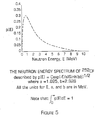
- the neutron source material in accordance with a preferred embodiment of the invention may be an radioactive element from the periodic table known as californium (Cf 252 ).
- Californium has a half-life of about 2.6 years. A majority (97%) of the decay of Californium produces helium gas (alpha particles), but the decay also produces neutrons.
- the neutron energy spectrum of the Californium used in the preferred embodiment is shown in Figure 5 . Notice that the peak of the neutron energies occurs between about 1 MeV and 5 MeV.
- the neutron source material may be formed using various different techniques and certain materials as described in a paper entitled, " Development of High-activity 252Cf Sources for Neutron Brachytherapy” by R.C. Martin et al., Appl. Radiat. Isot., Vol. 48, No. 10 - 12, pp. 1567 -1570 (1997 ).
- a heavily shielded hot cell must be used.
- Palladium (Pd) may be deposited onto a fine precipitate of californium oxalate, Cf 2 (C 2 O 4 ), in an aqueous solution.
- the Pd-coated particles may then be dried, calcined to Pd-coated Cf 2 O 3 , pressed into a pellet at 50% of the desired density, sintered at a predetermined temperature at about 1300 degrees, pressed again to 90% of the desired density and then pressed into a capsule of platinum-iridium alloy.
- the source capsule is 0.5 - 2 mm in outside diameter, that is comparable to other beta and gamma brachytherapy sources and may preferably be 3-6 mm long.
- the preferred nominal intensity of the neutron source in accordance with the invention may be 1.0 X 10 9 neutrons per second.
- the amount of Californium in the source wire may vary between 100 ⁇ g and 1 mg.
- the intensity is 2.3 X 10 9 neutrons per second.
- the neutron source may be 50 times smaller than typical neutron sources and 10 times more radioactivity which permits shorter treatment times.
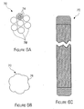
- Figures 6A - 6C are diagrams illustrating the braided guide wire 70 in accordance with the invention.
- the braided guide wire may include a bundle of 7 bundles of wires 72 and each bundle of wire 72 may also be braided with seven single wires 74.
- the braided guide wire may be formed with a 7X7 bundle of braided wires to increase the strength and flexibility of the guide wire.
- the problem with the 7X7 bundle is that an outer surface 76 of the bundle is uneven due to the bundle of braided wires. The problem is that the uneven surface may perforate the catheter into which it is inserted or make is difficult to push the guide wire through the catheter.
- the tips of the various wires may be fused together and rounded and then the tips of the guide wire may be ground down so that the resultant surface of the guide wire is smooth.
- the guide wire may have the flexibility and strength associated with a braided wire, but the smoothness normally associated with a single wire.
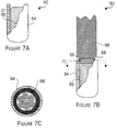
- FIGS 7A - 7C are diagrams illustrating a second embodiment of the neutron source 50 in accordance with the invention.
- a neutron capsule 80 may be formed by placing a neutron emitting material 82, such as californium in a preferred embodiment, into a capsule casing 84. Since the neutron emitting material is exposed during the neutron source production in this embodiment, the neutron source must be produced in a heavily shielded hot cell.
- a smooth braided guide wire (swaged with finished ends as above) 86 may be inserted into the opening in the capsule casing and a weld 88 may be formed around the top of the capsule casing and the guide wire to secure the guide wire to the capsule and seal the neutron emitting material into the capsule.
- An end view of the weld is shown in Figure 7C . Vent holes may also be added in this design.
- FIGs 8A, 8B and 8C illustrate an embodiment of a neutron source wire 90 in which a capsule 91 does not need to be welded onto a guide wire 92.
- the advantage is that there is no possibility of a weld fatiguing and breaking so that the reliability and safety of the neutron source wire 90 is increased.
- an end 93 of the guide wire 92 that fits into the capsule 91 may be fused and ground as described above and may be threaded so that it may be threaded into the capsule as described below.
- the guide wire may also have a tapered section 94 so that there is space between a neutron source 95 and the guide wire into which helium gas may build up when the neutron source wire is assembled as shown in Figure 8B .
- the capsule 91 may include the neutron source 95 which is loaded into the open end of the capsule and a threaded plug 96 (it may also be a slotted headless threaded screw).
- the walls of the capsule may include a threaded section 97.
- the threaded section 97 begins above the top of the neutron source 95 so that the neutron source can not be contacted by the plug 96 and possibly damaged.
- the threaded plug 96 may be aligned with the threads 97 in the capsule walls and screwed into the capsule until the plug fits snugly above the neutron source.
- the slotted portion of the plug may be used to screw the plug down towards the neutron source.
- the plug 96 may include one or more vent holes 98 that permit any helium gas generated by the neutron source to escape into a gas compartment 99 formed between the tapered end 94 of the guide wire and the plug 96.
- the walls of the capsule 91 may further include one or more vent holes 100 adjacent to the gas compartment so that any gas in the gas compartment may pass through the vent holes 100 into the atmosphere.
- the capsule 91 may further include one or more relief flats 101 (as shown in more detail in Figure 8B ) that permit the capsule 91 to be held while the plug 96 and the guide wire 92 are screwed into the capsule.
- the assembled neutron source wire 90 is shown in Figure 9B .
- the relief flats 101 may coincide with the vent holes 100 in the capsule to allow the helium gas to escape the capsule and vent to the outside.
- the entire source wire 90 may also be placed inside an outer coiled wire to provide an additional safety factor as described above. Now, an embodiment for loading a neutron source will be described.
- FIG. 9A is a diagram illustrating an embodiment for loading a neutron source 110 in accordance with the invention.
- the next several diagrams illustrate different techniques for encapsulating the neutron emitting material in a capsule in accordance with the invention.
- the neutron emitting material 112 is formed into a pellet and a hole is formed in the end of a guide wire 114 so that the neutron emitting material may be placed into the end of the guide wire.
- a weld 116 may be formed, using a typical welding system such as a laser welding system, around the neutron emitting material 112 on top of the tip of the guide wire.
- the guide wire would be processed in the same fashion as mentioned above.
- FIG 10 is a diagram illustrating another embodiment for loading a neutron source 120 in accordance with the invention wherein the source 120 may be formed in the heavily shielded hot cell and then may be removed from the hot cell to secure it to the guide wire.
- a bullet shaped capsule casing 122 is formed from a suitable material, such as stainless steel, and a neutron emitting source material 124 may be loaded in the bottom of the capsule casing.
- a plug or seal 126 may be placed in or over the open end in the hot cell which seals the neutron emitting material inside the capsule.
- the seal 126 may be made out of a metal. Once the seal is installed, the entire neutron source 120 may be washed with acid to remove contaminants and any residual neutron emitting material.
- the neutron source 120 may be removed from the hot cell and a guide wire (not shown) may be attached to the neutron source outside of the hot cell which makes the attachment of the guide wire to the neutron source easier.
- FIG 11 is a diagram illustrating a coiled wire assembly 160 in accordance with the invention.
- the outside diameter of the assembly is the same as the neutron source wire. It is significantly shorter in length (approximately 12-15 inches).
- the coiled assembly 160 may be inserted into a catheter before the catheter is inserted into the brain through a burr hole to maintain the rigidity of the catheter during its insertion.
- the coiled wire assembly may include a core 162 that may be wrapped by a coiled spring wire 164 to increase the flexibility and strength of the assembly. The coiled wire assembly is also less likely to be kinked.
- the coiled wire assembly 160 may also include a ball end tip 166 that prevents the coiled wire assembly from puncturing the tip of the closed end catheter during the insertion of the coiled wire assembly into the catheter.
- the coiled wire assembly may also include a handle portion 168 attached to the end of the coiled wire assembly opposite of the ball end tip so that the coiled wire assembly may be manipulated by a surgeon. Since this assembly is almost the same as the neutron source wire, it almost guarantees the source wire can be placed when using the remote controlled delivery system. Now, a single encapsulated neutron source in accordance with the invention will be described.
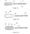
- FIG 12 is a diagram illustrating a single encapsulated source 170 in accordance with the invention.
- a capsule 172 is formed as described above with a neutron emitting source material 174, such as Californium, inside of the capsule.
- the capsule body is formed with an open end, the open end is pointed upwards, the neutron emitting material is loaded into the capsule through the open end, the open end is reshaped to contain the neutron emitting material in the capsule, the capsule is crimped over a wire 176.
- the capsule may then be welded onto the end of a braided guide wire 176 to form the neutron source wire.
- the single encapsulation requires only a single weld at the guide wire connection.
- the single encapsulation neutron source may preferably have an outside diameter of the cylindrical capsule of between 1.2 - 1.8 mm (and more preferably about 1.5 mm), an inner diameter of the capsule of between 1-1.3 mm (and more preferably about 1.1 mm) and a capsule wall thickness of between .005" - .009" (and more preferably about .008").
- FIG 13 is a diagram illustrating another embodiment of the single encapsulated neutron source 180 in accordance with the invention.
- the neutron source may include a capsule (shell) 182 and a plug or cap piece 184 that may fit into the end of the capsule.
- the neutron source material may be placed into the capsule.
- the plug piece 184 may be mechanically fitted into the body piece to seal the neutron emitting material in the capsule.
- the capsule and plug piece may both also have corresponding screw threads so that the plug piece may be screwed into the body piece.
- the capsule and the plug piece are welded together to ensure a tight seal.
- a braided guide wire 186 may be welded into the plug piece to secure the neutron source capsule to the guide wire.
- the dimensions of this embodiment are approximately the same as the embodiment described above with reference to Figure 12 . Now, a double encapsulated neutron source in accordance with the invention will be described.
- FIG 14 is a diagram illustrating a double encapsulated neutron source 190 in accordance with the invention.
- the double encapsulated embodiment may include a neutron emitting source material 192 loaded into an inner capsule 194 and the inner capsule is sealed.
- the walls of the inner capsule may be permeable (e.g., made of a sputtered metal layer that is a few angstroms thick or made of a polymer) so that the helium gas generated by the neutron emitting source material may pass through the walls of the inner capsule to prevent unwanted gas build-up.
- the sealed inner capsule may then be placed within an outer capsule 196 and then the outer capsule may also be sealed.
- the outer capsule may also have permeable walls (as described above) so that the helium gas may also pass through the outer capsule and travel through the catheter to the outside world. Instead of using permeable walls for the capsules, each capsule may have vent holes which permit the gas to escape from within the capsule(s).
- the outer capsule may then be crimped onto a braided guide wire 198 and the guide wire may be welded to the outer capsule.
- the inner capsule may have an outer diameter of between 1-1.3 mm (and preferably about 1.15 mm), an inner diameter of between 0.6 - 1 mm (and preferably about 0.85 mm) and a wall thickness of between .005" - .008" (and preferably about .006").
- the outer capsule may preferably have an outer diameter of between 1.2 - 1.8 mm (and preferably about 1.5 mm), an inner diameter of 1 - 1.4 mm (and preferably about 1.25 mm)and a wall thickness of between .004" - .007" (and preferably about .005").
- the neutron emitting source material may be sealed within two separate capsules to increase the safety of the neutron source.
Claims (23)
- Source de neutrons pour mettre en oeuvre une curiethérapie par rayonnements neutroniques, la source de neutrons comprenant:un matériau source émettant des neutrons (65, 82, 95, 112, 124, 174), le matériau source émettant des neutrons subissant une désintégration radioactive et libérant de l'hélium gazeux et des neutrons pendant la désintégration, le matériau source émettant des neutrons ayant une intensité d'environ 2,3 x 10⁸ neutrons par seconde à environ 2,3 x 10⁹ neutrons par seconde ; etune capsule (38, 64, 80, 91, 172, 182) dans laquelle est encapsulé le matériau source émettant des neutrons, les parois de la capsule n'interférant pas avec les neutrons ; etla capsule de source de neutrons ayant un diamètre externe compris entre 0,5 et 2mm;etla capsule ayant des parois comprenant un matériau qui est perméable à l'hélium gazeux afin que l'hélium gazeux produit par le matériau source émettant des neutrons s'échappe à travers les parois perméables de la capsule de telle sorte que l'hélium gazeux ne s'accumule pas dans la capsule.
- Source de neutrons de la revendication 1, comprenant en outre un fil-guide (36, 52, 92, 114) attaché à la capsule, le fil-guide contrôlant la position de la capsule à l'intérieur du patient.
- Source de neutrons de la revendication 2, dans laquelle le fil-guide comprend un faisceau de fils tressés (70, 86, 176, 186) qui sont flexibles et réduisent le vrillage du fil guide.
- Source de neutrons de la revendication 3, dans laquelle le faisceau de fils-guides comprend en outre un fil tressé central entouré de six fils tressés, dans lequel une pointe du faisceau de fils est arrondie et une surface externe des fils du faisceau est lissée pour former un fil lisse ayant les caractéristiques d'un faisceau de fils.
- Source de neutrons de la revendication 1, comprenant en outre un fil (40, 56, 164) enroulé en hélice autour de la capsule et du fil-guide pour augmenter la résistance et la flexibilité du fil-guide, empêcher le vrillage du fil-guide et assurer la sécurité, en ce que le fil enroulé en hélice piège la capsule si celle-ci se sépare du fil-guide par rupture, le fil enroulé en hélice n'affectant pas l'émission des neutrons.
- Source de neutrons de la revendication 1, dans lequel la capsule comprend un boîtier métallique comportant une extrémité ouverte dans laquelle le matériau source émettant des neutrons est chargé, l'extrémité ouverte du boîtier métallique étant fermée pour sceller le matériau source émettant des neutrons dans le boîtier métallique et le fil-guide étant fixé de façon permanente sur le boîtier métallique.
- Source de neutrons de la revendication 6, dans laquelle la capsule comprend en outre un trou d'évent (63) dans une partie du boîtier métallique pour permettre à l'hélium gazeux produit par la désintégration du matériau source émettant des neutrons de s'échapper de la capsule afin qu'une pression gazeuse ne s'accumule pas dans la capsule.
- Source de neutrons de la revendication 1, dans laquelle la capsule comprend une partie de corps et une partie de bouchon, la partie de corps comprenant une extrémité ouverte dans laquelle est chargé le matériau source émettant des neutrons, la partie de corps et la partie de bouchon s'ajustant mécaniquement l'une à l'autre pour sceller le matériau source émettant des neutrons dans la partie de corps.
- Source de neutrons de la revendication 1, dans laquelle la capsule comprend une partie de corps et une partie de bouchon, la partie de corps comprenant une extrémité ouverte dans laquelle est chargé le matériau source émettant des neutrons, la partie de corps et la partie de bouchon comportant des filets de telle sorte que la partie de corps et la partie de bouchon soient vissées ensemble pour sceller le matériau source émettant des neutrons dans la partie de corps.
- Source de neutrons de la revendication 9, dans laquelle la capsule comprend en outre une capsule interne (194) dans laquelle le matériau source émettant des neutrons (192) est scellé et une capsule externe (196) dans laquelle la capsule interne est scellée.
- Source de neutrons de la revendication 1, dans laquelle le fil-guide comprend un fil de nitinol.
- Source de neutrons de la revendication 1, comprenant en outre un cathéter à extrémité fermée dans lequel est placée la source de neutrons afin de traiter un patient, le cathéter à extrémité fermée empêchant la source de neutrons d'entrer en contact avec les fluides corporels du patient.
- Source de neutrons de la revendication 12, dans laquelle le cathéter à extrémité fermée comprend en outre un fil enroulé en hélice autour du cathéter, le fil enroulé en hélice n'affectant pas l'émission des neutrons.
- Source de neutrons de la revendication 1, dans laquelle la capsule comprend en outre un module de source comprenant un fil ayant un trou central dans lequel une pastille de matériau source émettant des neutrons est placée, et une soudure entourant la pastille et fixant la pastille sur le fil.
- Source de neutrons de la revendication 1, dans laquelle la capsule comprend en outre un module de source comprenant un boîtier comportant une extrémité ouverte dans laquelle le matériau source émettant des neutrons est chargé, et un joint formé sur le matériau source émettant des neutrons pour sceller le matériau source émettant des neutrons dans le boîtier.
- Source de neutrons de la revendication 1, dans laquelle la capsule comprend en outre un module de source comprenant un boîtier de source comportant une première cavité et une deuxième cavité opposée à la première cavité pour former une structure en forme de H, le matériau source émettant des neutrons étant chargé dans la première cavité, une soudure étant formée sur la première cavité pour sceller le matériau source émettant des neutrons dans la première cavité, le fil-guide étant inséré dans la deuxième cavité.
- Source de neutrons de la revendication 1, dans laquelle le matériau source émettant des neutrons comprend une quantité prédéterminée de californium, la quantité prédéterminée étant comprise entre environ 100 µg et 1 mg.
- Source de neutrons de la revendication 1, dans laquelle la capsule comprend en outre un boîtier comportant une partie interne filetée (97) dans laquelle est chargé la matériau source émettant des neutrons (95), un bouchon fileté (96) qui se visse dans la partie interne filetée du boîtier et un fil-guide ayant une extrémité filetée qui se visse dans le boîtier au-dessus du bouchon pour former un fil de source de neutrons sans soudures.
- Source de neutrons de la revendication 18, dans laquelle le bouchon comprend en outre un ou plusieurs trous d'évent (98) qui permettent au gaz dégagé par le matériau source émettant des neutrons de s'échapper dans un compartiment de gaz, le boîtier comprenant en outre un ou plusieurs trous d'évent à travers les parois du boîtier qui permettent au gaz contenu dans le compartiment de gaz de s'échapper de la capsule.
- Source de neutrons de la revendication 19, dans laquelle le boîtier comprend en outre un ou plusieurs méplats en relief (101) situés sur les parois extérieures du boîtier pour tenir le boîtier lorsque le bouchon et le fil-guide sont vissés dans les filets du boîtier.
- Source de neutrons de la revendication 1, dans laquelle les parois de la capsule comprennent en outre un ou plusieurs trous d'évent (63) dans les parois de la capsule pour permettre au gaz de s'échapper de l'intérieur de la capsule.
- Source de neutrons de la revendication 1, dans laquelle le matériau des parois comprend une couche de métal pulvérisée qui est suffisamment mince pour permettre au gaz de pénétrer à travers les parois.
- Source de neutrons de la revendication 1, dans laquelle le matériau des parois comprend un matériau polymère.
Applications Claiming Priority (3)
| Application Number | Priority Date | Filing Date | Title |
|---|---|---|---|
| US09/395,324 US6352500B1 (en) | 1999-09-13 | 1999-09-13 | Neutron brachytherapy device and method |
| US395324 | 1999-09-13 | ||
| PCT/US2000/025132 WO2001019450A2 (fr) | 1999-09-13 | 2000-09-13 | Dispositif et procede de curietherapie par radiation neutronique |
Publications (3)
| Publication Number | Publication Date |
|---|---|
| EP1218061A2 EP1218061A2 (fr) | 2002-07-03 |
| EP1218061A4 EP1218061A4 (fr) | 2008-05-28 |
| EP1218061B1 true EP1218061B1 (fr) | 2012-05-02 |
Family
ID=23562556
Family Applications (1)
| Application Number | Title | Priority Date | Filing Date |
|---|---|---|---|
| EP00970454A Expired - Lifetime EP1218061B1 (fr) | 1999-09-13 | 2000-09-13 | Dispositif et procede de curietherapie par radiation neutronique |
Country Status (9)
| Country | Link |
|---|---|
| US (2) | US6352500B1 (fr) |
| EP (1) | EP1218061B1 (fr) |
| JP (1) | JP4574925B2 (fr) |
| AT (1) | ATE555826T1 (fr) |
| AU (1) | AU778456B2 (fr) |
| CA (1) | CA2381996A1 (fr) |
| IL (2) | IL148634A0 (fr) |
| NZ (1) | NZ518274A (fr) |
| WO (1) | WO2001019450A2 (fr) |
Families Citing this family (19)
| Publication number | Priority date | Publication date | Assignee | Title |
|---|---|---|---|---|
| US6551232B1 (en) * | 1999-08-19 | 2003-04-22 | New England Medical Center | Dosimetry for californium-252(252Cf) neutron-emitting brachytherapy sources and encapsulation, storage, and clinical delivery thereof |
| US6352500B1 (en) * | 1999-09-13 | 2002-03-05 | Isotron, Inc. | Neutron brachytherapy device and method |
| US6786858B2 (en) * | 2001-11-02 | 2004-09-07 | Ideamatrix, Inc. | Delivery system and method for interstitial radiotherapy using hollow seeds |
| US7342988B2 (en) * | 2002-02-06 | 2008-03-11 | The Regents Of The University Of California | Neutron tubes |
| EP2008690B1 (fr) | 2002-09-10 | 2013-11-06 | Cianna Medical, Inc. | Appareil de curiethérapie |
| US7093476B2 (en) * | 2004-09-15 | 2006-08-22 | Ut-Battelle, Llc | Method for fabricating thin californium-containing radioactive source wires |
| US7077800B2 (en) * | 2004-09-15 | 2006-07-18 | Ut Battelle, Llc | Cable attachment for a radioactive brachytherapy source capsule |
| US20080004482A1 (en) * | 2006-06-30 | 2008-01-03 | Eddie Michael Zanrosso | Radiation source device |
| NL1032714C2 (nl) * | 2006-10-20 | 2008-04-22 | Isodose Control Intellectual P | Transportkabel en broncapsule met veilige verbindingsconstructie voor het inwendig bestralen van patienten. |
| US8663210B2 (en) * | 2009-05-13 | 2014-03-04 | Novian Health, Inc. | Methods and apparatus for performing interstitial laser therapy and interstitial brachytherapy |
| EP2942343B1 (fr) † | 2009-12-22 | 2019-09-04 | Dow Technology Investments LLC | Réglage du rapport aldéhyde normal:aldéhyde iso dans un procédé d'hydroformylation à ligand mixte |
| US20110264220A1 (en) * | 2010-04-23 | 2011-10-27 | Warsaw Orthopedic, Inc. | Device and method for delivering radiation |
| US20120004493A1 (en) * | 2010-07-02 | 2012-01-05 | Hedger Troy S | System for delivering treatment agents |
| JP6033853B2 (ja) * | 2011-06-01 | 2016-11-30 | ヌクレトロン オペレーションズ ベー.フェー. | 密封小線源治療用線源アセンブリ |
| US20130123912A1 (en) * | 2011-11-15 | 2013-05-16 | Boston Scientific Scimed, Inc. | Medical device with nosecone and nosecone tube extension |
| US9821174B1 (en) | 2015-02-06 | 2017-11-21 | Gammatile Llc | Radioactive implant planning system and placement guide system |
| US10888710B1 (en) | 2016-11-29 | 2021-01-12 | Gt Medical Technologies, Inc. | Transparent loading apparatus |
| US10580543B2 (en) * | 2018-05-01 | 2020-03-03 | Qsa Global, Inc. | Neutron sealed source |
| TWI757716B (zh) | 2019-04-15 | 2022-03-11 | 禾榮科技股份有限公司 | 微創型中子束產生裝置及微創型中子捕獲治療系統 |
Family Cites Families (55)
| Publication number | Priority date | Publication date | Assignee | Title |
|---|---|---|---|---|
| FR2348714A1 (fr) | 1976-04-20 | 1977-11-18 | Cgr Mev | Appareil de curietherapie |
| US4112306A (en) | 1976-12-06 | 1978-09-05 | Varian Associates, Inc. | Neutron irradiation therapy machine |
| JPS5373892A (en) | 1976-12-11 | 1978-06-30 | Kenkichi Tsukamoto | Improved needle and attached ampule |
| US4197170A (en) | 1977-10-11 | 1980-04-08 | Monsanto Research Corporation | Radiation sources and process |
| US4510924A (en) | 1980-07-10 | 1985-04-16 | Yale-New Haven Hospital, Inc. | Brachytherapy devices and methods employing americium-241 |
| DE3442762A1 (de) | 1984-11-23 | 1986-06-26 | Anwer Dipl.-Ing. 8520 Erlangen Puthawala | Ferngesteuerte afterloading vorrichtung zur brachycurie-therapie von tumoren |
| US5322499A (en) | 1985-09-20 | 1994-06-21 | Liprie Sam F | Continuous sheated low dose radioactive core adapted for cutting into short sealed segments |
| US5141487A (en) | 1985-09-20 | 1992-08-25 | Liprie Sam F | Attachment of radioactive source and guidewire in a branchy therapy source wire |
| DE3534760C1 (de) | 1985-09-28 | 1987-05-07 | Bbc Reaktor Gmbh | Einrichtung zum Erzeugen thermischer Neutronen |
| DE3534686C1 (de) | 1985-09-28 | 1987-05-07 | Bbc Reaktor Gmbh | Einrichtung zum Durchstrahlen eines Objektes mit einer transportablen,thermische Neutronen erzeugenden Quelle |
| US4763642A (en) | 1986-04-07 | 1988-08-16 | Horowitz Bruce S | Intracavitational brachytherapy |
| US4819618A (en) | 1986-08-18 | 1989-04-11 | Liprie Sam F | Iridium/platinum implant, method of encapsulation, and method of implantation |
| USH669H (en) | 1986-12-08 | 1989-09-05 | The United States Of America As Represented By The United States Department Of Energy | Samarium-145 and its use as a radiation source |
| FR2609898B1 (fr) | 1987-01-28 | 1989-03-31 | Commissariat Energie Atomique | Dispositif d'entrainement et de positionnement d'un porte-sources dans un applicateur utilise en curietherapie |
| US4891165A (en) | 1988-07-28 | 1990-01-02 | Best Industries, Inc. | Device and method for encapsulating radioactive materials |
| US4994013A (en) | 1988-07-28 | 1991-02-19 | Best Industries, Inc. | Pellet for a radioactive seed |
| US5084002A (en) | 1988-08-04 | 1992-01-28 | Omnitron International, Inc. | Ultra-thin high dose iridium source for remote afterloader |
| US5183455A (en) | 1988-10-07 | 1993-02-02 | Omnitron International, Inc. | Apparatus for in situ radiotherapy |
| US5480382A (en) * | 1989-01-09 | 1996-01-02 | Pilot Cardiovascular Systems, Inc. | Steerable medical device |
| US4957476A (en) | 1989-01-09 | 1990-09-18 | University Of Pittsburgh | Afterloading radioactive spiral implanter |
| US4963128A (en) | 1989-03-21 | 1990-10-16 | University Of Virginia Alumni Patents Foundation | Chest tube and catheter grid for intrathoracic afterload radiotherapy |
| US5199939B1 (en) | 1990-02-23 | 1998-08-18 | Michael D Dake | Radioactive catheter |
| US5267960A (en) | 1990-03-19 | 1993-12-07 | Omnitron International Inc. | Tissue engaging catheter for a radioactive source wire |
| US5342283A (en) | 1990-08-13 | 1994-08-30 | Good Roger R | Endocurietherapy |
| US5092834A (en) | 1990-10-12 | 1992-03-03 | Omnitron International, Inc. | Apparatus and method for the remote handling of highly radioactive sources in the treatment of cancer |
| US5282781A (en) | 1990-10-25 | 1994-02-01 | Omnitron International Inc. | Source wire for localized radiation treatment of tumors |
| WO1992010932A1 (fr) | 1990-12-17 | 1992-07-09 | Microwave Medical Systems, Inc. | Sonde therapeutique servant a emettre des micro-ondes et des rayonnements nucleaires |
| US5531662A (en) | 1990-12-17 | 1996-07-02 | Microwave Medical Systems, Inc. | Dual mode microwave/ionizing probe |
| US5395300A (en) | 1991-06-07 | 1995-03-07 | Omnitron International, Inc. | High dosage radioactive source |
| AU2861692A (en) | 1991-10-18 | 1993-05-21 | Beth Israel Hospital Association, The | Vascular permeability factor targeted compounds |
| US5317616A (en) | 1992-03-19 | 1994-05-31 | Wisconsin Alumni Research Foundation | Method and apparatus for radiation therapy |
| US5643171A (en) | 1993-05-04 | 1997-07-01 | Neocardia, Llc | Method and apparatus for uniform radiation treatment of vascular lumens |
| US5498227A (en) | 1993-09-15 | 1996-03-12 | Mawad; Michel E. | Retrievable, shielded radiotherapy implant |
| US5599796A (en) | 1993-12-02 | 1997-02-04 | Emory University | Treatment of urogenital cancer with boron neutron capture therapy |
| US5618266A (en) | 1994-03-31 | 1997-04-08 | Liprie; Samuel F. | Catheter for maneuvering radioactive source wire to site of treatment |
| US5503614A (en) | 1994-06-08 | 1996-04-02 | Liprie; Samuel F. | Flexible source wire for radiation treatment of diseases |
| US5857956A (en) | 1994-06-08 | 1999-01-12 | United States Surgical Corporation | Flexible source wire for localized internal irradiation of tissue |
| US5562594A (en) | 1994-06-10 | 1996-10-08 | Duke University | Shielded mini-applicator system for radioactive source treatment of cancer of the uterine cervix |
| JPH10503105A (ja) | 1994-07-22 | 1998-03-24 | ユニバーシティ オブ ワシントン | 定位固定移植方法 |
| US5626829A (en) | 1994-11-16 | 1997-05-06 | Pgk, Enterprises, Inc. | Method and apparatus for interstitial radiation of the prostate gland |
| US5616114A (en) | 1994-12-08 | 1997-04-01 | Neocardia, Llc. | Intravascular radiotherapy employing a liquid-suspended source |
| US5653683A (en) | 1995-02-28 | 1997-08-05 | D'andrea; Mark A. | Intracavitary catheter for use in therapeutic radiation procedures |
| US5851172A (en) | 1995-05-08 | 1998-12-22 | Omnitron International, Inc. | Afterloader with active force feedback |
| DE19526680A1 (de) | 1995-07-21 | 1997-01-23 | Huels Chemische Werke Ag | Flexible, anpaßbare Kunststoff-Körper mit Einzelkathetern oder äquidistant eingebetteten Kathetern oder Hülsen zur Einführung von Kathetern für die Strahlentherapie |
| US6019736A (en) * | 1995-11-06 | 2000-02-01 | Francisco J. Avellanet | Guidewire for catheter |
| US5833593A (en) | 1995-11-09 | 1998-11-10 | United States Surgical Corporation | Flexible source wire for localized internal irradiation of tissue |
| US5840008A (en) | 1995-11-13 | 1998-11-24 | Localmed, Inc. | Radiation emitting sleeve catheter and methods |
| US5713828A (en) | 1995-11-27 | 1998-02-03 | International Brachytherapy S.A | Hollow-tube brachytherapy device |
| US5800333A (en) | 1996-02-20 | 1998-09-01 | United States Surgical Corporation | Afterloader provided with remote control unit |
| NL1003528C2 (nl) * | 1996-07-05 | 1998-01-07 | Optische Ind Oede Oude Delftoe | Samenstel van een capsule voor brachytherapie en een leidraad. |
| US5860909A (en) | 1996-10-18 | 1999-01-19 | Mick Radio Nuclear Instruments, Inc. | Seed applicator for use in radiation therapy |
| US5782741A (en) * | 1996-11-12 | 1998-07-21 | Guidant Coropration | Two-stage treatment wire |
| US5882291A (en) | 1996-12-10 | 1999-03-16 | Neocardia, Llc | Device and method for controlling dose rate during intravascular radiotherapy |
| US5722985A (en) | 1996-12-27 | 1998-03-03 | Pettus; William G. | Instrument for tumor therapy |
| US6352500B1 (en) * | 1999-09-13 | 2002-03-05 | Isotron, Inc. | Neutron brachytherapy device and method |
-
1999
- 1999-09-13 US US09/395,324 patent/US6352500B1/en not_active Expired - Lifetime
-
2000
- 2000-09-13 NZ NZ518274A patent/NZ518274A/en unknown
- 2000-09-13 EP EP00970454A patent/EP1218061B1/fr not_active Expired - Lifetime
- 2000-09-13 AT AT00970454T patent/ATE555826T1/de active
- 2000-09-13 CA CA002381996A patent/CA2381996A1/fr not_active Abandoned
- 2000-09-13 JP JP2001523077A patent/JP4574925B2/ja not_active Expired - Fee Related
- 2000-09-13 WO PCT/US2000/025132 patent/WO2001019450A2/fr active IP Right Grant
- 2000-09-13 IL IL14863400A patent/IL148634A0/xx active IP Right Grant
- 2000-09-13 AU AU79833/00A patent/AU778456B2/en not_active Ceased
-
2001
- 2001-11-08 US US10/035,493 patent/US6770021B2/en not_active Expired - Fee Related
-
2002
- 2002-03-12 IL IL148634A patent/IL148634A/en not_active IP Right Cessation
Also Published As
| Publication number | Publication date |
|---|---|
| NZ518274A (en) | 2005-03-24 |
| ATE555826T1 (de) | 2012-05-15 |
| EP1218061A4 (fr) | 2008-05-28 |
| US6770021B2 (en) | 2004-08-03 |
| AU778456B2 (en) | 2004-12-09 |
| WO2001019450A3 (fr) | 2001-12-27 |
| US6352500B1 (en) | 2002-03-05 |
| AU7983300A (en) | 2001-04-17 |
| CA2381996A1 (fr) | 2001-03-22 |
| JP2003509137A (ja) | 2003-03-11 |
| IL148634A0 (en) | 2002-09-12 |
| JP4574925B2 (ja) | 2010-11-04 |
| IL148634A (en) | 2008-06-05 |
| WO2001019450A2 (fr) | 2001-03-22 |
| EP1218061A2 (fr) | 2002-07-03 |
| US20020058851A1 (en) | 2002-05-16 |
Similar Documents
| Publication | Publication Date | Title |
|---|---|---|
| EP1218061B1 (fr) | Dispositif et procede de curietherapie par radiation neutronique | |
| US5575749A (en) | Ultra-thin high dose radioactive source wire | |
| AU731357B2 (en) | Combination radioactive and temperature self-regulating thermal seed implant for treating tumors | |
| EP1126900B1 (fr) | Dispositif de radiotherapie transmutable et procedes de fabrication de ce dernier | |
| US6471630B1 (en) | Transmutable radiotherapy device | |
| US20080004483A1 (en) | Biodegradable seed placement device and method | |
| US20240024701A1 (en) | Diffusing Alpha-emitter Radiation Therapy with Enhanced Beta Treatment | |
| EP1301216B1 (fr) | Grains de curietherapie au palladium 103 sans porteur | |
| EP3668596B1 (fr) | Système de génération de particules chargées thérapeutiques à haute énergie activées par un flux de neutrons, positionné de manière chirurgicale | |
| US20090246126A1 (en) | Thulium-based capsule and devices for use in high dose rate brachytherapy | |
| US6400796B1 (en) | X-ray emitting sources and uses thereof | |
| CA3091420A1 (fr) | Systeme de production directe d'yttrium-90 therapeutique pour le traitement du cancer | |
| Drobnik et al. | Carrier-free 103 Pd brachytherapy seeds | |
| AU2008200015A1 (en) | Carrier-free 103ZPd brachytherapy seeds |
Legal Events
| Date | Code | Title | Description |
|---|---|---|---|
| PUAI | Public reference made under article 153(3) epc to a published international application that has entered the european phase |
Free format text: ORIGINAL CODE: 0009012 |
|
| 17P | Request for examination filed |
Effective date: 20020411 |
|
| AK | Designated contracting states |
Kind code of ref document: A2 Designated state(s): AT BE CH CY DE DK ES FI FR GB GR IE IT LI LU MC NL PT SE |
|
| AX | Request for extension of the european patent |
Free format text: AL;LT;LV;MK;RO;SI |
|
| A4 | Supplementary search report drawn up and despatched |
Effective date: 20080502 |
|
| RIC1 | Information provided on ipc code assigned before grant |
Ipc: A61N 5/10 20060101AFI20080424BHEP |
|
| 17Q | First examination report despatched |
Effective date: 20080716 |
|
| RAP1 | Party data changed (applicant data changed or rights of an application transferred) |
Owner name: VARIAN MEDICAL SYSTEMS, INC. |
|
| GRAP | Despatch of communication of intention to grant a patent |
Free format text: ORIGINAL CODE: EPIDOSNIGR1 |
|
| GRAS | Grant fee paid |
Free format text: ORIGINAL CODE: EPIDOSNIGR3 |
|
| GRAA | (expected) grant |
Free format text: ORIGINAL CODE: 0009210 |
|
| AK | Designated contracting states |
Kind code of ref document: B1 Designated state(s): AT BE CH CY DE DK ES FI FR GB GR IE IT LI LU MC NL PT SE |
|
| REG | Reference to a national code |
Ref country code: GB Ref legal event code: FG4D |
|
| REG | Reference to a national code |
Ref country code: CH Ref legal event code: EP Ref country code: AT Ref legal event code: REF Ref document number: 555826 Country of ref document: AT Kind code of ref document: T Effective date: 20120515 |
|
| REG | Reference to a national code |
Ref country code: IE Ref legal event code: FG4D |
|
| REG | Reference to a national code |
Ref country code: NL Ref legal event code: T3 |
|
| REG | Reference to a national code |
Ref country code: DE Ref legal event code: R096 Ref document number: 60047149 Country of ref document: DE Effective date: 20120705 |
|
| PG25 | Lapsed in a contracting state [announced via postgrant information from national office to epo] |
Ref country code: FI Free format text: LAPSE BECAUSE OF FAILURE TO SUBMIT A TRANSLATION OF THE DESCRIPTION OR TO PAY THE FEE WITHIN THE PRESCRIBED TIME-LIMIT Effective date: 20120502 Ref country code: SE Free format text: LAPSE BECAUSE OF FAILURE TO SUBMIT A TRANSLATION OF THE DESCRIPTION OR TO PAY THE FEE WITHIN THE PRESCRIBED TIME-LIMIT Effective date: 20120502 Ref country code: CY Free format text: LAPSE BECAUSE OF FAILURE TO SUBMIT A TRANSLATION OF THE DESCRIPTION OR TO PAY THE FEE WITHIN THE PRESCRIBED TIME-LIMIT Effective date: 20120502 |
|
| REG | Reference to a national code |
Ref country code: AT Ref legal event code: MK05 Ref document number: 555826 Country of ref document: AT Kind code of ref document: T Effective date: 20120502 |
|
| PG25 | Lapsed in a contracting state [announced via postgrant information from national office to epo] |
Ref country code: GR Free format text: LAPSE BECAUSE OF FAILURE TO SUBMIT A TRANSLATION OF THE DESCRIPTION OR TO PAY THE FEE WITHIN THE PRESCRIBED TIME-LIMIT Effective date: 20120803 Ref country code: PT Free format text: LAPSE BECAUSE OF FAILURE TO SUBMIT A TRANSLATION OF THE DESCRIPTION OR TO PAY THE FEE WITHIN THE PRESCRIBED TIME-LIMIT Effective date: 20120903 |
|
| PG25 | Lapsed in a contracting state [announced via postgrant information from national office to epo] |
Ref country code: BE Free format text: LAPSE BECAUSE OF FAILURE TO SUBMIT A TRANSLATION OF THE DESCRIPTION OR TO PAY THE FEE WITHIN THE PRESCRIBED TIME-LIMIT Effective date: 20120502 |
|
| PG25 | Lapsed in a contracting state [announced via postgrant information from national office to epo] |
Ref country code: DK Free format text: LAPSE BECAUSE OF FAILURE TO SUBMIT A TRANSLATION OF THE DESCRIPTION OR TO PAY THE FEE WITHIN THE PRESCRIBED TIME-LIMIT Effective date: 20120502 Ref country code: AT Free format text: LAPSE BECAUSE OF FAILURE TO SUBMIT A TRANSLATION OF THE DESCRIPTION OR TO PAY THE FEE WITHIN THE PRESCRIBED TIME-LIMIT Effective date: 20120502 |
|
| PG25 | Lapsed in a contracting state [announced via postgrant information from national office to epo] |
Ref country code: IT Free format text: LAPSE BECAUSE OF FAILURE TO SUBMIT A TRANSLATION OF THE DESCRIPTION OR TO PAY THE FEE WITHIN THE PRESCRIBED TIME-LIMIT Effective date: 20120502 |
|
| PLBE | No opposition filed within time limit |
Free format text: ORIGINAL CODE: 0009261 |
|
| STAA | Information on the status of an ep patent application or granted ep patent |
Free format text: STATUS: NO OPPOSITION FILED WITHIN TIME LIMIT |
|
| 26N | No opposition filed |
Effective date: 20130205 |
|
| PG25 | Lapsed in a contracting state [announced via postgrant information from national office to epo] |
Ref country code: MC Free format text: LAPSE BECAUSE OF NON-PAYMENT OF DUE FEES Effective date: 20120930 Ref country code: ES Free format text: LAPSE BECAUSE OF FAILURE TO SUBMIT A TRANSLATION OF THE DESCRIPTION OR TO PAY THE FEE WITHIN THE PRESCRIBED TIME-LIMIT Effective date: 20120813 |
|
| REG | Reference to a national code |
Ref country code: CH Ref legal event code: PL |
|
| GBPC | Gb: european patent ceased through non-payment of renewal fee |
Effective date: 20120913 |
|
| REG | Reference to a national code |
Ref country code: DE Ref legal event code: R097 Ref document number: 60047149 Country of ref document: DE Effective date: 20130205 |
|
| REG | Reference to a national code |
Ref country code: IE Ref legal event code: MM4A |
|
| REG | Reference to a national code |
Ref country code: FR Ref legal event code: ST Effective date: 20130531 |
|
| PG25 | Lapsed in a contracting state [announced via postgrant information from national office to epo] |
Ref country code: GB Free format text: LAPSE BECAUSE OF NON-PAYMENT OF DUE FEES Effective date: 20120913 Ref country code: LI Free format text: LAPSE BECAUSE OF NON-PAYMENT OF DUE FEES Effective date: 20120930 Ref country code: CH Free format text: LAPSE BECAUSE OF NON-PAYMENT OF DUE FEES Effective date: 20120930 Ref country code: IE Free format text: LAPSE BECAUSE OF NON-PAYMENT OF DUE FEES Effective date: 20120913 |
|
| PG25 | Lapsed in a contracting state [announced via postgrant information from national office to epo] |
Ref country code: FR Free format text: LAPSE BECAUSE OF NON-PAYMENT OF DUE FEES Effective date: 20121001 |
|
| PG25 | Lapsed in a contracting state [announced via postgrant information from national office to epo] |
Ref country code: LU Free format text: LAPSE BECAUSE OF NON-PAYMENT OF DUE FEES Effective date: 20120913 |
|
| PGFP | Annual fee paid to national office [announced via postgrant information from national office to epo] |
Ref country code: DE Payment date: 20150929 Year of fee payment: 16 |
|
| PGFP | Annual fee paid to national office [announced via postgrant information from national office to epo] |
Ref country code: NL Payment date: 20150926 Year of fee payment: 16 |
|
| REG | Reference to a national code |
Ref country code: DE Ref legal event code: R119 Ref document number: 60047149 Country of ref document: DE |
|
| REG | Reference to a national code |
Ref country code: NL Ref legal event code: MM Effective date: 20161001 |
|
| PG25 | Lapsed in a contracting state [announced via postgrant information from national office to epo] |
Ref country code: NL Free format text: LAPSE BECAUSE OF NON-PAYMENT OF DUE FEES Effective date: 20161001 |
|
| PG25 | Lapsed in a contracting state [announced via postgrant information from national office to epo] |
Ref country code: DE Free format text: LAPSE BECAUSE OF NON-PAYMENT OF DUE FEES Effective date: 20170401 |