EP1217870A1 - Microphone and video camera - Google Patents
Microphone and video camera Download PDFInfo
- Publication number
- EP1217870A1 EP1217870A1 EP00963014A EP00963014A EP1217870A1 EP 1217870 A1 EP1217870 A1 EP 1217870A1 EP 00963014 A EP00963014 A EP 00963014A EP 00963014 A EP00963014 A EP 00963014A EP 1217870 A1 EP1217870 A1 EP 1217870A1
- Authority
- EP
- European Patent Office
- Prior art keywords
- microphone
- cylindrical housing
- intermediate connector
- outer cylinder
- lid
- Prior art date
- Legal status (The legal status is an assumption and is not a legal conclusion. Google has not performed a legal analysis and makes no representation as to the accuracy of the status listed.)
- Withdrawn
Links
Images



Classifications
-
- H—ELECTRICITY
- H01—ELECTRIC ELEMENTS
- H01R—ELECTRICALLY-CONDUCTIVE CONNECTIONS; STRUCTURAL ASSOCIATIONS OF A PLURALITY OF MUTUALLY-INSULATED ELECTRICAL CONNECTING ELEMENTS; COUPLING DEVICES; CURRENT COLLECTORS
- H01R13/00—Details of coupling devices of the kinds covered by groups H01R12/70 or H01R24/00 - H01R33/00
- H01R13/648—Protective earth or shield arrangements on coupling devices, e.g. anti-static shielding
- H01R13/658—High frequency shielding arrangements, e.g. against EMI [Electro-Magnetic Interference] or EMP [Electro-Magnetic Pulse]
- H01R13/6591—Specific features or arrangements of connection of shield to conductive members
- H01R13/6597—Specific features or arrangements of connection of shield to conductive members the conductive member being a contact of the connector
-
- H—ELECTRICITY
- H04—ELECTRIC COMMUNICATION TECHNIQUE
- H04R—LOUDSPEAKERS, MICROPHONES, GRAMOPHONE PICK-UPS OR LIKE ACOUSTIC ELECTROMECHANICAL TRANSDUCERS; ELECTRIC HEARING AIDS; PUBLIC ADDRESS SYSTEMS
- H04R1/00—Details of transducers, loudspeakers or microphones
- H04R1/02—Casings; Cabinets ; Supports therefor; Mountings therein
-
- H—ELECTRICITY
- H04—ELECTRIC COMMUNICATION TECHNIQUE
- H04R—LOUDSPEAKERS, MICROPHONES, GRAMOPHONE PICK-UPS OR LIKE ACOUSTIC ELECTROMECHANICAL TRANSDUCERS; ELECTRIC HEARING AIDS; PUBLIC ADDRESS SYSTEMS
- H04R1/00—Details of transducers, loudspeakers or microphones
- H04R1/08—Mouthpieces; Microphones; Attachments therefor
Definitions
- the invention relates to a microphone used in a video camera etc.
- this microphone includes a capacitor microphone unit and an amplification circuit board housed and disposed in a cylindrical housing having a structure enhancing directivity and also houses and disposes this cylindrical housing in an outer cylinder. Between the cylindrical housing and the capacitor microphone unit is sandwiched vibration preventing rubber. Likewise, between the cylindrical housing and the outer cylinder is also disposed vibration preventing rubber. In such a configuration, an audio signal converted into an electric signal by the capacitor microphone unit is amplified by the amplification circuit board and then issued to the outside. It should be noted that the cylindrical housing houses a battery therein in some cases.
- the interference sound here refers to the following. That is, it refers to a noise sound superimposed on a recorded speech sound which occurs due to a high-frequency component contained in an external electromagnetic wave when the speech sound is recorded by a microphone.
- a microphone can be considered to be an operation circuit of an FET transistor the gate of which serves as a diaphragm of a capacitor microphone unit.
- a vibration generated by a sound pressure of speech sound is captured as a potential induced across an electret film which constitutes the diaphragm.
- a sound-pressure deviation is captured as a voltage deviation, which is in turn taken in as a change in voltage input to the gate of the FET transistor. The change in voltage input thus taken in is used as an audio signal input to thereby operate the microphone.
- a high-frequency strong electric field occurs near a microphone unit having such characteristics, a nonlinear distortion occurs in an input/output circuit or other electric circuits of the electret film or FET transistors, so that an envelope detected-wave output of a frequency-modulated, amplitude-modulated, and digital-modulated high-frequency signals appears in an audio band. Further, a similar detected-wave output appears also at a subsequent-stage amplification circuit board. Such a detected-wave output gives rise to various high-frequency interference sounds in the audio signal.
- the prior-art microphone is also provided with a grounding path for connecting a grounding part thereof to the ground.
- This grounding path is comprised of a lead wire for interconnecting the microphone unit and the amplification circuit board, a grounding wiring line in the amplification circuit board, and a lead wire for interconnecting the amplification circuit board and a microphone cable, so that it cannot be the shortest path effective enough to remove an interference sound caused by a high-frequency electric field.
- a microphone or a video camera includes a microphone unit, a cylindrical housing made of a conductor for housing the microphone unit, and an intermediate connector which electrically connects a grounding part of the microphone unit to the cylindrical housing along essentially the shortest path while blocking mechanical vibrations. In this configuration, it operates as follows.
- the cylindrical housing which is a conductor having a simple construction and also which has a vibration preventing mechanism between itself and an outer cylinder, serves to connect the microphone unit to the ground potential therethrough along essentially the shortest path not longer than necessary. This configuration enables to securely decrease the interference sound caused by such a high-frequency signal as mentioned above.
- cylindrical housing has a simple construction and so is liable to be exposed to the outside at part of a peripheral surface or end thereof, so that it can be grounded relatively easily.
- the above-mentioned improved microphone of the invention further includes a supporting member for supporting the microphone unit in the cylindrical housing while blocking mechanical vibrations . Specifically, the following operations are carried out.
- the microphone having the supporting member can prevent a high-frequency signal (which contains a modulated signal interfering the microphone) caused by mechanical vibrations of the cylindrical housing from occurring at the microphone unit, it is difficult construction-wise to electrically interconnect the microphone unit and the cylindrical housing using the supporting member. Accordingly, if the supporting member is integrated with the intermediate connector, the microphone unit can be supported and fixed in the cylindrical housing while preventing the high-frequency signal from occurring.
- the intermediate connector is made of an elastic short-hair-shaped conducting member, which itself is protruded from either one of the microphone unit and the cylindrical housing as having its tip abutted against the other. In this configuration, the following is possible.
- the short-hair-shaped conducting member can give a sufficient function required on the intermediate connector of electrically interconnecting the two while blocking the mechanical vibrations and also can be mounted relatively simply.
- the intermediate connector is made of an elongated conducting slice which is twist-reformed. This has the following effects.
- the twist-reformed elongated conducting slice can give a sufficient function required on the intermediate connector of electrically interconnecting the two while blocking the mechanical vibrations and also can be mounted relatively easily.
- the amplification circuit board for amplifying an output signal of the microphone unit is housed in the cylindrical housing and also has its grounding part electrically connected to the cylindrical housing along essentially the shortest distance. This has the following effects.
- the improved microphone of the invention further includes a lid made of a conductor which seals the end of the cylindrical housing and also electrically connected thereto and a microphone cable which passes through the lid from the inside to the outside of the cylindrical housing for providing an output signal of the microphone to the outside in such a configuration that a shield layer of the microphone cable is electrically connected to the lid.
- the cylindrical housing can be electrically connected through the lid to the shield layer of the microphone cable, thus connecting the cylindrical housing to the ground potential easily and along the shortest distance.
- the improved microphone of the invention further includes an outer cylinder made of a conductor for surrounding the peripheral surface of the cylindrical housing and another intermediate connector for electrically interconnecting the cylindrical housing and the outer cylinder with essentially the shortest distance while blocking the mechanical vibrations.
- the cylindrical housing or the outer cylinder which is made of a conductor having a simple construction, is used to ground the microphone therethrough, thus enabling essentially minimizing a path in length not longer than necessary between the microphone unit and the ground potential. This also contributes to mitigating of the high-frequency signal.
- the outer cylinder like the cylindrical housing, is simple in construction and has often part of the peripheral surface thereof exposed to the outside, thus enabling connecting the outer cylinder to the ground potential relatively easily.
- the improved microphone of the invention further includes another supporting member for supporting the cylindrical housing in the outer cylinder while blocking the mechanical vibrations. This has the following effects.
- the microphone having such a supporting member can prevent a high-frequency signal (which contains a modulated signal giving an interference sound to the microphone) caused by mechanical vibrations of the outer cylinder from occurring at the microphone unit, it is difficult construction-wise to electrically interconnect the microphone unit and the outer cylinder using the another supporting member. Accordingly, another intermediate connector and a further supporting member may be provided to thereby support and fix the cylindrical housing in the outer cylinder while preventing the occurrence of an interference sound due to the high-frequency signal.
- the another intermediate connector is made of an elastic short-hair-shaped conducting member, which is protruded from either one of the cylindrical housing and the outer cylinder as having its tip as abutted against the other.
- the short-hair-shaped conducting member can sufficiently have a function required on the another intermediate connector of electrically interconnecting the two with essentially the shortest distance while blocking the mechanical vibrations and also can be mounted relatively easily.
- the another intermediate connector is made of a twist-reformed elongated conducting slice. This has the following effects.
- This twist-reformed elongated conducting slice can sufficiently have a function required on the another intermediate connector of electrically interconnecting the two while blocking the mechanical vibrations and also can be mounted relatively easily.
- the intermediate connector and the another intermediate connector are disposed at the same position along the axis of the cylindrical housing. This has the following effects.
- the another intermediate connector is uniformly arranged at the gap between the cylindrical housing and the outer cylinder. This has the following effects.
- Such a path can be naturally formed of the another intermediate connector thus uniformly arranged at the gap that can connect the cylindrical housing and the outer cylinder to the ground potential with essentially the shortest distance without a detour. This enables to securely decrease to the ground potential a high-frequency signal (which contains a modulated signal giving an interference sound to the microphone) which occurs at the microphone unit, the cylindrical housing, or the outer cylinder.
- a further intermediate connector is disposed at such a position in the gap between the cylindrical housing and the outer cylinder that is subject to cavity resonance. This enables to securely decrease to the ground potential a high-frequency signal (which contains a modulated signal giving an interference sound to the microphone) which occurs due to cavity resonance.
- the further intermediate connector is disposed at such a position in the microphone that is subject to cavity resonance. This has the following effects. A high-frequency signal caused by cavity resonance can be securely decreased to the ground potential. It should be noted that cavity resonance referred to the above-mentioned aspects is supposed to have a frequency from a few tens of mega-hertz to a few giga-hertz.
- the improved microphone of the invention further includes a lid made of a conductor which seals the end of the outer cylinder as electrically connected thereto and a microphone cable which passes through the lid from the inside to the outside of the outer cylinder for providing an output signal of the microphone to the outside in such a configuration that a shield layer of the microphone cable and the lid are electrically connected with each other.
- the cylindrical housing can be electrically connected through the lid to the shield layer of the microphone cable, to connect the outer cylinder to the ground potential easily and with the shortest distance.
- FIG. 1 is a schematic diagram for showing a configuration of a video camera which a microphone related to the best embodiment of the invention is built in and
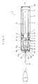
- FIG. 2 is a cross-sectional view for showing a configuration of the microphone.
- this embodiment of the invention exemplifies such a microphone that is built in the video camera, the invention is of course applicable to any other types of microphones.
- This video camera 100 includes a recording/reproducing section 102 provided on a body 101, a view finder section 103 provided on a side of the body 101, a lens section 104 provided at a tip of the body 101, and a microphone 1 provided on the body 101 toward its tip.
- the microphone 1 which is of a capacitor type, is comprised of a capacitor microphone unit (hereinafter called a microphone unit) 2, an amplification circuit board 3, a cylindrical housing 4, and an outer cylinder 5.
- the cylindrical housing 4 and the outer cylinder 5 are made of a conductor such as metal.
- the cylindrical housing 4 is cylindrical-shaped and has such a plurality of slits 6 formed in its peripheral surface along the axis that serves to give directivity to sound collection by the microphone 2. Note here that the cylindrical housing 4 may be polygonal in shape. Also note that only one slit 6 is shown in the cross-sectional view of FIG. 2.
- the microphone unit 2 and the amplification circuit board 3 are housed and disposed in the cylindrical housing 4.
- the amplification circuit board 3 is disposed on the side of one end of the cylindrical housing 4.
- the microphone unit 2 is disposed inner side than the amplification circuit board 3 along the axis of the cylindrical housing 4.
- the microphone unit 2 is supported and fixed on an inner peripheral surface of the cylindrical housing 4 with vibration preventing rubber 7 therebetween, which serves to block mechanical vibrations.
- a gap A is formed between the microphone unit 2 and the cylindrical housing 4 because they have the vibration preventing rubber 7 therebetween.
- An output terminal (not shown) of the microphone unit 2 and a ground terminal (not shown) are connected to corresponding input terminals (not shown) of amplification circuit board 3 through a lead wire 8.
- the outer cylinder 5 is a cylinder having a somewhat larger diameter than the cylindrical housing 4 and has such a plurality of slits, not shown, formed in its peripheral surface along the periphery that serves to give directivity to sound collection by the microphone 1. Note here that the outer cylinder 5 may be polygonal in shape.
- the cylindrical housing 4 is housed in the outer cylinder 5 as disposed coaxially therewith.
- the cylindrical housing 4 is supported and fixed on the inner peripheral surface of the outer cylinder 5 in a state where the mechanical vibrations are blocked through vibration preventing rubber 9. Between the cylindrical housing 4 and the outer cylinder 5 is disposed vibration preventing rubber 9 to thereby form a gap B.
- the outer cylinder 5 has a somewhat longer axial dimension than the cylindrical housing 4, so that the cylindrical housing 4 is disposed in such a state that its ends are positioned on the inner sides of the outer cylinder 5.
- An end 5a which is one of the two ends of the outer cylinder 5 and at which the amplification circuit board 3 is positioned is sealed by a lid 10 made of a conductor such as metal.
- the other end 5b of the outer cylinder 5 is sealed by a dust-proof mesh 11.
- the outer cylinder 5 and the lid 10 are directly connected with each other and so interconnected electrically.
- a microphone cable 12 for providing an output signal of the microphone 1 to the outside.
- the relay terminals 10a and 10b serve to relay an output signal of the amplification circuit board 3 to a conductor wire 12a of the microphone cable 12.
- the relay terminals 10a and 10b are provided in such a state that they are electrically insulated from the lid 10.
- an output terminal (not shown) of the amplification circuit board 3 via a lead wire 13.
- the conductor wire 12a of the microphone cable 12 is electrically connected to the relay terminals 10a and 10b.
- the output terminal of the amplification circuit board 3 and the conductor wire 12a of the microphone cable 12 are electrically interconnected through the relay terminals 10a and 10b.
- the relay terminal 10c is provided on the lid 10 in a state that it is electrically connected thereto.
- the relay terminal 10c serves to relay a grounding part (not shown) of the amplification circuit board 3 to a shield layer 12b of the microphone cable 12.
- To the relay terminal 10c is electrically connected the grounding part (not shown) of the amplification circuit board 3 via the lead wire 13.
- an insulation housing 12c thereof is peeled off to expose the shield layer 12b, so that when the microphone cable 12 passes through the lid 10, its shield layer 12b comes in contact with the lid 10 and is electrically connected therewith.
- an intermediary terminal may be inserted therebetween.
- the grounding part of the amplification circuit board 3 is electrically connected to the shield layer 12b of the microphone cable 12 via the lid 10 and the relay terminal 10c.
- the shield layer 12b is connected to the ground potential of the connection member.
- the grounding part of the amplification circuit board 3 is connected to the ground potential through the relay terminal 10c of the lid 10 and the shield layer 12b of the microphone cable 12.
- an intermediate connector 14 is provided around the peripheral surface of the microphone unit 2.
- the intermediate connector 14 is made of a conductor such as metal that has a sufficiently low electrical resistance of a few tens of ohms ( ⁇ ).
- the intermediate connector 14 is made of a plurality of short-hair-shaped members having conductivity and elasticity which is implanted in the peripheral surface of the microphone unit 2. More specifically, for example, the intermediate connector 14 is comprised of the plurality of minute-diameter short-hair-shaped members made of a conductor such as metal which is tied up into a bundle.
- the intermediate connector 14 is abutted directly against and so electrically connected to a grounding part (not shown) of the microphone unit 2.
- the intermediate connector 14 has a sufficiently large length than a radial dimension of the gap A and is disposed roughly radially outward of the cylindrical housing 4. With this, the tip of the intermediate member 14 comes in contact with the inner peripheral surface of the cylindrical housing 4. The tip of the intermediate connector 14 thus comes in contact with the inner peripheral surface of the cylindrical housing 4, to cause the grounding part of the microphone unit 2 to be electrically connected via the intermediate connector 14 to the cylindrical housing 4 with essentially the shortest distance.
- the intermediate connector 14 may be formed toward the microphone unit 2 on the inner peripheral surface of the cylinder housing 4.
- the intermediate connector 15 On the outer peripheral surface of the cylindrical housing 4 is provided another intermediate connector 15.
- the intermediate connector 15 is provided by tying up the plurality of minute-diameter short-hair-shaped members made of a conductor such as metal into a bundle.
- the intermediate connector 15 has a sufficiently larger length than a radial dimension of the gap B and is disposed radially outward of the cylindrical housing 4. This disposition causes the tip of the intermediate connector 15 to come in contact with the inner peripheral surface of the outer cylinder 5. The tip of the intermediate connector 15 thus comes in contact with the inner peripheral surface of the outer cylinder 5, to thereby electrically connect the cylinder housing 4 to the outer cylinder 5 with essentially the shortest distance. Also, the intermediate connectors 15 and 14 are disposed at the same position along the axis of the cylinder housing 4. This disposition causes the grounding part of the microphone 2 unit to be electrically connected to the outer cylinder 5 via the intermediate connector 14, the cylindrical housing 4, and the intermediate connector 15 with essentially the shortest distance.
- a grounding part (not shown) of the amplification circuit board 3 is provided on an end surface thereof, which comes in contact with the inner peripheral surface of the cylindrical housing 4 to thereby electrically connect the grounding part of the amplification circuit board 3 to the cylindrical housing 4 with essentially the shortest distance.
- the outer cylinder 5 is, as mentioned above, electrically connected via the lid 10 to the shield layer 12b of the microphone cable 12 to thereby electrically connect the outer cylinder 5 to the shield layer 12b with essentially the shortest distance. Accordingly, the microphone unit 2 and the cylindrical housing 4 are electrically connected through the outer cylinder 5 to the shield layer 12b of the microphone cable 12. Moreover, that connection distance is essentially the shortest mostly. It should be noted that the intermediate connector 15 may be disposed on the inner peripheral surface of the outer cylinder 5 toward the cylindrical housing 4.
- the intermediate connectors 14 and 15 can be configured as shown in FIG. 3, for example. That is, a plurality of conductive and elastic short-hair-shaped members 16 (which is made of metal, for example) is tied up with a fixing frame 17a into a hair bundle 17. This hair bundle 17 is in turn adhered and fixed with an adhesive tape 18 to the cylindrical housing 4 or the microphone unit 2, thus forming the intermediate connector 14 or 15.
- the fixing frame 17a or the adhesive tape 18 should be made of a conductor preferably in order to improve electrical connection.
- FIG. 3 exemplifies a fixed construction of the intermediate connector 15, the intermediate connector 14 may also be of the same construction, of course.
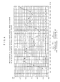
- the prior art product exhibits a rise in leakage output level of about up to -44 through -10dB of an SRL (standard recording level) in each frequency band (150-1000MHz).
- the microphone 1 according to this embodiment of the invention exhibits a mostly stable and very low leakage output level of about -55dB in every frequency band. This is considered because the invention has provided the intermediate connectors 14 and 15 in its configuration to thereby enable to decrease to the ground potential with essentially the shortest distance a high-frequency signal which occurs on the microphone unit 2, the cylindrical housing 4, and the outer cylinder 5 owing to an influence of a surrounding high electric field.
- the grounding part of the amplification circuit board 3 is connected via the cylindrical housing 4 to the ground potential with essentially the shortest distance, a high-frequency signal occurring at the amplification circuit board 3 can also be shirt-circuited to the ground potential efficiently, thus possibly suppressing the leakage output level by that much.
- the intermediate connectors 15 and 14 are provided at the same position along the axis of the cylindrical housing 4. This configuration enables to essentially minimize the length of a path from the connecting part of the microphone unit 2 to the ground terminal to thereby reduce the leakage output level to a minimum. At a high electric field of about 1000MHz, however, the same effect of leakage output level reduction can be given even if the intermediate connector 15 is provided at any axial position of the cylindrical housing 4.
- the gap B between the cylindrical housing 4 and the outer cylinder 5 encounters cavity resonance in a frequency band of a few tens of mega-hertz to a few giga-hertz according to a frequency of an electric field which occurs at the gap.
- the axial position of a region subject to such cavity resonance is determined by such a frequency. Therefore, by disposing the intermediate connector 15 at such a position subject to cavity resonance, the high-frequency signal occurring due to the cavity resonance can be decreased to the ground potential efficiently. Further, the intermediate connector 15 can be uniformly disposed at every axial position of the cylindrical housing 4. Then, high-frequency signals occurring corresponding to various frequencies owing to cavity resonance at any axial positions can be decreased to the ground potential efficiently. Moreover, the cylindrical housing 4 can also be connected to the ground potential with essentially the shortest distance.
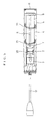
- intermediate connectors 20 and 21 may be used as made of a twist-reformed elongated conductor slice (e.g., metal slice) As shown in FIG.5.
- Such intermediate connectors 20 and 21 can also be electrically connected while blocking the mechanical vibrations.
- the microphone shown in FIG. 5 is basically of the same construction as the microphone 1 shown in FIG. 2, so that the same or similar elements are indicated by the same reference numerals and omitted in explanation.
- twist-reformed elongated conductor slice refers to the following, for example. That is, a conductor such as metal is cut into a slice, which is in turn twist-reformed into an elastic cylindrical spiral having a small diameter as a whole.
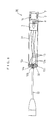
- FIG. 6 shows basically the same configuration of the directional microphone 1 of FIG. 2 except that there is no outer cylinder provided nor another intermediate member between the outer cylinder and the cylindrical housing and also somewhat except for the configuration of the cylindrical housing 31, so that the same or similar elements are indicated by the same reference numerals and omitted in explanation.
- a lid 32 is electrically connected to the shield layer 12b of the microphone cable 12and the cylindrical housing 31.
- the invention is applicable also to a dynamic microphone 40 shown in FIG. 7. That is, in this dynamic microphone 40, a permanent magnet core 41 and a movable coil 42 are housed and disposed in a cylindrical housing 43 made of a conductor with vibration preventing rubber 44 therebetween. Between the cylindrical housing 43 and the permanent magnet core 41 is provided an intermediate connector 45 similar to the above-mentioned intermediate connectors 14, 15, 20, and 21. Further, although not shown, a lid 46 has almost the same configuration as the above-mentioned lid 32.
- the vibration preventing rubber 7, 9, and 44 may be provided with conductivity (by mixing conductive particles into the rubber, for example) to thereby serve as the intermediate connector.
- the invention it is possible to securely inhibit an interference sound caused by a high electric field occurring at a portable telephone etc., thus realizing a microphone which is not liable to be influenced by the electromagnetic wave.
- the invention has proved to be able to provide a microphone having an electromagnetic-wave resistance good enough to accommodate the laws and regulations which are expected to become ever increasingly severer in many counties in order to prevent beforehand the disturbance due to malfunctioning of the electronic equipment owing to an influence of an electromagnetic wave.
Landscapes
- Physics & Mathematics (AREA)
- Engineering & Computer Science (AREA)
- Acoustics & Sound (AREA)
- Signal Processing (AREA)
- Details Of Audible-Bandwidth Transducers (AREA)
- Studio Devices (AREA)
Abstract
An intermediate connector (14) is provided between a
microphone unit (2) and a cylindrical housing (4). The
connector (14) electrically connects the grounding part of the
microphone unit (2) and the cylindrical housing (4)
substantially by the shortest path while blocking mechanical
vibrations. As a result, undesired high-frequency noises
attributed to surrounding strong electric field are removed.
Description
The invention relates to a microphone used in a video
camera etc.
There has conventionally been available such a
directional microphone used in a video camera etc. as follows.
That is, this microphone includes a capacitor microphone unit
and an amplification circuit board housed and disposed in a
cylindrical housing having a structure enhancing directivity
and also houses and disposes this cylindrical housing in an
outer cylinder. Between the cylindrical housing and the
capacitor microphone unit is sandwiched vibration preventing
rubber. Likewise, between the cylindrical housing and the
outer cylinder is also disposed vibration preventing rubber.
In such a configuration, an audio signal converted into an
electric signal by the capacitor microphone unit is amplified
by the amplification circuit board and then issued to the
outside. It should be noted that the cylindrical housing houses
a battery therein in some cases.
This prior art microphone, however, suffers from a
problem of occurrence of an interference sound caused by an
electromagnetic wave. The interference sound here refers to
the following. That is, it refers to a noise sound superimposed
on a recorded speech sound which occurs due to a high-frequency
component contained in an external electromagnetic wave when
the speech sound is recorded by a microphone.
With recent prevalence of portable telephones, there
have been increasing such cases that many unspecified persons
including reporters using a microphone use those portable
telephones in communication at a recording site requiring a
microphone. In particular, if a reporter uses his portable
telephone while recording a variety of speech sounds, he would
use his microphone and portable telephone in such a state where
they are very close to each other. Such a use situation of a
microphone may occur on an every-day basis in the future too
when a news site is reported using a video camera etc. having
a built-in microphone.
Although an influence of an electric field generated
by a portable telephone reaches relatively short, it is known
that in its vicinity (within a few to few tens of centimeters
therefrom), that field has a very high strength of a few tens
of volts/meter, which is a few tens of thousands of times as
much as that generated over the cities by a commercial radio
wave.
If a microphone and a portable telephone are used as
being very close to each other, an electromagnetic wave
generated by the portable telephone has a remarkable influence
on the microphone, so that an interference sound is mixed into
an audio signal. This is described specifically as follows.
A microphone can be considered to be an operation
circuit of an FET transistor the gate of which serves as a
diaphragm of a capacitor microphone unit. In the operation
circuit of such an FET transistor, a vibration generated by a
sound pressure of speech sound is captured as a potential
induced across an electret film which constitutes the
diaphragm. Accordingly, in the microphone, a sound-pressure
deviation is captured as a voltage deviation, which is in turn
taken in as a change in voltage input to the gate of the FET
transistor. The change in voltage input thus taken in is used
as an audio signal input to thereby operate the microphone.
If a high-frequency strong electric field occurs near
a microphone unit having such characteristics, a nonlinear
distortion occurs in an input/output circuit or other electric
circuits of the electret film or FET transistors, so that an
envelope detected-wave output of a frequency-modulated,
amplitude-modulated, and digital-modulated high-frequency
signals appears in an audio band. Further, a similar
detected-wave output appears also at a subsequent-stage
amplification circuit board. Such a detected-wave output gives
rise to various high-frequency interference sounds in the audio
signal.
The recent prevalence of portable telephones has been
shifting a service frequency band toward a higher frequency
side (e.g., 1.5GHz), so that presently an influence of
electromagnetic waves on such a microphone is becoming more and
more remarkable. Accordingly, there is desired such a
microphone that is not easily influenced by electromagnetic
waves.
Also, to prevent beforehand any disturbance due to
malfunction etc. of a variety of electronic apparatuses caused
by an electromagnetic wave, many counties have laws and
regulations of the electromagnetic-wave resistance of such
electronic equipment. One example is CE (Conformite
Eoropeenne) in Europe. Further, with prevalence of high-electromagnetic-wave
generators used by individuals
represented by a portable telephone, many countries are trying
to prevent beforehand the future-expected disturbance caused
by an electromagnetic wave by further tightening those laws and
regulations so that only such products that have a higher
electromagnetic-wave resistance may be allowed to circulate in
the world markets. In view of such a status quo, the microphone
is also desired to have an even higher electromagnetic-wave
resistance.
To solve the above-mentioned problems, the prior-art
microphone is also provided with a grounding path for
connecting a grounding part thereof to the ground. This
grounding path, however, is comprised of a lead wire for
interconnecting the microphone unit and the amplification
circuit board, a grounding wiring line in the amplification
circuit board, and a lead wire for interconnecting the
amplification circuit board and a microphone cable, so that it
cannot be the shortest path effective enough to remove an
interference sound caused by a high-frequency electric field.
In view of the above, it is an object of the invention
to provide a microphone unit which can effectively remove an
interference sound caused by a high-frequency electric field.
A microphone or a video camera according to the
invention includes a microphone unit, a cylindrical housing
made of a conductor for housing the microphone unit, and an
intermediate connector which electrically connects a grounding
part of the microphone unit to the cylindrical housing along
essentially the shortest path while blocking mechanical
vibrations. In this configuration, it operates as follows.
Even if an electric field induced by an electromagnetic
wave present around the microphone is formed in the cylindrical
housing to correspondingly cause such a high-frequency signal
to occur in the microphone unit that contains a modified signal
which gives an interference sound to the microphone, the
high-frequency signal is led through the intermediate
connector to the cylindrical housing along essentially the
shortest distance. By grounding the cylindrical housing
beforehand, therefore, such a high-frequency signal occurring
at the microphone unit can be securely discharged to the ground
through the cylindrical housing. Moreover, the cylindrical
housing, which is a conductor having a simple construction and
also which has a vibration preventing mechanism between itself
and an outer cylinder, serves to connect the microphone unit
to the ground potential therethrough along essentially the
shortest path not longer than necessary. This configuration
enables to securely decrease the interference sound caused by
such a high-frequency signal as mentioned above.
It should be noted that the cylindrical housing has a
simple construction and so is liable to be exposed to the
outside at part of a peripheral surface or end thereof, so that
it can be grounded relatively easily.
Also, the above-mentioned improved microphone of the
invention further includes a supporting member for supporting
the microphone unit in the cylindrical housing while blocking
mechanical vibrations . Specifically, the following operations
are carried out.
Although the microphone having the supporting member
can prevent a high-frequency signal (which contains a modulated
signal interfering the microphone) caused by mechanical
vibrations of the cylindrical housing from occurring at the
microphone unit, it is difficult construction-wise to
electrically interconnect the microphone unit and the
cylindrical housing using the supporting member. Accordingly,
if the supporting member is integrated with the intermediate
connector, the microphone unit can be supported and fixed in
the cylindrical housing while preventing the high-frequency
signal from occurring.
Also, in the improved microphone of the invention, the
intermediate connector is made of an elastic short-hair-shaped
conducting member, which itself is protruded from either one
of the microphone unit and the cylindrical housing as having
its tip abutted against the other. In this configuration, the
following is possible.
The short-hair-shaped conducting member can give a
sufficient function required on the intermediate connector of
electrically interconnecting the two while blocking the
mechanical vibrations and also can be mounted relatively
simply.
Also, in the improved microphone of the invention, the
intermediate connector is made of an elongated conducting slice
which is twist-reformed. This has the following effects.
The twist-reformed elongated conducting slice can give
a sufficient function required on the intermediate connector
of electrically interconnecting the two while blocking the
mechanical vibrations and also can be mounted relatively
easily.
Also, in the improved microphone of the invention, the
amplification circuit board for amplifying an output signal of
the microphone unit is housed in the cylindrical housing and
also has its grounding part electrically connected to the
cylindrical housing along essentially the shortest distance.
This has the following effects.
It is possible to discharge through the cylindrical
housing to the ground such a high-frequency signal which may
possibly occur, due to an electromagnetic wave present around
the microphone, in the amplification circuit board that
contains a modified signal which may give an interference sound
to the microphone.
Also, the improved microphone of the invention further
includes a lid made of a conductor which seals the end of the
cylindrical housing and also electrically connected thereto
and a microphone cable which passes through the lid from the
inside to the outside of the cylindrical housing for providing
an output signal of the microphone to the outside in such a
configuration that a shield layer of the microphone cable is
electrically connected to the lid. This has the following
effects.
The cylindrical housing can be electrically connected
through the lid to the shield layer of the microphone cable,
thus connecting the cylindrical housing to the ground potential
easily and along the shortest distance.
Also, the improved microphone of the invention further
includes an outer cylinder made of a conductor for surrounding
the peripheral surface of the cylindrical housing and another
intermediate connector for electrically interconnecting the
cylindrical housing and the outer cylinder with essentially the
shortest distance while blocking the mechanical vibrations.
This has the following effects.
If an electric field is formed, due to an
electromagnetic wave present around the microphone, at a gap
between the cylindrical housing and the outer cylinder, such
a high-frequency signal corresponding to the electric field may
occur on the microphone unit, the cylindrical housing or the
outer cylinder that contains a modulated signal giving an
interference sound to the microphone. Thus generated high-frequency
signal, however, passes through the former
intermediate connector and the another intermediate connector
to the cylindrical housing or the outer cylinder. Accordingly,
by connecting the cylindrical housing or the outer cylinder to
the ground potential, the high-frequency signal can be securely
decreased through the cylindrical housing or the outer cylinder
to the ground potential. Moreover, the cylindrical housing or
the outer cylinder, which is made of a conductor having a simple
construction, is used to ground the microphone therethrough,
thus enabling essentially minimizing a path in length not
longer than necessary between the microphone unit and the
ground potential. This also contributes to mitigating of the
high-frequency signal. Also, the outer cylinder, like the
cylindrical housing, is simple in construction and has often
part of the peripheral surface thereof exposed to the outside,
thus enabling connecting the outer cylinder to the ground
potential relatively easily.
Also, the improved microphone of the invention further
includes another supporting member for supporting the
cylindrical housing in the outer cylinder while blocking the
mechanical vibrations. This has the following effects.
Although the microphone having such a supporting member
can prevent a high-frequency signal (which contains a modulated
signal giving an interference sound to the microphone) caused
by mechanical vibrations of the outer cylinder from occurring
at the microphone unit, it is difficult construction-wise to
electrically interconnect the microphone unit and the outer
cylinder using the another supporting member. Accordingly,
another intermediate connector and a further supporting member
may be provided to thereby support and fix the cylindrical
housing in the outer cylinder while preventing the occurrence
of an interference sound due to the high-frequency signal.
Also, in the improved microphone of the invention, the
another intermediate connector is made of an elastic short-hair-shaped
conducting member, which is protruded from either
one of the cylindrical housing and the outer cylinder as having
its tip as abutted against the other. This has the following
effects.
The short-hair-shaped conducting member can
sufficiently have a function required on the another
intermediate connector of electrically interconnecting the two
with essentially the shortest distance while blocking the
mechanical vibrations and also can be mounted relatively
easily.
Also, in the improved microphone of the invention, the
another intermediate connector is made of a twist-reformed
elongated conducting slice. This has the following effects.
This twist-reformed elongated conducting slice can
sufficiently have a function required on the another
intermediate connector of electrically interconnecting the two
while blocking the mechanical vibrations and also can be
mounted relatively easily.
Also, in the improved microphone of the invention, the
intermediate connector and the another intermediate connector
are disposed at the same position along the axis of the
cylindrical housing. This has the following effects.
It is possible to interconnect the microphone unit, the
cylindrical housing, and the outer cylinder to the ground
potential with the shortest distance without a detour. This
enables to securely decrease a high-frequency signal, (which
contains a modulated signal giving an interference sound to the
microphone) which occurs on the microphone unit, the
cylindrical housing or the outer cylinder, to the ground
potential.
Also, in the improved microphone of the invention, the
another intermediate connector is uniformly arranged at the gap
between the cylindrical housing and the outer cylinder. This
has the following effects.
Such a path can be naturally formed of the another
intermediate connector thus uniformly arranged at the gap that
can connect the cylindrical housing and the outer cylinder to
the ground potential with essentially the shortest distance
without a detour. This enables to securely decrease to the
ground potential a high-frequency signal (which contains a
modulated signal giving an interference sound to the
microphone) which occurs at the microphone unit, the
cylindrical housing, or the outer cylinder.
Also, a further intermediate connector is disposed at
such a position in the gap between the cylindrical housing and
the outer cylinder that is subject to cavity resonance. This
enables to securely decrease to the ground potential a
high-frequency signal (which contains a modulated signal
giving an interference sound to the microphone) which occurs
due to cavity resonance.
Also, in the improved microphone of the invention, the
further intermediate connector is disposed at such a position
in the microphone that is subject to cavity resonance. This
has the following effects. A high-frequency signal caused by
cavity resonance can be securely decreased to the ground
potential. It should be noted that cavity resonance referred
to the above-mentioned aspects is supposed to have a frequency
from a few tens of mega-hertz to a few giga-hertz.
Also, the improved microphone of the invention further
includes a lid made of a conductor which seals the end of the
outer cylinder as electrically connected thereto and a
microphone cable which passes through the lid from the inside
to the outside of the outer cylinder for providing an output
signal of the microphone to the outside in such a configuration
that a shield layer of the microphone cable and the lid are
electrically connected with each other. This has the following
effects.
The cylindrical housing can be electrically connected
through the lid to the shield layer of the microphone cable,
to connect the outer cylinder to the ground potential easily
and with the shortest distance.
The following will describe in detail a best embodiment
of the invention with reference to the drawings.
FIG. 1 is a schematic diagram for showing a
configuration of a video camera which a microphone related to
the best embodiment of the invention is built in and FIG. 2 is
a cross-sectional view for showing a configuration of the
microphone. Although this embodiment of the invention
exemplifies such a microphone that is built in the video camera,
the invention is of course applicable to any other types of
microphones.
This video camera 100 includes a recording/reproducing
section 102 provided on a body 101, a view finder section 103
provided on a side of the body 101, a lens section 104 provided
at a tip of the body 101, and a microphone 1 provided on the
body 101 toward its tip.
As shown in FIG. 2, the microphone 1, which is of a
capacitor type, is comprised of a capacitor microphone unit
(hereinafter called a microphone unit) 2, an amplification
circuit board 3, a cylindrical housing 4, and an outer cylinder
5. The cylindrical housing 4 and the outer cylinder 5 are made
of a conductor such as metal.
The cylindrical housing 4 is cylindrical-shaped and has
such a plurality of slits 6 formed in its peripheral surface
along the axis that serves to give directivity to sound
collection by the microphone 2. Note here that the cylindrical
housing 4 may be polygonal in shape. Also note that only one
slit 6 is shown in the cross-sectional view of FIG. 2.
The microphone unit 2 and the amplification circuit
board 3 are housed and disposed in the cylindrical housing 4.
The amplification circuit board 3 is disposed on the side of
one end of the cylindrical housing 4. The microphone unit 2
is disposed inner side than the amplification circuit board 3
along the axis of the cylindrical housing 4. Specifically, the
microphone unit 2 is supported and fixed on an inner peripheral
surface of the cylindrical housing 4 with vibration preventing
rubber 7 therebetween, which serves to block mechanical
vibrations. A gap A is formed between the microphone unit 2
and the cylindrical housing 4 because they have the vibration
preventing rubber 7 therebetween. An output terminal (not
shown) of the microphone unit 2 and a ground terminal (not
shown) are connected to corresponding input terminals (not
shown) of amplification circuit board 3 through a lead wire 8.
The outer cylinder 5 is a cylinder having a somewhat
larger diameter than the cylindrical housing 4 and has such a
plurality of slits, not shown, formed in its peripheral surface
along the periphery that serves to give directivity to sound
collection by the microphone 1. Note here that the outer
cylinder 5 may be polygonal in shape. The cylindrical housing
4 is housed in the outer cylinder 5 as disposed coaxially
therewith. The cylindrical housing 4 is supported and fixed
on the inner peripheral surface of the outer cylinder 5 in a
state where the mechanical vibrations are blocked through
vibration preventing rubber 9. Between the cylindrical housing
4 and the outer cylinder 5 is disposed vibration preventing
rubber 9 to thereby form a gap B. The outer cylinder 5 has a
somewhat longer axial dimension than the cylindrical housing
4, so that the cylindrical housing 4 is disposed in such a state
that its ends are positioned on the inner sides of the outer
cylinder 5.
An end 5a, which is one of the two ends of the outer
cylinder 5 and at which the amplification circuit board 3 is
positioned is sealed by a lid 10 made of a conductor such as
metal. The other end 5b of the outer cylinder 5 is sealed by
a dust-proof mesh 11. The outer cylinder 5 and the lid 10 are
directly connected with each other and so interconnected
electrically.
At the radial center of the lid 10 is inserted and fixed
one end of a microphone cable 12 for providing an output signal
of the microphone 1 to the outside. On the inner surface of
the lid 10 are provided relay terminals 10a, 10b, and 10c. The
relay terminals 10a and 10b serve to relay an output signal of
the amplification circuit board 3 to a conductor wire 12a of
the microphone cable 12. Although not shown, the relay
terminals 10a and 10b are provided in such a state that they
are electrically insulated from the lid 10. To the relay
terminals 10a and 10b is electrically connected an output
terminal (not shown) of the amplification circuit board 3 via
a lead wire 13. Further, the conductor wire 12a of the
microphone cable 12 is electrically connected to the relay
terminals 10a and 10b. In such a configuration, the output
terminal of the amplification circuit board 3 and the conductor
wire 12a of the microphone cable 12 are electrically
interconnected through the relay terminals 10a and 10b.
Although not shown, the relay terminal 10c is provided
on the lid 10 in a state that it is electrically connected
thereto. The relay terminal 10c serves to relay a grounding
part (not shown) of the amplification circuit board 3 to a
shield layer 12b of the microphone cable 12. To the relay
terminal 10c is electrically connected the grounding part (not
shown) of the amplification circuit board 3 via the lead wire
13. Further, at en end of the microphone cable 12 on the side
of the lid, an insulation housing 12c thereof is peeled off to
expose the shield layer 12b, so that when the microphone cable
12 passes through the lid 10, its shield layer 12b comes in
contact with the lid 10 and is electrically connected
therewith. It should be noted that to secure electrical
connected between the shield layer 12b and the lid 10, an
intermediary terminal, not shown, may be inserted
therebetween. In such a configuration, the grounding part of
the amplification circuit board 3 is electrically connected to
the shield layer 12b of the microphone cable 12 via the lid 10
and the relay terminal 10c. With this, when the microphone
cable 12 is connected to a connection member (not shown) of the
microphone 1, the shield layer 12b is connected to the ground
potential of the connection member. Thus, the grounding part
of the amplification circuit board 3 is connected to the ground
potential through the relay terminal 10c of the lid 10 and the
shield layer 12b of the microphone cable 12.
The following will describe a configuration which
features this microphone 1. In this microphone 1, an
intermediate connector 14 is provided around the peripheral
surface of the microphone unit 2. The intermediate connector
14 is made of a conductor such as metal that has a sufficiently
low electrical resistance of a few tens of ohms (Ω).
Specifically, the intermediate connector 14 is made of a
plurality of short-hair-shaped members having conductivity and
elasticity which is implanted in the peripheral surface of the
microphone unit 2. More specifically, for example, the
intermediate connector 14 is comprised of the plurality of
minute-diameter short-hair-shaped members made of a conductor
such as metal which is tied up into a bundle.
The intermediate connector 14 is abutted directly
against and so electrically connected to a grounding part (not
shown) of the microphone unit 2. The intermediate connector
14 has a sufficiently large length than a radial dimension of
the gap A and is disposed roughly radially outward of the
cylindrical housing 4. With this, the tip of the intermediate
member 14 comes in contact with the inner peripheral surface
of the cylindrical housing 4. The tip of the intermediate
connector 14 thus comes in contact with the inner peripheral
surface of the cylindrical housing 4, to cause the grounding
part of the microphone unit 2 to be electrically connected via
the intermediate connector 14 to the cylindrical housing 4 with
essentially the shortest distance. Note here that the
intermediate connector 14 may be formed toward the microphone
unit 2 on the inner peripheral surface of the cylinder housing
4.
On the outer peripheral surface of the cylindrical
housing 4 is provided another intermediate connector 15. The
intermediate connector 15, like the intermediate connector 14,
is comprised of a plurality of elastic short-hair-shaped
members with a sufficiently low electrical resistance which is
implanted in the peripheral surface of the cylindrical housing
4. Specifically, like the intermediate connector 14, for
example, the intermediate connector 15 is provided by tying up
the plurality of minute-diameter short-hair-shaped members
made of a conductor such as metal into a bundle.
The intermediate connector 15 has a sufficiently larger
length than a radial dimension of the gap B and is disposed
radially outward of the cylindrical housing 4. This
disposition causes the tip of the intermediate connector 15 to
come in contact with the inner peripheral surface of the outer
cylinder 5. The tip of the intermediate connector 15 thus comes
in contact with the inner peripheral surface of the outer
cylinder 5, to thereby electrically connect the cylinder
housing 4 to the outer cylinder 5 with essentially the shortest
distance. Also, the intermediate connectors 15 and 14 are
disposed at the same position along the axis of the cylinder
housing 4. This disposition causes the grounding part of the
microphone 2 unit to be electrically connected to the outer
cylinder 5 via the intermediate connector 14, the cylindrical
housing 4, and the intermediate connector 15 with essentially
the shortest distance.
A grounding part (not shown) of the amplification
circuit board 3 is provided on an end surface thereof, which
comes in contact with the inner peripheral surface of the
cylindrical housing 4 to thereby electrically connect the
grounding part of the amplification circuit board 3 to the
cylindrical housing 4 with essentially the shortest distance.
The outer cylinder 5 is, as mentioned above,
electrically connected via the lid 10 to the shield layer 12b
of the microphone cable 12 to thereby electrically connect the
outer cylinder 5 to the shield layer 12b with essentially the
shortest distance. Accordingly, the microphone unit 2 and the
cylindrical housing 4 are electrically connected through the
outer cylinder 5 to the shield layer 12b of the microphone cable
12. Moreover, that connection distance is essentially the
shortest mostly. It should be noted that the intermediate
connector 15 may be disposed on the inner peripheral surface
of the outer cylinder 5 toward the cylindrical housing 4.
The intermediate connectors 14 and 15 can be configured
as shown in FIG. 3, for example. That is, a plurality of
conductive and elastic short-hair-shaped members 16 (which is
made of metal, for example) is tied up with a fixing frame 17a
into a hair bundle 17. This hair bundle 17 is in turn adhered
and fixed with an adhesive tape 18 to the cylindrical housing
4 or the microphone unit 2, thus forming the intermediate
connector 14 or 15. Note here that the fixing frame 17a or the
adhesive tape 18 should be made of a conductor preferably in
order to improve electrical connection. Also, although FIG.
3 exemplifies a fixed construction of the intermediate
connector 15, the intermediate connector 14 may also be of the
same construction, of course.
The following will describe a result of measuring a
leakage output (interference sound output)of a modulated sound
when this microphone 1 was disposed in an environment of a
strong electric field of a frequency of 100-1000MHz (30V/m
calculated as electric field strength) and a modulation
frequency of 1kHz/80% along with a measurement result of a prior
art microphone with reference to FIG. 4. In FIG. 4, the
horizontal axis indicates a frequency (MHz) and a vertical
axis, a leakage output (dB).
As may be clear from FIG. 4, the prior art product
exhibits a rise in leakage output level of about up to -44
through -10dB of an SRL (standard recording level) in each
frequency band (150-1000MHz). In contrast, the microphone 1
according to this embodiment of the invention exhibits a mostly
stable and very low leakage output level of about -55dB in every
frequency band. This is considered because the invention has
provided the intermediate connectors 14 and 15 in its
configuration to thereby enable to decrease to the ground
potential with essentially the shortest distance a high-frequency
signal which occurs on the microphone unit 2, the
cylindrical housing 4, and the outer cylinder 5 owing to an
influence of a surrounding high electric field. Further, since
the grounding part of the amplification circuit board 3 is
connected via the cylindrical housing 4 to the ground potential
with essentially the shortest distance, a high-frequency
signal occurring at the amplification circuit board 3 can also
be shirt-circuited to the ground potential efficiently, thus
possibly suppressing the leakage output level by that much.
Note here that in this microphone 1, the intermediate
connectors 15 and 14 are provided at the same position along
the axis of the cylindrical housing 4. This configuration
enables to essentially minimize the length of a path from the
connecting part of the microphone unit 2 to the ground terminal
to thereby reduce the leakage output level to a minimum. At
a high electric field of about 1000MHz, however, the same effect
of leakage output level reduction can be given even if the
intermediate connector 15 is provided at any axial position of
the cylindrical housing 4.
Also, the gap B between the cylindrical housing 4 and
the outer cylinder 5 encounters cavity resonance in a frequency
band of a few tens of mega-hertz to a few giga-hertz according
to a frequency of an electric field which occurs at the gap.
The axial position of a region subject to such cavity resonance
is determined by such a frequency. Therefore, by disposing the
intermediate connector 15 at such a position subject to cavity
resonance, the high-frequency signal occurring due to the
cavity resonance can be decreased to the ground potential
efficiently. Further, the intermediate connector 15 can be
uniformly disposed at every axial position of the cylindrical
housing 4. Then, high-frequency signals occurring
corresponding to various frequencies owing to cavity resonance
at any axial positions can be decreased to the ground potential
efficiently. Moreover, the cylindrical housing 4 can also be
connected to the ground potential with essentially the shortest
distance.
Besides the intermediate connectors 14 and 15 made of
such a short-hair-shaped member as shown in FIG. 2, such
intermediate connectors 20 and 21 may be used as made of a
twist-reformed elongated conductor slice (e.g., metal slice)
As shown in FIG.5. Such intermediate connectors 20 and 21 can
also be electrically connected while blocking the mechanical
vibrations. The microphone shown in FIG. 5 is basically of the
same construction as the microphone 1 shown in FIG. 2, so that
the same or similar elements are indicated by the same reference
numerals and omitted in explanation.
Here, the twist-reformed elongated conductor slice
refers to the following, for example. That is, a conductor such
as metal is cut into a slice, which is in turn twist-reformed
into an elastic cylindrical spiral having a small diameter as
a whole.
In the above embodiment, although the invention has
been applied to the directional microphone 1 having the
cylindrical housing 4 and the outer cylinder 5, the invention
is applicable also to a non-directional microphone 30 which has
only a cylindrical housing 31 but does not have an outer
cylinder shown in FIG. 6. Note here that FIG. 6 shows basically
the same configuration of the directional microphone 1 of FIG.
2 except that there is no outer cylinder provided nor another
intermediate member between the outer cylinder and the
cylindrical housing and also somewhat except for the
configuration of the cylindrical housing 31, so that the same
or similar elements are indicated by the same reference
numerals and omitted in explanation. A lid 32, however, is
electrically connected to the shield layer 12b of the
microphone cable 12and the cylindrical housing 31.
The invention is applicable also to a dynamic
microphone 40 shown in FIG. 7. That is, in this dynamic
microphone 40, a permanent magnet core 41 and a movable coil
42 are housed and disposed in a cylindrical housing 43 made of
a conductor with vibration preventing rubber 44 therebetween.
Between the cylindrical housing 43 and the permanent magnet
core 41 is provided an intermediate connector 45 similar to the
above-mentioned intermediate connectors 14, 15, 20, and 21.
Further, although not shown, a lid 46 has almost the same
configuration as the above-mentioned lid 32.
Although the above-mentioned embodiment has used a
short-hair-shaped member or a twist-reformed elongated
conductor slice to make up the intermediate connectors 14, 15,
20, 21, and 45, the vibration preventing rubber 7, 9, and 44
may be provided with conductivity (by mixing conductive
particles into the rubber, for example) to thereby serve as the
intermediate connector.
According to the invention, it is possible to securely
inhibit an interference sound caused by a high electric field
occurring at a portable telephone etc., thus realizing a
microphone which is not liable to be influenced by the
electromagnetic wave.
Also, the invention has proved to be able to provide
a microphone having an electromagnetic-wave resistance good
enough to accommodate the laws and regulations which are
expected to become ever increasingly severer in many counties
in order to prevent beforehand the disturbance due to
malfunctioning of the electronic equipment owing to an
influence of an electromagnetic wave.
Claims (15)
- A microphone comprising:a microphone unit;a cylindrical housing made of a conductor for housing said microphone unit; andan intermediate connector for electrically connecting a grounding part of said microphone unit to said cylindrical housing with essentially the shortest distance while blocking mechanical vibrations.
- The microphone according to Claim 1, further comprising a supporting member for supporting said microphone unit in said cylindrical housing while blocking mechanical vibrations.
- The microphone according to Claim 1, wherein said intermediate connector is made of an elastic short-hair-shaped conducting member, which is protruded out from either one of said microphone unit and said cylindrical housing as having a tip thereof abutted against the other.
- The microphone according to Claim 1, wherein said intermediate connector is made of a twist-reformed elongated conductor slice.
- The microphone according to Claim 1, wherein an amplification circuit board for amplifying an output signal of said microphone unit is housed in said cylindrical housing and has a grounding part thereof electrically connected to said cylindrical housing with essentially the shortest distance.
- The microphone according to Claim 1, further comprising:wherein a shield layer of said microphone cable and said lid are interconnected electrically.a lid made of a conductor for sealing an end of said cylindrical housing as electrically connected thereto; anda microphone cable disposed so as to pass through said lid from an inside to an outside of said cylindrical housing, thus leading an output signal of said microphone to an outside,
- The microphone according to Claim 1, further comprising:an outer cylinder made of a conductor for surrounding a peripheral surface of said cylindrical housing; andanother intermediate connector for electrically connecting said cylindrical housing to said outer cylinder with essentially the shortest distance while blocking mechanical vibrations.
- The microphone according to Claim 7, further comprising another supporting member for supporting said cylindrical housing in said outer cylinder while blocking mechanical vibrations.
- The microphone according to Claim 7, said another intermediate connector is made of an elastic short-hair-shaped conductive member, which is protruded out from either one of said cylindrical housing and said outer cylinder as having a tip thereof abutted against the other.
- The microphone according to Claim 7, wherein said another intermediate connector is made of a twist-reformed elongated conductor slice.
- The microphone according to Claim 7, wherein said intermediate connector and said another intermediate connector are disposed at the same position along an axis of the cylindrical housing.
- The microphone according to Claim 7, wherein said another intermediate connector is uniformly disposed at a gap between said cylindrical housing and said outer cylinder.
- The microphone according to Claim 7, wherein said another intermediate connector is disposed at such a position that has a high possibility of cavity resonance occurring in the microphone.
- The microphone according to Claim 7, further comprising:wherein a shield layer of said microphone cable and said lid are interconnected electrically.a lid made of a conductor for sealing an edge of said outer cylinder as electrically connected thereto; anda microphone cable disposed so as to pass through said lid from an inside to an outside of said outer cylinder for leading an output signal of the microphone to an outside,
- A video camera comprising a microphone, said microphone including:a microphone unit;a cylindrical housing made of a conductor for housing said microphone unit; andan intermediate connector for electrically connecting a grounding part of said microphone unit to said cylindrical housing with essentially the shortest distance while blocking mechanical vibrations.
Applications Claiming Priority (3)
| Application Number | Priority Date | Filing Date | Title |
|---|---|---|---|
| JP27906999A JP2001103591A (en) | 1999-09-30 | 1999-09-30 | Microphone and video camera |
| JP27906999 | 1999-09-30 | ||
| PCT/JP2000/006811 WO2001024573A1 (en) | 1999-09-30 | 2000-09-29 | Microphone and video camera |
Publications (2)
| Publication Number | Publication Date |
|---|---|
| EP1217870A1 true EP1217870A1 (en) | 2002-06-26 |
| EP1217870A4 EP1217870A4 (en) | 2006-10-18 |
Family
ID=17605991
Family Applications (1)
| Application Number | Title | Priority Date | Filing Date |
|---|---|---|---|
| EP00963014A Withdrawn EP1217870A4 (en) | 1999-09-30 | 2000-09-29 | MICROPHONE AND VIDEO CAMERA |
Country Status (5)
| Country | Link |
|---|---|
| US (1) | US6721432B1 (en) |
| EP (1) | EP1217870A4 (en) |
| JP (1) | JP2001103591A (en) |
| CN (1) | CN1205837C (en) |
| WO (1) | WO2001024573A1 (en) |
Families Citing this family (13)
| Publication number | Priority date | Publication date | Assignee | Title |
|---|---|---|---|---|
| KR100628569B1 (en) * | 2002-02-09 | 2006-09-26 | 삼성전자주식회사 | Camcorders that can combine multiple sound acquisition devices |
| US7245995B2 (en) * | 2003-02-19 | 2007-07-17 | Robert Bosch Gmbh | Fault-tolerant vehicle stability control |
| JP4613047B2 (en) * | 2004-10-27 | 2011-01-12 | 株式会社オーディオテクニカ | Condenser microphone |
| JP4562032B2 (en) * | 2005-01-19 | 2010-10-13 | 株式会社オーディオテクニカ | Condenser microphone |
| JP4560424B2 (en) * | 2005-02-24 | 2010-10-13 | 株式会社オーディオテクニカ | Condenser microphone |
| USD573588S1 (en) * | 2006-10-26 | 2008-07-22 | Knowles Electronic, Llc | Assistive listening device |
| USD605183S1 (en) * | 2007-11-02 | 2009-12-01 | Sennheiser Electronic Gmbh & Co. Kg | Microphone |
| USD603381S1 (en) * | 2007-11-02 | 2009-11-03 | Sennheiser Electronic Gmbh & Co. Kg | Microphone |
| AU352579S (en) * | 2013-11-14 | 2013-11-29 | Freedman Electronics Pty Ltd | Microphone line tube |
| JP6521601B2 (en) * | 2014-10-03 | 2019-05-29 | キヤノン株式会社 | Cylindrical body holding device |
| USD889442S1 (en) * | 2018-06-19 | 2020-07-07 | G.R.A.S. Sound & Vibration A/S | Microphone |
| USD881168S1 (en) * | 2018-11-09 | 2020-04-14 | Ching-Wen Chen | Straight mini microphone |
| USD890729S1 (en) * | 2019-01-09 | 2020-07-21 | Ching-Wen Chen | Multi-purpose microphone |
Family Cites Families (12)
| Publication number | Priority date | Publication date | Assignee | Title |
|---|---|---|---|---|
| GB246351A (en) * | 1925-04-03 | 1926-01-28 | Lee De Forest | Shielding microphones and associated amplifier apparatus |
| US1805362A (en) * | 1929-10-09 | 1931-05-12 | Hugh J Ellis | Microphone and microphone mounting |
| GB362639A (en) * | 1930-11-17 | 1931-12-10 | Jenkins & Adair Inc | Improvement in condenser telephone transmitter apparatus |
| US3201530A (en) * | 1961-09-12 | 1965-08-17 | Ling Temco Vought Inc | Modular component assembly of microphones |
| AT370580B (en) * | 1981-06-04 | 1983-04-11 | Akg Akustische Kino Geraete | BRACKET FOR ROD OR TUBULAR, VIBRATION-SENSITIVE ITEMS, IN PARTICULAR FOR MICROPHONES |
| AT371656B (en) * | 1981-09-24 | 1983-07-25 | Akg Akustische Kino Geraete | STORAGE FOR ELECTROACOUSTIC TRANSDUCERS |
| JPS58155186U (en) * | 1982-04-12 | 1983-10-17 | 日立電子株式会社 | Support structure of microphone unit for television camera |
| JPH0715262Y2 (en) * | 1988-11-07 | 1995-04-10 | ホシデン株式会社 | Microphone unit mounting structure |
| JPH0829504B2 (en) | 1989-06-21 | 1996-03-27 | 日本ニューマチック工業株式会社 | Vibrating tool |
| DE69120602T2 (en) * | 1990-05-14 | 1996-11-21 | Gold Star Co., Ltd., Seoul/Soul | Camera recorder |
| KR930008192Y1 (en) * | 1990-12-24 | 1993-12-10 | 주식회사 금성사 | Camcorder with directing microphone |
| JP3026474U (en) * | 1995-12-28 | 1996-07-12 | 株式会社オーディオテクニカ | Line microphone |
-
1999
- 1999-09-30 JP JP27906999A patent/JP2001103591A/en active Pending
-
2000
- 2000-09-29 WO PCT/JP2000/006811 patent/WO2001024573A1/en not_active Ceased
- 2000-09-29 CN CNB008090505A patent/CN1205837C/en not_active Expired - Lifetime
- 2000-09-29 EP EP00963014A patent/EP1217870A4/en not_active Withdrawn
- 2000-09-29 US US10/089,379 patent/US6721432B1/en not_active Expired - Lifetime
Also Published As
| Publication number | Publication date |
|---|---|
| US6721432B1 (en) | 2004-04-13 |
| EP1217870A4 (en) | 2006-10-18 |
| WO2001024573A1 (en) | 2001-04-05 |
| CN1356013A (en) | 2002-06-26 |
| CN1205837C (en) | 2005-06-08 |
| JP2001103591A (en) | 2001-04-13 |
Similar Documents
| Publication | Publication Date | Title |
|---|---|---|
| US6721432B1 (en) | Microphone and video camera | |
| CN100544501C (en) | Electret capacitor microphone | |
| US8428285B2 (en) | Microphone screen with common mode interference reduction | |
| US7292700B1 (en) | Microphone for a hearing aid | |
| JP5409430B2 (en) | Gooseneck condenser microphone | |
| FI115089B (en) | Elastomeric adapter | |
| JP2008187581A (en) | Boundary microphone | |
| JP5586518B2 (en) | Gooseneck condenser microphone | |
| US8116498B2 (en) | Condenser microphone | |
| JP4560380B2 (en) | Condenser microphone output connector | |
| US7526097B2 (en) | Condenser microphone | |
| JP2006074149A (en) | Condenser microphone unit | |
| US7599505B2 (en) | Condenser microphone | |
| JP4573642B2 (en) | Condenser microphone | |
| US20060046538A1 (en) | Microphone and microphone shield | |
| JP4310234B2 (en) | Condenser microphone | |
| US7697708B2 (en) | Condenser microphone | |
| JP4716818B2 (en) | Condenser microphone | |
| JP5660767B2 (en) | Condenser microphone | |
| JP4810315B2 (en) | Condenser microphone | |
| JP2010050866A (en) | Unidirectional capacitor microphone | |
| JP2002165296A (en) | Electrostatic transducer | |
| CN1816942A (en) | An apparatus for radio reception | |
| JP2011141971A (en) | Coaxial connector and high frequency equipment having this coaxial connector |
Legal Events
| Date | Code | Title | Description |
|---|---|---|---|
| PUAI | Public reference made under article 153(3) epc to a published international application that has entered the european phase |
Free format text: ORIGINAL CODE: 0009012 |
|
| 17P | Request for examination filed |
Effective date: 20020215 |
|
| AK | Designated contracting states |
Kind code of ref document: A1 Designated state(s): AT BE CH CY DE DK ES FI FR GB GR IE IT LI LU MC NL PT SE |
|
| RBV | Designated contracting states (corrected) |
Designated state(s): DE FR GB |
|
| A4 | Supplementary search report drawn up and despatched |
Effective date: 20060915 |
|
| 17Q | First examination report despatched |
Effective date: 20061201 |
|
| STAA | Information on the status of an ep patent application or granted ep patent |
Free format text: STATUS: THE APPLICATION IS DEEMED TO BE WITHDRAWN |
|
| 18D | Application deemed to be withdrawn |
Effective date: 20070411 |