EP1217862A2 - Procédé et dispositif pour commutation optique dans intervalles synchronisées - Google Patents
Procédé et dispositif pour commutation optique dans intervalles synchronisées Download PDFInfo
- Publication number
- EP1217862A2 EP1217862A2 EP01129346A EP01129346A EP1217862A2 EP 1217862 A2 EP1217862 A2 EP 1217862A2 EP 01129346 A EP01129346 A EP 01129346A EP 01129346 A EP01129346 A EP 01129346A EP 1217862 A2 EP1217862 A2 EP 1217862A2
- Authority
- EP
- European Patent Office
- Prior art keywords
- burst
- data
- incoming
- slots
- circuitry
- Prior art date
- Legal status (The legal status is an assumption and is not a legal conclusion. Google has not performed a legal analysis and makes no representation as to the accuracy of the status listed.)
- Withdrawn
Links
Images


Classifications
-
- H—ELECTRICITY
- H04—ELECTRIC COMMUNICATION TECHNIQUE
- H04Q—SELECTING
- H04Q11/00—Selecting arrangements for multiplex systems
- H04Q11/0001—Selecting arrangements for multiplex systems using optical switching
- H04Q11/0062—Network aspects
- H04Q11/0066—Provisions for optical burst or packet networks
-
- H—ELECTRICITY
- H04—ELECTRIC COMMUNICATION TECHNIQUE
- H04Q—SELECTING
- H04Q11/00—Selecting arrangements for multiplex systems
- H04Q11/0001—Selecting arrangements for multiplex systems using optical switching
- H04Q11/0005—Switch and router aspects
-
- H—ELECTRICITY
- H04—ELECTRIC COMMUNICATION TECHNIQUE
- H04Q—SELECTING
- H04Q11/00—Selecting arrangements for multiplex systems
- H04Q11/0001—Selecting arrangements for multiplex systems using optical switching
- H04Q11/0005—Switch and router aspects
- H04Q2011/0007—Construction
- H04Q2011/0033—Construction using time division switching
-
- H—ELECTRICITY
- H04—ELECTRIC COMMUNICATION TECHNIQUE
- H04Q—SELECTING
- H04Q11/00—Selecting arrangements for multiplex systems
- H04Q11/0001—Selecting arrangements for multiplex systems using optical switching
- H04Q11/0005—Switch and router aspects
- H04Q2011/0037—Operation
- H04Q2011/0039—Electrical control
-
- H—ELECTRICITY
- H04—ELECTRIC COMMUNICATION TECHNIQUE
- H04Q—SELECTING
- H04Q11/00—Selecting arrangements for multiplex systems
- H04Q11/0001—Selecting arrangements for multiplex systems using optical switching
- H04Q11/0005—Switch and router aspects
- H04Q2011/0037—Operation
- H04Q2011/005—Arbitration and scheduling
-
- H—ELECTRICITY
- H04—ELECTRIC COMMUNICATION TECHNIQUE
- H04Q—SELECTING
- H04Q11/00—Selecting arrangements for multiplex systems
- H04Q11/0001—Selecting arrangements for multiplex systems using optical switching
- H04Q11/0062—Network aspects
- H04Q2011/0064—Arbitration, scheduling or medium access control aspects
-
- H—ELECTRICITY
- H04—ELECTRIC COMMUNICATION TECHNIQUE
- H04Q—SELECTING
- H04Q11/00—Selecting arrangements for multiplex systems
- H04Q11/0001—Selecting arrangements for multiplex systems using optical switching
- H04Q11/0062—Network aspects
- H04Q2011/0069—Network aspects using dedicated optical channels
Definitions
- This invention relates in general to telecommunications and, more particularly, to a method and apparatus for optical switching.
- the increase in Internet traffic requires a network with high capacity routers capable of routing data packets of variable length.
- One option is the use of optical networks.
- DWDM dense-wavelength division multiplexing
- optical burst-switched networking attempts to make the best use of optical and electronic switching technologies.
- the electronics provides dynamic control of system resources by assigning individual user data bursts to channels of a DWDM fiber, while optical technology is used to switch the user data channels entirely in the optical domain.
- a method and apparatus for scheduling the switching of data burst through a router in an optical burst switched network wherein data bursts are received by the router over a first set of plurality of optical transmission lines and are switched to a second set of optical transmission lines.
- the data bursts are communicated over the first and second sets of optical transmission lines over multiple channels using synchronous fixed length slots, each burst occupying one or more slots in a channel.
- Current scheduling bit patterns are generated for respective outgoing channels indicating which slots in each outgoing channel are already scheduled to transmit a data burst within a predetermined time window relative to a current time point.
- An incoming burst bit sequence is generated for an incoming burst indicating which slots within the predetermined time window would be occupied by the incoming burst relative to a current time point.
- the incoming burst bit sequence is compared with the current scheduling bit patterns to determine whether the incoming burst can be scheduled for transmission on one of the outgoing channels.
- the present invention provides an efficient and flexible architecture for switching data bursts.
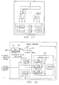
- Figure 1 illustrates a general block diagram of an optical switched network 4.
- the optical switched network 4 includes multiple electronic ingress edge routers 6 and multiple egress edge routers 8.
- the ingress edge routers 6 and egress edge routers 8 are coupled to multiple core routers 10.
- the connections between ingress edge routers 6, egress edge routers 8 and core routers 10 are made using optical links 12.
- Each optical fiber can carry multiple channels of optical data.
- a data burst (or simply "burst") of optical data is the basic data block to be transferred through the network 4.
- Ingress edge routers and egress edge routers are responsible for burst assembly and disassembly functions, and serve as legacy interfaces between the optical switched network 4 and conventional electronic routers.
- a burst 28 will not be terminated electronically when it is transmitted across a hop within network 4. It will "fly” across the network.
- a companion Burst Header Packet (BHP) 34 is transmitted prior to the departure of a data burst at previous hop.
- the BHP of an optical burst would contain network protocol header such as IP (Internet Protocol).
- IP Internet Protocol
- the BHP of an optical burst would contain network protocol header such as IP (Internet Protocol).
- IP Internet Protocol
- IP Internet Protocol
- the coupled optical data burst such as when it will arrive, in which channel it would arrive, and what is its length. This is to describe the temporal and spatial position of the associated optical burst relative to the temporal and spatial position of the BHP itself.
- this invention assumes that both optical data bursts 28-and BHPs 32 are transmitted in synchronous fixed length slots 30.
- a slot 30 used to transmit an optical burst is referred to as a data slot 29. At least one data slot will be needed to transmit a burst.
- the consecutive sequence of data slots (at least one) that are used to transmit one burst is referred as a Slot Session (SS).
- control slots 31 that are used to transmit BHPs and other network Control Packets (CPs) are called control slots 31.
- CPs network Control Packets
- a control slot 31 is divided into Micro-slots 34.
- One BHP 32 uses one micro-slot 34.
- One CP would use at least one micro-slot.
- the consecutive sequence of micro-slots that are used to transmit a CP is referred as a Micro-Slot Session (MSS).
- MSS Micro-Slot Session
- BHPs are transmitted as In-Band or as Out-Band.
- BHPs are always transported in the same DWDM (Dense Wavelength Division Multiplexing) channel as its associated burst is (see Figure 32).
- BHPs are transmitted in a separate control channel that may provide BHPs transportation for a group of DWDM channels.
- Figure 4 is a general block diagram of a burst switching based optical core router 10 using Out-Band BHP transmission.
- Optical fibers 12 carrying one or more channel groups 26 (incoming) or 27 (outgoing), with each channel group 26 or 27 including a control channel 17 (incoming) or 18 (outgoing) and a group of multiplexed data channels 16 (incoming) or 21 (outgoing).
- Incoming channel groups 26 are received by the ingress of I/O cards 14.
- the ingress of I/O cards 14 separate the incoming data channels 16 and the incoming control channel 17 of the incoming channel group 26. It then sends the separated channels to switch 19.
- the incoming control channel 17 is sent to the electronic control 20 of switch 19 and the incoming data channels 16 are sent to optical switch 22 of switch 19.
- the electronic control 20 responsive to information from the incoming control channels 17, controls the path of bursts from on the incoming data channels 16 to a desired outgoing data channel 21.
- an outgoing control channel 18 and outgoing data channels 21 of an outgoing channel group 27 are sent to an egress of an I/O card 24, and be united and sent out through fiber 12.
- Figure 5 illustrates transmission of data slots 29 and control slots 31 in a fiber 12 when BHPs are transmitted as Out-Band.
- DWDM channels in a fiber 12 are grouped together as channel groups 26 or 27.
- a channel group 26 or 27 includes one control channel 17 or 18 and a number of data channels 16 or 21.
- Each data channel carries data slots 29 that transmit bursts 28 by slot session.
- Each control channel carries control slots 31 that use micro-slots 34 to transmit BHPs 32 and CPs.
- the number of micro-slots 34 within a control slot 31 will be a deterministic factor for burst arrival rate, since no burst 28 can arrive without an earlier-arriving BHP 34.
- the channel slot rate is R slot
- the number of data channels 16 or 21 in a channel group 26 or 27 is N
- the number of micro-slot in one slot is ⁇ , then there must be: ⁇ R slot-c ⁇ R slot - d 1 + R slot - d 2 +...+ R slot - dN BL
- T n + refers to a time after and near T n
- T n - refers to a time preceding and near T n
- the "T n slot" refers to the time duration from T n + to T n+1 -.
- Data bursts 28 of optical information are received at the inputs of optical switch 22.
- the BHP which contains the information defining the desired routing of it associated burst, is converted to electronic form.
- the information in the BHP is used by the electronic control 20 to configure the optical switch 22 prior to the arrival of the data burst 28.
- the optical matrix 22 is already configured to switch the burst 28 to the proper desired outgoing data channel 21 or to fiber delay line as described in greater detail below. Accordingly, the bursts 28 can be switched through router 10 without conversion of the burst data into electrical form.
- the BHPs 32 are converted back into optical form and reunited with their associated data burst 28 in the egress of I/O card 24. The BHP 32 must continue ahead of the burst 28 in order for switching to occur in the optical domain.
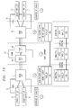
- FIG. 6 illustrates a more detailed block diagram of the optical switch 22.
- Optical switch 22 includes optical matrix 40, having input ports 42 and output ports 44.
- One or more fiber delay lines (FDLs) 46 are coupled between certain input ports and output ports, and there are multiple possible delay values.
- This invention assumes that the basic delay value ⁇ is the same as one slot 30 duration, and a delay value of a FDL is always an integral numbers of the basic delay ⁇ .
- Multiple delay lines 46 may be assigned to some delay values. For example, there may be five 1 ⁇ delay lines and five 2 ⁇ delay lines.
- the remainder of the input ports 42 and output ports 44 are coupled to individual data channels from fibers 12.
- the electronic control 20 sets the paths (from an input port 42 to an output port 44) through the optical matrix 40.
- Each incoming data channel 16 is coupled to an input port 42 and each outgoing data channel 21 is coupled to an output port 44.
- an incoming data burst 28 may be switched to any available output port 44.
- the associated BHP 32 will indicate a specific output channel group 27 as the destination.
- the electronic control 20 will find an available output data channel on the outgoing channel group 27 and direct the data burst 28 to that data channel.
- the optical matrix 40 switches the corresponding input port 42 to the output port 44 of the desired outgoing data channel 21.
- the optical data can be delayed for a short period of time without any conversion to the electrical domain.
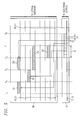
- FIG. 7 illustrates a more specific block diagram of the electronic control circuitry 20.
- the electronic control circuitry 20 includes ingress processors 50 for each incoming control channel 17, egress schedulers 52 for each outgoing control channel 18 and an electronic matrix 54 for connecting any ingress processor 50 to any egress processor 52.
- a BHP 32 arrives on an incoming control channel 17, it is processed by the electronic control circuitry 20.
- the ingress processing 50 and the electronic matrix 54 of the electronic control circuitry 20 handle the traditional packet forwarding and routing functions of a router. Accordingly, the ingress functions convert the optical BHPs 32 into electrical BHPs 32.
- Each BHP contains the destination information that defines the desired output channel group 27 for the associated packet. Based on this information, the BHP is routed through the electronic matrix to the correct egress scheduler 54.
- An egress scheduler 52 handles the requests of the BHPs that have been forwarded to it, as described in greater detail below. For purpose of this specification, a slotted scheduling method is presented.
- Figure 8 illustrates a timing diagram showing minimum A min and maximum A max arrival time of bursts 28 relative to their BHPs 32.
- a min and A max are both described in terms of slots.
- the values of A min and A max are depending upon system design factors such as burst loss rate, burst delay and so on.
- Figure 9 illustrates how burst loads for a channel are modeled. In the illustrated embodiment, the burst load for each data channel of an output fiber is modeled based on A min , A max , and delays attributable to the fiber delay lines (FDLs) 46.
- FDLs fiber delay lines
- the basic fiber delay line unit ⁇ which is the same as a slot time period, and the delaying time units of the cascaded output of a fiber delay line will be always an integer number k times the basic unit ⁇ .
- the maximum possible delay through a fiber delay line 46 is denoted as D max .
- a vector dlt ( D 0 , D 1 , D 2 , ... , D k ) denotes the possible delay values, where D 0 is defined as no delay and D k means a k slot duration delay.
- D k means a k slot duration delay.
- D k there may be multiple delay lines.
- the number (m) of delay lines can be different for each delay value D k .
- the number of entries to FDL is normally not equal to the number of input or output channels. In Figure 4, there are N channels, and m fiber delay lines 46.
- burst switching traffic will be distributed to output channels by bursts 28, which may occupy multiple slots 30.
- a burst 28 has variable number of slots, and various arrival times relative to its BHP 32. Therefore, the distribution of bursts to output channels becomes a problem, since the availability of both an output channel on the desired output fiber and a fiber delay line 46 becomes dependent upon previous transmitted bursts.
- a discrete time model for the burst load up to the maximum delay of a channel is provided.
- time window is defined, referred to herein as the Slot Sequence Window (SSW), shown in Figure 9.
- SSW contains a fix length sequence of discrete time points T 0 , T 1 , ... , T m .
- T i-1 is called its predecessor
- T i+1 is called its successor.
- the start of the sequence T 0 also called S point
- the end of the sequence T m also called M point, has no successor.
- the S point is defined as the time at which the BHP 32 of a burst 28 arrives at the traffic scheduler 52 of an outgoing channel group 27 .
- the A max point ( Figure 8) is the maximum time offset from S point for the burst arrival time at the optical matrix 40.
- the A min point defines the minimum time offset from S point for the burst arrival time at the optical matrix 40.
- the M point is the maximum delay (D max ) from the A max point for the burst that can be provided by a fiber delay line 46, once the burst 28 has reached the optical matrix 40.
- a burst brst has "arrived” at point T i if at T i - it may have not arrived, but at T i + it would have arrived.
- a burst brst has "left” point T i if at T i - it may still be with the system, but at T i + it would have left.
- a time point T i has been "occupied” if the period from T i + to T i+1 - has been assigned to an incoming burst, otherwise the time point is "empty".
- An E-list denotes that which time point of SSW is empty, and which has been occupied.
- the M point has one more variable denoted as the "M-counter".
- the M-counter is used in cases where the M point is occupied; it counts the number of slots cycles before M point becomes empty again. In other words, the M-counter counts the number of slots of a burst 28 that lie outside of the SSW.
- SSW Since all the time points in SSW are relative to the S point, and the S point is a BHP's arrival time, properties defined in SSW are BHP arrival time specific. Therefore, even if two bursts arrive at the same time, as long as their BHPs arrive at different times, they see different SSW windows. Similarly, if two bursts arrive at different times, as long as their BHPs arrive at the same time, they have the same SSW windows.
- the effects of all the previous bursts' transmission can be counted by shifting the E-list .
- the E-list will be right-shifted as it is shown in Figure 10.
- the S point E value of the previous SSW will no longer be counted by the scheduler.
- the M point E value of current SSW will be determined by value of M-counter . If the M-counter does not equal to 0, the E value of the M point of current SSW will be set as 0, and M-counter will be decreased by 1. If M-counter does equal to 0, then E value of M point will be set as 1.
- Expression (2) and (3) have demonstrated the generality of the traffic model.
- Variable ⁇ in expression (2) represents a viewpoint of interest
- ⁇ represents the basic unit duration for data slots, control slots and delay lines.
- the length of the E-list represents the operation window of the scheduler, which is defined by maximum time offset and maximum delay value.
- Expression (2) shows that the loading condition of a channel within the operation window can be exactly described
- expression (3) shows that the connection of such windows in consecutive time sequence. Therefore, the traffic condition of a channel can be accurately described.
- This model relies on only assumptions of synchronous transmission of data 29 and control 31 slots 30, and different integral numbers of the slot-duration-delay-lines 46. Specially, it is independent of the transmission frame of data and control slots.
- the shifting process can take account of all the effects of previous burst transmission, but it is independent from the process of allocating the A point (arrival point) of an incoming burst. Accordingly, the receiving process at the ingress of the optical matrix 40 can be separated from the receiving process at the ingress of the electronic matrix 54. This can provide flexibility in system configuration of the synchronization process.
- bursts there are three bursts to be scheduled in Figure 11: BL 1 , BL 2 , and BL 3 .
- the associated BHPs 32 arrive at different times.
- Burst BL 1 is three slots in length and its BHP arrives between ⁇ 0 and ⁇ 1 .
- Burst BL 2 is four slots in length and its BHP arrives between ⁇ 1 and ⁇ 2 .
- Burst BL 3 is two slots in length and its BHP arrives between ⁇ 2 and ⁇ 3 .
- FDLs 46 in the system; they can delay two, four or six slot time periods respectively.
- T 3 corresponds to the maximum arrival time of bursts relative to S point T 0 .
- T 5 , T 7 , and T 9 correspond to the exits of the fiber delay lines 46 relative to T 3 . They represent two, four, and six slot period delays respectively.
- T 9 is the M point; its M-counter is 0. Any time beyond T 9 is neither controlled nor managed. It should be noted that the FDL exit points are relative to its entry.
- T 2 denotes the arrival time of BL 1 relative to the S point.
- T 4 , T 6 and T 8 denote the FDL exits relative to burst arrival time T 2 . Since all the points are empty, there is no need to delay the incoming burst. After the scheduling, T 2 , T 3 , and T 4 are occupied.
- T 0 ⁇ 2
- T 4 , T 6 and T 8 denote the FDL exits relative to burst arrival time T 2.
- T 2 , T 3 are occupied, BL 2 will be delayed.
- the first consideration is whether there is a gap in the SSW that can accommodate the burst from the exit of the FDL.
- the second consideration is whether there is an FDL entry available. In Figure 9, it is assumed that there is no entry available for the 2-slot-time FDL.
- BL 2 when BL 2 is scheduled to be sent out at T 6 , its span will excess the SSW window.
- T 0 ⁇ 3
- the previous SSW would be right shifted again, and BL 3 will be scheduled based on the shifted SSW.
- T 3 denotes the arrival time of BL 3 relative to the S point.
- T 5 , T 7 and T 9 denote the FDL exits relative to burst arrival time T 3 . Since T 3 and T 4 are not occupied, burst 3 can be scheduled as in Figure 9.
- this procedure does not guarantee the order of the bursts.
- BL 2 and its BHP arrive earlier than BL 3
- BL 3 sets out earlier from this node.
- Figure 12 and Figure 13 illustrate the modeling of FDLs 46 and the BHP micro-slots 34.
- the availability of either a FDL 46 or BHP micro-slot 34 can be a bottleneck for scheduling a burst.
- With concept of SSW models for both FDLs 46 and the BHP micro-slots 34 can be easily created.
- each fiber delay line 46 can be modeled over a window inside SSW.
- Figure 12 illustrates a model for a delay of D k ⁇ dlt with m entries. For purpose of supporting SSW based scheduling, for every D k , it is necessary to know at every possible burst arrival time, whether there are entries available, and how long the gap is. Notice that this is needed because each FDL 46 is shared among channels. If an FDL 46 is used by one channel only, the SSW should be able to represent the status of its FDL 46.
- FIG. 12 For every entry E k of a FDL D j , there is an FDL Entry Status Window (FESW) associated with it.
- Figure 12 shows m entries (f 1 through f m ) for delay D k . Every FESW starts from the S point, and ends at the A max point, i.e., T 0 , T 1 , ..., T Amax .
- a variable O is associated with every time point T i of the window. If T i .O x is equal to 1, means that the f x (where x is between 1 and m) entry of FDL D k is empty at T i . Otherwise, if T i .O x is equal to 0, means that the f x entry of FDL D k is occupied at T i .
- the O values of the FESW for entry f x will be set to "0" from T i to T i+BL-1 . If T i+BL-1 spans beyond T Amax , the A max- counter will be used; hence, O m will be set to "0" from T i to T Amax and the A max -counter will be set to i +BL-1-A max .
- FESW will right shift once every slot cycle.
- the A max -counter records the number of slot cycles before T Amax. f be set to 1. Use of A max -counter is like the use of M-counter in SSW windows.
- FIG. 13 illustrates a Micro-Slot Status Window (MSSW).
- MSSW Micro-Slot Status Window
- the MSSW starts from S point, and ends at L point.
- the L point is set to the M point, minus the minimum time offset between a data burst and its BHP.
- the MSSW records the status of control channel egress. From a scheduling point of view, for every slot time point from S to L , the egress scheduler 52 needs to know if there are micro-slots 34 available. A micro-slot 34 can be used to transmit BHPs as well as CPs. This can be achieved easily using the same mechanism as used to model FDLs' availability. Assuming that there is a time sequence T 0 , T 1 , ...,T L for every MSSW, a variable m ik can be associated with every time point T i of the window, specifying the availability of the associated time slot. If T i. m ik is equal to 1, the micro-slot Mslt k of T i is occupied. Otherwise, if T i .m ik is equal to 0, the Mslt k micro-slot of T i is available. As with the SSW and FESW , the value of m will be right shifted once every slot cycle.
- m j 0 if m j equals to 0, means that there is at least one micro-slot available in slot T j , otherwise it means that all the micro-slots of the slot T j have been used.
- a traffic model for slotted burst over a switched optical channel. It is developed based on a basic fact that an FDL buffer capable optical switch could only monitor and manage a limited time window, and all the consequence of previous burst transmission can be counted by right shifting the window. With this model, burst transmission requests can be scheduled efficiently.
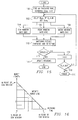
- Figure 14 shows timing relations between the windows in the model.
- the Slot Sequence Window (SSW) is defined on channel basis, the Micro-Slot Status Window (MSSW) and FDL Entry Status Window (FESW) are shared among the channels.
- MSSW is on micro-slot basis, while FESW is per entry point and per FDL.
- All windows will be right shifted once per slot cycle. The right most value of previous slot will become past, and will not be used for any more. The left most value of the new window will be determined through recorded variables. M-counter and A max -counter are defined for this purpose.
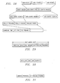
- the slotted burst scheduling process can be implemented as shown in Figure 15.
- the basic idea is that by the time a BHP arrives, the system will convert the burst description in BHP (burst arrival time, burst length) into a bit sequence representation, referred to herein as Bseq.
- Bseq tells the system in terms of SSW when the burst would arrive, and the bursts length. If the Bseq expands over the M point of SSW, the rest of it will be recorded in a variable called B-counter .
- Bseq A very important technical feature of this invention is that by adjusting the Bseq. representation of burst arriving time and the B-counter , Bseq patterns would be able to take account the effects of different delays D k s. Based on this, the scheduling method can consider a specific delay choice once per processing cycle, as described below, until a match been found.
- the processes for finding a match with SSW, FESW and MSSW are independent, and they can be implemented by combinatory circuit and can be executed in parallel.
- step 100 when a Burst Header Packet (BHP) arrives, it holds a definition of the incoming burst: when it will arrive, and how many slots it has. This information is converted into a bit sequence representation Bseq, and then use this bit representation to find out a suitable gap within the SSWs , together with the conditions in FESW window and MSSW window.
- BHP Burst Header Packet
- the Bseq representation of a burst is defined the same as the E-list over SSW window. Only in this case, "1" represents that a slot time point is needed by a burst, and "0" to represent that the point is not needed.
- B-counter For worst-case scenarios in Figure 15, for one incoming burst, k bit representations are generated, namely, Bseq 0 , Bseq 1 ,..., Bseq k .
- B-counter For a burst that spans over the SSW window, a variable called B-counter records the bits that are outside the SSW.
- the number of all possible bit representations is definite. It is decided by the size of the SSW window. As it is shown in Figure 16, there are finite numbers of possible combinations of the incoming time slot point and its length within the SSW window. If a burst has slots coming after the M point, it will be regarded as an "infinite burst". For an infinite burst, the slot length after the M point will be represented by the variable called B-counter . An infinite burst will occupy M point until B-counter becomes 0. An infinite burst can match with a SSW if and only if the SSW's M -point is not occupied.
- all the possible bit representations of incoming bursts are saved, then retrieved when a burst comes using (start time, length) definition inside the BHP.
- the space complexity of this method is determined by size of SSW window. If the size of SSW is S ssw , then the number of stored patterns is (S ssw ) 2 / 2 .
- step 102 Bseq is delayed by D i .
- D i 0 (i.e., no delay).
- Simultaneous matching with the SSW, FESW and MSSW is performed in steps 104,106 and 108, respectively.
- step 104 the matching is performed in the SSW.
- the number of SSW windows is equal to the number of data channels.
- the number of SSW windows is equal to the number of data channels. Therefore, there is a selection process for every Bseq i , since there might be more than one such match.
- the selection process should choose the gap that fits the burst best, and leave the more space the possible.
- the match operation for every SSW can be done in parallel.
- step 106 the matching is performed in the FESW.
- the same principle of step 104 applies to the match operation for FESW.
- the number of FESW is comparatively larger. If there are k levels of delays, and M entries for each delay, then there are k ⁇ M FESW windows. But for a processing cycle of the scheduling process, since every cycle only tries to match with one possible delay, the search space is M . They also can be done in parallel.
- step 108 matching is performed in the MSSW.
- the search process for micro-slot is fairly simple. Once a Bseq i is given, the burst departure time is also defined, so by using the maximum and minimum time offset, the searching area of the MSSW windows is known. With the model of MSSW like in Figure 13, a deterministic result can soon be found.
- step 110 the matching results are checked and, if the burst can be scheduled using a delay D i (step 112), the MSSW, FESW and SSW windows are updated in step 114. Otherwise, if a scheduling cannot occur in step 110, the delay D i is incremented in step 116. If the delay D i is within the delay range in step 116, the sequence of steps 102-110 is repeated with the new D i and Bseq i ; else, the burst is dropped in step 118, because it cannot be scheduled at any available delay.
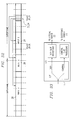
- FIG 18 illustrates a block diagram of an egress scheduler 52.
- the BHP 32 is received by a Bseq generation circuit 130, which generates a Bseq based on the length and time of arrival information of the BHP, as described above.
- a shift circuit 132 shifts the Bseq according to the current delay (step 102 of Figure 13).
- the shifted Bseq is input to a matching circuit 134.
- the matching circuit 134 performs three matches in parallel.
- the SSW matching circuit 136 determines whether the current Bseq can fit in one of the SSW (there is one SSW for each data channel in the data channel group associated with the egress scheduler 52).
- the FESW matching circuit 138 determines whether a delay line with the current delay will be available when the burst arrives.
- the FESW information (there is one FESW for each entry into each delay) is available to all egress schedulers 52.
- the MSSW matching circuit 140 determines whether there is an available micro-slot 34 in the control channel associated with the egress scheduler 52.
- the MSSW information is specific to the associated egress scheduler 52.
- the matching circuit 134 If there is a match in the matching circuit 134, i.e., if all three matching circuits 136, 138 and 140 match, information from the SSWs is sent to the Optical Matrix to control the path of the bursts.
- the information includes incoming burst channel ID, incoming slot ID, outgoing channel ID and outgoing slot ID and E value. If no match is found, another Bseq bit pattern of different delay is generated to attempt another match for a different delay time.
- Figure 19 through Figure 31 illustrate a protocol architecture that may be used in conjunction with the optical burst network 4 described herein.
- packets outside of the optical burst switched network are received at ingress routers 6; information in the packets are converted to bursts 28, which propagate through the optical burst switched network 4.
- the bursts are converted back into packets.
- the protocol described herein provides format for representing information as it propagates through the optical burst switched network 4.
- each burst 28 is transmitted over one or more slots. Further, the BHPs 32 for various bursts 28 are transmitted within micro-slots 34 within a control slot 31.
- the protocol architecture describes a method of transmitting both bursts 28 through slot session and BHPs 32 and CPs through micro-slots. The scenarios of packets processing are described as in Figure 19.
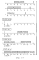
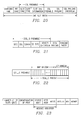
- Figure 20 illustrates a diagram of a slot of information in a common slot format.
- the common slot format (or Common Slot Layer, CSL) is designed for both data (bursts) and control (BHP) slots.
- the common slot layer has six parts: Guarding time and bit sync; CSL preamble; SSSL (Service Specific Slot Layer) preamble, Slot Payload and Slot check sum. These fields are described in Table 1.
- Common Slot Layer Fields Guard time The guard time is used as an edge to trigger the optical matrix synchronizers. The guard time has a maximum length. If the needed guarding time is less than the maximum length, it can be filled by bit sync.
- Bit synchronization pattern is necessarily to extract clock synch information at the transceiver. This pattern starts immediately after the guard time. In the preferred embodiment, bit synchronization pattern is minimum of 128 bits.
- CSL preamble The overhead information common for both data and control slot. It is also called the header of Common Slot Layer (CSL).
- SSSL preamble SSSL Preamble is the header of Service Specific Slot Layer (SSSL).
- the SSSL layer can be one of two types: the SSSL_D for a data channel and the SSSL_C for a control channel. Their header information is different SSSL Payload In a data slot, SSSL payload carries the data burst traffic. In control slot, the SSSL payload carries the Burst Head Packets (BHPs) and other network control and management messages (CPs).
- BHPs Burst Head Packets
- CPs network control and management messages
- the CSL preamble contains three fields. These are described in Table 2.
- Common Slot Layer Preamble Fields Slot Sync Slot sync is used for slot boundary recognition Slot Type Slot type field indicates the type of a slot. Four types of slots have been identified, they are data slot, control slot, idle slot and OAM (operation, administration and maintenance) slot. Idle slots are sent out when there is no data to send.
- OAM slots are used by optical transceiver for transmission OAM functions only.
- OAM address OAM address refers to the transceiver where the loop back slot is going to be terminated.
- the SSSL Preamble varies depending on whether the information in the SSSL Payload is either data or control information. If the information is data, a SSSL_D Preamble is used; if the information is control information, a SSSL_C Preamble is used.
- Figure 21 illustrates a SSSL_D for data information.
- the fields of the SSSL_D are shown in Table 3.
- SSSL_D Preamble Fields Slot Session ID identifies the slots that transmit the same data package. Within the optical burst network, a slot session is used to transmit a data burst. The SSID would be the same as Burst ID.
- Slot Session Length Specifies the length of the slot session in number of slots.
- Slot Sequence Number It indicates the slot sequence number in the session.
- the initial sequence number is set as the total length of the session, then decrease to 1.
- Slot Session Type Indicates slot type for quality of service purposes. Header Check Sum A check sum used for SSSL headers.
- control channel 18 is responsible for transmitting BHPs and CPs.
- CP packets may include LCP (Link Control Protocol), IPCP (Internet Protocol Control Protocol), MPLSCP (Multi-Protocol Label Switching Control Protocol) and ICMPv4 (Internet protocol Control Message Protocol), and so on.
- LCP Link Control Protocol
- IPCP Internet Protocol Control Protocol
- MPLSCP Multi-Protocol Label Switching Control Protocol
- ICMPv4 Internet protocol Control Message Protocol
- SSSL_C Control-channel Service Specific Slot Layer
- Figure 22 illustrate a diagram of a SSSL_C format.
- the SSSL_C payload is divided into micro-slots, and is partitioned into a CP window part and a BHP window part.
- the CP window part is allocated for transmitting network control information (CPs) and the BHP window part is used to transmit BHPs.
- CPs network control information
- the difference is that for every BHP, the micro-slot contains a complete IPV4/PPP encapsulation (PPP stands for Point to Point Protocol).
- PPP Point to Point Protocol
- the respective windows can change size if necessary for optimal transfer of the control information. It is assumed that a change in the partition between the CP and BHP windows would happen after or before a completion of a CP packet so that there in no change of the CP window size while a CP packet is in transmitting.
- the CP window and BHP window size can also be statically set by management configuration functions.
- the CP window assumes to carry all network control information other than BHPs, including possible control messages in layer 2 like LCP (Link Control Protocol) messages for IPV4 (IPCP: Internet Protocol Control Protocol) and MPLS (MPLSCP: Multi-Protocol Label Switching Control Protocol).
- LCP Link Control Protocol
- IPCP Internet Protocol Control Protocol
- MPLS MPLSCP: Multi-Protocol Label Switching Control Protocol
- SSSL_C Preamble Fields Number of CP micro-slots Assuming that the CP window always start from 0 micro-slot, this field defines the number of micro-slots (#cp) that are used for transmitting CP messages.
- the CP window would be equal to #cp
- the BHP window would be equal to number of micro slots minus #cp (#number of micro-slots - #cp).
- Type of micro slots and protocol encapsulation Specifies types micro slots, and possible encapsulation of protocols. It also needs to distinguish if IPV4/PPP/HDLC or IPV4/MPLS/PPP/HDLC encapsulation is used.
- Source address, destination address and Micro-Slot Session ID are used to uniquely identify the CPs within the optical burst network.
- Source address and destination address are IPV4 addresses.
- MSSID is an integer managed by the source node.
- Micro-Slot Session ID identifies the slots that transmit the same CP between the source and destination.
- Micro-slot Session Length MSL
- MSL Micro-slot Session Length
- MSSNUM Micro-slot Session Sequence NUMber
- Micro-slot Map (msmap) Indicates which micro-slot is not used in the control slot. The number of bits in this field equals exactly the number of micro slots of a control slot. Value 1 represents used, 0 represents empty.
- BHP and CP The transmission of BHP and CP is shown as in Figure 24.
- a CP packet will occupies slots in the control channel.
- a BHP will use one of the micro-slot in the BHP window of the slot.
- each BHP and associated information is contained in a micro-slot with the BHP window; a CP and associated information may be split between CP windows of a sequence of slots.
- FIGs 25 through 28 illustrate transmission of a burst 28.
- the overall structure is shown in Figure 28.
- a burst header (Figure 25 and as described in Table 5) is first added to the burst 28.
- the entire burst is divided into segments.
- the segments then are attached to the SSSL preamble, and are transmitted by the slots.
- Burst Layer Fields Burst ID Burst ID is a number. It should be unique per network edge. Burst ID is also present in BHP.
- the Slot Session ID (SSID) of SSSL will be set as the Burst ID.
- Burst Type Burst types may be distinguished for quality of service requirements at the network edge.
- Burst length length of Burst Id field + length of Burst type field + length of Burst length filed + length of number of sub- packet filed + length of sub-packet 1 + ... + length of subpacket k Number of subpackets It indicates the number of sub-packets
- Figure 25 through Figure 28 are related to processing of burst segmentation and assembly, error detection and flow control.
- a data burst is composed of many network layer packets.
- PPP protocol is employed to support transportation of network packets over the data channel.
- bit stuffing it is preferable to not use bit stuffing, because this would require allocating space for the worst-case bit stuffing scenario, which could be awkward for variable length IP packets, especially since many of them may be cascaded together to form the super packet. Therefore, length indicator framing is chosen as a preferred method for layer 2 framer.
- Figure 27 show the organization of a super-packet.
- incoming IP packets or other data format
- a PPP header and packet length indicator are added to the packets to form a sub-packet, shown in Figure 26.
- the super-packet is formed by accumulating all sub-packets associated with a burst and adding a burst preamble (shown in detail in Figure 28).
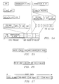
- BHP/CP encapsulation is shown in connection with Figure 29 to Figure 31. Both BHP and CPs are transmitted in the control slots that are treated as a PPP link. The encapsulation of BHP and CP are different, as described below.
- a BHP is a fixed length packet. It should always occupy one micro-slot of SSSL_C. Therefore no length indicator is necessary.
- the fields for a BHP are provided in Tables 6 and 7.
- BHP IPV4/MPLS/PPP Encapsulation Protocol Field (PPP header field) This is a two octet field, and its value identifies the payload encapsulated in the Information field of the packet. The structure of this field should be consistent with the ISO 3309 extension mechanism for address fields.
- MPLS Field Contains the MPLS label as defined by IETF MPLS working group IPV4 Header It is a standard IPV4 header except that all the options will not be used. To support BHP, the PROTOCOL field of IPV4 header may be extended.
- BHP Payload is shown in Figure 30 and described in Table 7. All the BHPs will be transported in a micro-slot by using IP/MPLS/PPP encapsulation as shown in Figure 29.
- IDCG Ingress Data Channel Group ID
- IDDC Ingress Data Channel
- BID Burst ID
- the burst ID is a sequence number that is unique per edge. The BID is present in both the BHP and data burst, can be used for correlation purposes.
- Burst DURation (BDUR) The number of slots before the corresponding burst would arrive.
- Burst time offset (BOFFSET) Indicates burst offset in terms of how many slots before the burst arrives the optical matrix
- Control packets may be of variable length.
- the length of a CP is indicated by the length field.
- the protocol field indicates the protocol type of the CP.
- the CP Payload carries the CP information.
- the padding field includes unused bits.
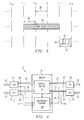
- Figure 32 illustrates a timing diagram showing in-band transmission of control and data bursts on a single channel.
- An in-band implementation uses the same basic control/data structure as described above; however, slots 31 of BHPs 32 are transmitted on a common channel with the associated data bursts 28.
- slots 30 are grouped into superframes.
- Control slots 31 and data slots 29 may be arbitrarily assigned within a superframe.
- the control slots 31 could be placed are regular positions within a superframe.
- Bursts 28 may span multiple superframes. Multiple control slots 31 may be present within a single superframe.
- a control slot 31 is divided into multiple microslots 34.
- Each microslot 34 may store a BHP 32 (or a control packet).
- Each BHP 32 is associated with a burst 28 on the same channel, so long as the timing relationship of the burst and its associated BHP is between A min and A max .
- control and data are transmitted together.
- FIG. 33 illustrates a I/O port 14 for use with in-band transmission.
- I/O port 14 includes interface 150, data slot processor 152 and control slot processor 154.
- Interface 150 separates the data in control slots 31 from data slots 29. Identification of control slots 31 could be accomplished, for example, by a unique synchronization pattern.
- the data is transferred to the control slot processor 154 for preparing the data for transmission to the electronic control circuit 20.
- data slots 29 are sent to data slot processor 152 for preparation for entering the optical switch 22.
- the protocol described above can be used for either in-band or out-band transmission modes.
Applications Claiming Priority (16)
| Application Number | Priority Date | Filing Date | Title |
|---|---|---|---|
| US795374 | 1991-11-21 | ||
| US795373 | 1991-11-21 | ||
| US257885 | 1994-06-10 | ||
| US25788500P | 2000-12-22 | 2000-12-22 | |
| US25742900P | 2000-12-22 | 2000-12-22 | |
| US25782500P | 2000-12-22 | 2000-12-22 | |
| US25763900P | 2000-12-22 | 2000-12-22 | |
| US257825 | 2000-12-22 | ||
| US257639 | 2000-12-22 | ||
| US257429 | 2000-12-22 | ||
| US79538201A | 2001-02-26 | 2001-02-26 | |
| US795382 | 2001-02-26 | ||
| US09/795,373 US6963564B1 (en) | 2000-12-22 | 2001-02-26 | Method and apparatus for synchronized slotted optical burst switching |
| US795375 | 2001-02-26 | ||
| US09/795,374 US20020149820A1 (en) | 2000-12-22 | 2001-02-26 | Method and apparatus for transmitting over a slotted OBS network in in-band mode |
| US09/795,375 US20020154360A1 (en) | 2000-12-22 | 2001-02-26 | Discrete time sequence model for slotted and synchronous switching of optical burst signals |
Publications (2)
| Publication Number | Publication Date |
|---|---|
| EP1217862A2 true EP1217862A2 (fr) | 2002-06-26 |
| EP1217862A3 EP1217862A3 (fr) | 2007-08-08 |
Family
ID=27575290
Family Applications (1)
| Application Number | Title | Priority Date | Filing Date |
|---|---|---|---|
| EP01129346A Withdrawn EP1217862A3 (fr) | 2000-12-22 | 2001-12-17 | Procédé et dispositif pour commutation optique dans intervalles synchronisées |
Country Status (1)
| Country | Link |
|---|---|
| EP (1) | EP1217862A3 (fr) |
Cited By (7)
| Publication number | Priority date | Publication date | Assignee | Title |
|---|---|---|---|---|
| EP1588510A2 (fr) * | 2003-01-29 | 2005-10-26 | Telcordia Technologies, Inc. | Commutation par paquets optiques periodiques |
| US7266295B2 (en) | 2003-04-17 | 2007-09-04 | Intel Corporation | Modular reconfigurable multi-server system and method for high-speed networking within photonic burst-switched network |
| US7272310B2 (en) | 2003-06-24 | 2007-09-18 | Intel Corporation | Generic multi-protocol label switching (GMPLS)-based label space architecture for optical switched networks |
| EP1600030B1 (fr) * | 2003-02-28 | 2008-08-20 | Intel Corporation | Procede et systeme de structuration et de formatage de commandes optiques et de rafales de donnees dans des reseaux photoniques commutes par rafales wdm |
| US7734176B2 (en) | 2003-12-22 | 2010-06-08 | Intel Corporation | Hybrid optical burst switching with fixed time slot architecture |
| US8660427B2 (en) | 2002-09-13 | 2014-02-25 | Intel Corporation | Method and apparatus of the architecture and operation of control processing unit in wavelenght-division-multiplexed photonic burst-switched networks |
| WO2016112769A1 (fr) * | 2015-01-16 | 2016-07-21 | Huawei Technologies Co., Ltd. | Procédé et système de retrait d'une tonalité pilote dans un signal optique |
-
2001
- 2001-12-17 EP EP01129346A patent/EP1217862A3/fr not_active Withdrawn
Non-Patent Citations (1)
| Title |
|---|
| YIJUN XIONG ET AL: "Control Architecture in Optical Burst-Switched WDM Networks" IEEE JOURNAL ON SELECTED AREAS IN COMMUNICATIONS, IEEE SERVICE CENTER, PISCATAWAY, US, vol. 18, no. 10, October 2000 (2000-10), XP011055242 ISSN: 0733-8716 * |
Cited By (11)
| Publication number | Priority date | Publication date | Assignee | Title |
|---|---|---|---|---|
| US8660427B2 (en) | 2002-09-13 | 2014-02-25 | Intel Corporation | Method and apparatus of the architecture and operation of control processing unit in wavelenght-division-multiplexed photonic burst-switched networks |
| EP1588510A2 (fr) * | 2003-01-29 | 2005-10-26 | Telcordia Technologies, Inc. | Commutation par paquets optiques periodiques |
| EP1588510A4 (fr) * | 2003-01-29 | 2006-04-12 | Telcordia Tech Inc | Commutation par paquets optiques periodiques |
| EP1600030B1 (fr) * | 2003-02-28 | 2008-08-20 | Intel Corporation | Procede et systeme de structuration et de formatage de commandes optiques et de rafales de donnees dans des reseaux photoniques commutes par rafales wdm |
| US7848649B2 (en) | 2003-02-28 | 2010-12-07 | Intel Corporation | Method and system to frame and format optical control and data bursts in WDM-based photonic burst switched networks |
| US7266295B2 (en) | 2003-04-17 | 2007-09-04 | Intel Corporation | Modular reconfigurable multi-server system and method for high-speed networking within photonic burst-switched network |
| US7272310B2 (en) | 2003-06-24 | 2007-09-18 | Intel Corporation | Generic multi-protocol label switching (GMPLS)-based label space architecture for optical switched networks |
| US7734176B2 (en) | 2003-12-22 | 2010-06-08 | Intel Corporation | Hybrid optical burst switching with fixed time slot architecture |
| WO2016112769A1 (fr) * | 2015-01-16 | 2016-07-21 | Huawei Technologies Co., Ltd. | Procédé et système de retrait d'une tonalité pilote dans un signal optique |
| US9473263B2 (en) | 2015-01-16 | 2016-10-18 | Huawei Technologies Co., Ltd. | Method and system for removing a pilot tone from an optical signal |
| US9705628B2 (en) | 2015-01-16 | 2017-07-11 | Huawei Technologies Co., Ltd. | Method and system for removing a pilot tone from an optical signal |
Also Published As
| Publication number | Publication date |
|---|---|
| EP1217862A3 (fr) | 2007-08-08 |
Similar Documents
| Publication | Publication Date | Title |
|---|---|---|
| US20020154360A1 (en) | Discrete time sequence model for slotted and synchronous switching of optical burst signals | |
| US6963564B1 (en) | Method and apparatus for synchronized slotted optical burst switching | |
| US6898205B1 (en) | Robust transport of IP traffic over wdm using optical burst switching | |
| US6721315B1 (en) | Control architecture in optical burst-switched networks | |
| US5418779A (en) | High-speed switched network architecture | |
| Xiong et al. | Control architecture in optical burst-switched WDM networks | |
| EP1578048B1 (fr) | Transmissions de données commandées par jeton dans des réseaux de transmission | |
| US8406246B2 (en) | Rate-controlled optical burst switching | |
| US20050207755A1 (en) | Scheduling token-controlled data transmissions in communication networks | |
| US20020118420A1 (en) | Method and apparatus for transmitting over a slotted OBS network in in-band mode | |
| US7529267B2 (en) | Data transmissions in communication networks using multiple tokens | |
| US7197051B1 (en) | System and method for efficient packetization of ATM cells transmitted over a packet network | |
| KR20010041442A (ko) | 링 구조의 동적 동기 전송 모드를 동기화하기 위한 장치및 방법 | |
| EP1686734A1 (fr) | Procédé et dispositif pour transmettre un signal optique dans un réseau optique par rafales utilisant le temps d'arrivée | |
| EP1217862A2 (fr) | Procédé et dispositif pour commutation optique dans intervalles synchronisées | |
| RU2294601C1 (ru) | Способ статистического мультиплексирования при передаче информации | |
| JP4546138B2 (ja) | 通信ネットワークにおいてデータのバーストを送信用にスケジューリングする方法 | |
| EP1224833B1 (fr) | Transport efficace de trafic ip via mrl par commutation optique de rafales | |
| KR100467321B1 (ko) | 광 버스트 스위칭 망에서의 스케줄링 방법 및 헤더 패킷 데이터 자료구조 | |
| US7257127B1 (en) | Method and apparatus for burst scheduling | |
| US20020149820A1 (en) | Method and apparatus for transmitting over a slotted OBS network in in-band mode | |
| Farahmand et al. | A layered architecture for supporting optical burst switching | |
| Pradeep | Implementation of optical burst switched IP-over-WDM networks using tunable transmitter and tunable receiver | |
| Ioannis et al. | A survey of Reservation schemes for Optical Burst Switching (OBS) | |
| Peng et al. | Study of hybrid optical burst networks |
Legal Events
| Date | Code | Title | Description |
|---|---|---|---|
| PUAI | Public reference made under article 153(3) epc to a published international application that has entered the european phase |
Free format text: ORIGINAL CODE: 0009012 |
|
| AK | Designated contracting states |
Kind code of ref document: A2 Designated state(s): AT BE CH CY DE DK ES FI FR GB GR IE IT LI LU MC NL PT SE TR |
|
| AX | Request for extension of the european patent |
Free format text: AL;LT;LV;MK;RO;SI |
|
| PUAL | Search report despatched |
Free format text: ORIGINAL CODE: 0009013 |
|
| AK | Designated contracting states |
Kind code of ref document: A3 Designated state(s): AT BE CH CY DE DK ES FI FR GB GR IE IT LI LU MC NL PT SE TR |
|
| AX | Request for extension of the european patent |
Extension state: AL LT LV MK RO SI |
|
| 17P | Request for examination filed |
Effective date: 20080207 |
|
| 17Q | First examination report despatched |
Effective date: 20080304 |
|
| AKX | Designation fees paid |
Designated state(s): AT BE CH CY DE DK ES FI FR GB GR IE IT LI LU MC NL PT SE TR |
|
| STAA | Information on the status of an ep patent application or granted ep patent |
Free format text: STATUS: THE APPLICATION IS DEEMED TO BE WITHDRAWN |
|
| 18D | Application deemed to be withdrawn |
Effective date: 20080916 |