EP1217408A2 - Optical fiber ribbon twisting device and manufacturing system for optical fiber cable components - Google Patents
Optical fiber ribbon twisting device and manufacturing system for optical fiber cable components Download PDFInfo
- Publication number
- EP1217408A2 EP1217408A2 EP01126424A EP01126424A EP1217408A2 EP 1217408 A2 EP1217408 A2 EP 1217408A2 EP 01126424 A EP01126424 A EP 01126424A EP 01126424 A EP01126424 A EP 01126424A EP 1217408 A2 EP1217408 A2 EP 1217408A2
- Authority
- EP
- European Patent Office
- Prior art keywords
- optical fiber
- stack
- closing die
- strander
- production line
- Prior art date
- Legal status (The legal status is an assumption and is not a legal conclusion. Google has not performed a legal analysis and makes no representation as to the accuracy of the status listed.)
- Granted
Links
- 239000013307 optical fiber Substances 0.000 title claims abstract description 45
- 238000004519 manufacturing process Methods 0.000 title claims abstract description 27
- 230000000694 effects Effects 0.000 claims abstract description 4
- 238000000034 method Methods 0.000 abstract description 5
- 239000000463 material Substances 0.000 abstract description 2
- 239000004020 conductor Substances 0.000 description 6
- 239000004519 grease Substances 0.000 description 6
- 230000003287 optical effect Effects 0.000 description 5
- 150000001875 compounds Chemical class 0.000 description 4
- 238000001125 extrusion Methods 0.000 description 3
- 239000000835 fiber Substances 0.000 description 3
- 238000003780 insertion Methods 0.000 description 2
- 230000037431 insertion Effects 0.000 description 2
- 238000012856 packing Methods 0.000 description 2
- 238000005452 bending Methods 0.000 description 1
- 239000011248 coating agent Substances 0.000 description 1
- 238000000576 coating method Methods 0.000 description 1
- 238000007796 conventional method Methods 0.000 description 1
- 239000011159 matrix material Substances 0.000 description 1
- 238000012986 modification Methods 0.000 description 1
- 230000004048 modification Effects 0.000 description 1
- 238000012544 monitoring process Methods 0.000 description 1
- 239000011345 viscous material Substances 0.000 description 1
Images


Classifications
-
- G—PHYSICS
- G02—OPTICS
- G02B—OPTICAL ELEMENTS, SYSTEMS OR APPARATUS
- G02B6/00—Light guides; Structural details of arrangements comprising light guides and other optical elements, e.g. couplings
- G02B6/44—Mechanical structures for providing tensile strength and external protection for fibres, e.g. optical transmission cables
- G02B6/4479—Manufacturing methods of optical cables
- G02B6/449—Twisting
-
- G—PHYSICS
- G02—OPTICS
- G02B—OPTICAL ELEMENTS, SYSTEMS OR APPARATUS
- G02B6/00—Light guides; Structural details of arrangements comprising light guides and other optical elements, e.g. couplings
- G02B6/44—Mechanical structures for providing tensile strength and external protection for fibres, e.g. optical transmission cables
- G02B6/4479—Manufacturing methods of optical cables
- G02B6/448—Ribbon cables
Definitions
- the present invention relates to an optical fiber ribbon twisting device and system for use in the manufacture of fiber optic cables and, more particularly, to a rotatable closing die and a system that uses the same.
- Fiber optic cables include at least one optical fiber that can be disposed in a common matrix coating with other optical fibers defining an optical fiber ribbon.
- Optical fiber ribbons can be formed into a twisted stack for allowing ease of cable bending and maintaining integrity of the ribbon stack.
- Optical fiber ribbon pay-off devices for example stranders, are typically used to define a twisted stack, the twist including a lay length or period of twist.
- a strander typically includes spools of optical fiber ribbons, which spools are commonly termed packages.
- Packages can be mounted to a rotating carriage of the strander.
- optical fiber ribbons are paid off the packages and directed to a pre-wet closing die, as disclosed in United States Patent No. 5,348,586.
- the optical fiber ribbons are collected in a closing die that is shaped to receive the stacked ribbons, which shape is typically that of a generally rectangular orifice. Because the journal is mechanically coupled to the strander, the stack is twisted by rotation as it exits the closing die. The next step can be extrusion of a plastic tube about the twisted stack.
- the stack may be mis-aligned with respect to the tube, variation in ribbon lay length can occur, and monitoring of excess ribbon length may be difficult.
- United States Patent No. 4,765,130 discloses a method and apparatus for making a cable core with cable core units stranded together while drawing the cable core units along a passline through a closing die and while vibrating the closing die. Vibration of the closing die is intended to facilitate movement of insulated conductors of the cable core units over one another to provide a greater and more uniform packing density of conductors in the resulting cable core.
- a typical 3600 pair cable is made by stranding together 36 cable core units, each of which comprises 100 individually twisted pairs of insulated conductors stranded together to form a 100 pair cable core unit.
- the cable core units are passed through a closing die to ensure that the resulting cable core has a uniform diameter and shape.
- Some insulated conductors do not readily slide over one another during the stranding operation and this can limit the minimum size of closing die that can be used. Consequently, the resulting cable core diameter may be larger than is desired. Moreover, because the insulated conductors do not readily slide over one another the packing density of the conductors may be non-uniform.
- the solution involves stranding the cable units along a passline through the closing die, and simultaneously vibrating the closing die to compact the stranded elements together.
- United States Patent No. 4,805,392 incorporated by reference herein, describes manufacture of an optical fiber cable in which optical fibers are paid out from packages and inserted into the grooves of a cable core member by means of an inserting head.
- the core grooves are in the form of an open helix.
- a photoelectric system is disposed between the packages and the inserting head to provide signals indicating the position of the optical fibers advancing from the packages.
- a control device is connected to the photoelectric system and is designed to be responsive to the signals generated therefrom to control the speed at which the optical fibers are paid off from the packages.
- the optical fibers pass through a stationary closing device having holes in a flange fixed on a rigid tubular body through which the grooved core passes.
- An insertion head downstream of the rigid tubular body, inserts the optical fibers into the grooves of the core.
- the foregoing devices and systems address the need for closing devices in cable manufacture, but do not directly address the problems associated with cable components having at least one optical fiber ribbon therein, in particular, optical fiber ribbons formed into a twisted stack prior to extrusion of a tube thereover.
- Stationary dies can contribute to undesirable variations in ribbon lay length.
- a cable component production line comprising:
- Figure 1 is a schematic view of a fiber optic cable production line including a rotatable closing die system according to the present invention.
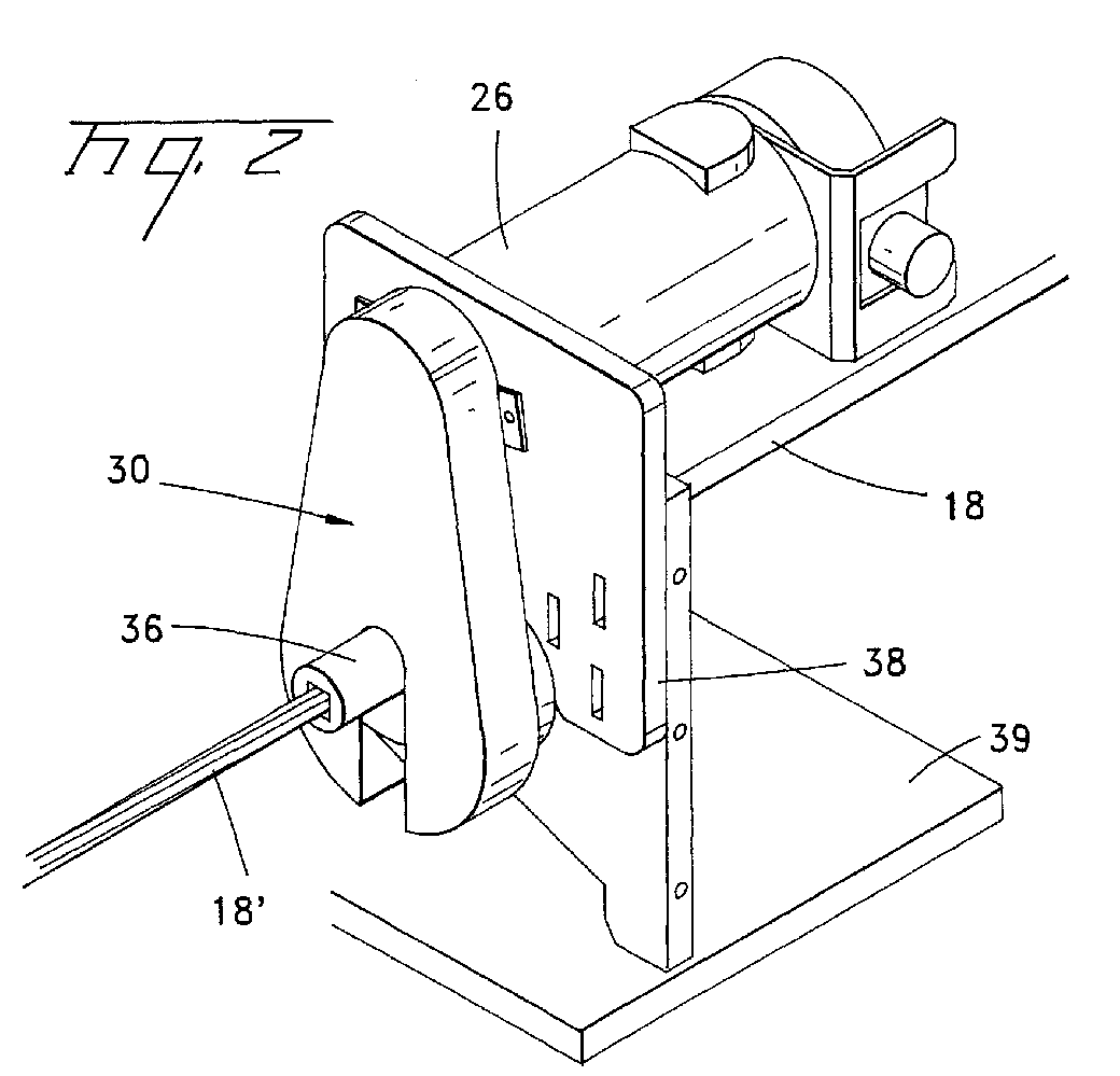
- Figure 2 is an isometric view of a rotatable closing die device according to the present invention.
- Figure 3 is a schematic view of a portion of the closing die device of Figure 2.
- Figure 4 is a schematic view of another embodiment of the present invention.
- Figure 5 is a schematic view of a further embodiment of the present invention.
- production line 10 produces a twisted stack of optical fiber ribbons.
- Production line 10 comprises a production line axis X-X and includes an optical ribbon strander 12, a control system 20, and a rotatable closing die that in the preferred method of use is a rotating closing die 30.
- production line 10 includes a pre-wet closing die 28 and produces a twisted stack of optical fiber ribbons that is fed into a cross-head 40 attached to an extrusion machine (not shown). Within cross-head 40, melt supplied from the extruder is shaped into a plastic tube 46 that is formed about the optical fiber ribbon stack.
- optical ribbon strander 12 includes optical fiber ribbon packages 14 mounted to a rotatable frame 15. Packages 14 pay-off single optical fiber ribbons 16 toward pre-wet closing die 28. Pre-wet closing die 28 is preferably of the type described in United States Patent No. 5,348,586, incorporated by reference herein, for applying a viscous substance to the optical fiber ribbons.
- control system 20 includes, for example, a programmable logic controller (PLC) 22 or a motion controller that interfaces with variable speed motors 24 and 26.
- PLC programmable logic controller
- a preferred function of the PLC or motion controller is based on electronic gearing, that is, the PLC or motion controller to accepts position input from the two motors and generates an appropriate control signal for the closing die motor.
- Motor 24 is mechanically associated with strander 12 for rotationally driving the strander
- motor 26 is mechanically associated with closing die 30 for rotationally driving the closing die.
- Rotating closing die 30 ( Figures 2-3) includes a rotating stack guide 31, preferably not mechanically coupled to the strander, that includes a stack aperture 32 that is profiled to receive a stack of optical fiber ribbons 18.
- the stack aperture is preferably funnel shaped with a smooth finish.
- the stack aperture is preferably of a generally rectangular shape.
- Stack guide 31 includes a drive interface surface 35 that preferably has a surface that can interface with a belt or other suitable device for causing rotation of stack guide 31.
- the stack guide comprises an extension 36 for disposition adjacent to or actually within the cross-head 40 or filling grease area 42 thereof.
- interface surface 35 is operatively associated with a drive member, for example, a drive pulley 33 through a motion connecting member, for example, a drive belt 34.
- belt 34 is a toothed belt, for example, a rectangular profile timing belt.
- Rotating closing die 30 is mounted to a frame 38 that is mounted to an X-Y table 39.
- the frame 38 and X-Y table 39 provide suitable three dimensional adjustability for the rotating closing die.
- rotating closing die 30 is adjustably mounted so that aperture 32 can be properly aligned with line axis X-X. Proper alignment of closing die 30 with cross-head 40 improves the production process in that variations in extruded tube diameter and ribbon lay length are minimized, and stack integrity is preserved.
- control system 20 controls the operation of strander 12 and rotating closing die 30 via motors 24 and 26, respectively.
- Controller 22 is programmed to drive rotating closing die 30 at as close to about a 1:1 rotational ratio with the strander as possible, for example, a 1:0.95 rotational ratio.
- the strander and the closing die rotate at essentially the same speeds, preferably with no change in the ribbon lay length.
- the essentially 1:1 rotational ratio is preferably accomplished by electronic gearing, as a function of the motion controller, with integer gear ratios.
- Encoders respectively associated with rotating devices 12,30 are operative to send electronic pulses to PLC 22, and this input is used to control the speeds of the motors so that an essentially 1:1 rotational ratio exists.
- any error is constantly corrected by the motion controller, thereby avoiding accumulated error.
- the lay length of the twisted ribbon will be preserved after the stack leaves the closing die and as it enters the cross-head.
- ribbon stack 18 exits closing die 30 it is twisted into a suitably twisted ribbon stack 18'.
- twisted ribbon stack 18' is moved into cross head 40.
- cross head 40 includes a filling compound/grease containing area 42 for injecting a filling compound about the stack.
- a plastic tube 46 is extruded about twisted ribbon stack 18 thereby forming a complete optical cable component including optical fiber ribbons, filling compound/grease, and a plastic tube.
- the embodiments of Figures 4 and 5 illustrate the concept of having an extension of the closing die adjacent or most preferably extending into the cross-head. This allows direct insertion of the ribbon stack 18' into the grease flow within or proximate the cross-head.
- extension 36 extends into cross-head 40 or grease containing area 42.
- an extension 36 is formed on a closing die 30 that is mechanically coupled to the strander as a source of rotation.
- Strander 12 is preferably mounted to an adjustable frame for alignment of ribbon stack 18 with the cross-head 40. The adjustability of the closing die avoids mis-alignment of the stack with respect to the extruded tube, variation in ribbon lay length is avoided by the closing die and ribbon strander having an essentially 1:1 rotational ratio.
Landscapes
- Physics & Mathematics (AREA)
- Engineering & Computer Science (AREA)
- Manufacturing & Machinery (AREA)
- General Physics & Mathematics (AREA)
- Optics & Photonics (AREA)
- Ropes Or Cables (AREA)
- Extrusion Moulding Of Plastics Or The Like (AREA)
Abstract
Description
- a rotatable strander for receiving optical fiber ribbon packages thereon, said strander including a closing die coupled to said strander as a source of rotation that at least partially extends into or is proximate a portion of a cross-head containing a grease compound; and
- a controller operatively associated with said strander, said controller being operative to effect rotation of said strander whereby a twist is formed in said optical fiber ribbon stack within or proximate said portion of said cross-head.
- passing an optical fiber ribbon stack through a stack guide independently rotated relative to said strander, and
- forming a twist in said ribbon stack; and
- passing said twisted ribbon stack through a cross-head and extruding a material thereover.
- a stack guide not mechanically coupled to a strander having a ribbon stack aperture therein; and
- a drive member for rotatably driving said stack guide, whereby rotation of said drive member causes said stack guide to rotate and form a twist in said ribbon stack.
The embodiments of Figures 4 and 5 illustrate the concept of having an extension of the closing die adjacent or most preferably extending into the cross-head. This allows direct insertion of the ribbon stack 18' into the grease flow within or proximate the cross-head. In the preferred embodiment (Figure 4)
Claims (10)
- A cable component production line, comprising:a rotatable strander for receiving optical fiber ribbon packages thereon;a rotatable closing die sized to receive an optical fiber ribbon stack; anda controller operatively associated with said strander andsaid closing die for controlling rotation of said closing die, said controller being operative to effect a predetermined rotational ratio between said strander andsaid closing die whereby a twist can be formed in said optical fiber ribbon stack.
- The cable component production line of claim 1, a pre-wet device being interposed between said strander and said closing die.
- The cable component production line of claim 1, said predetermined rotational ratio being about 1:1.
- The cable component production line of claim 1, said closing die being mounted to an adjustable frame.
- The cable component production line of claim 1, said closing die comprising a stack guide.
- The cable component production line of claim 5, said stack guide having a stack aperture therein for receiving said optical fiber ribbon stack.
- The cable component production line of claim 5, said stack guide being operatively associated with a drive pulley.
- The cable component production line of claim 5, said stack guide comprising a drive interface surface.
- The cable component production line of claim 1, said closing die being spaced from a cross-head device.
- The cable component production line of claim 1, a portion of said closing die extending into a cross-head device, wherein said optical fiber ribbon stack is twisted within said cross-head device.
Applications Claiming Priority (2)
| Application Number | Priority Date | Filing Date | Title |
|---|---|---|---|
| US09/726,929 US6389787B1 (en) | 2000-11-30 | 2000-11-30 | Optical fiber ribbon twisting device and system for use in the manufacture of fiber optic cable components |
| US726929 | 2003-12-03 |
Publications (3)
| Publication Number | Publication Date |
|---|---|
| EP1217408A2 true EP1217408A2 (en) | 2002-06-26 |
| EP1217408A3 EP1217408A3 (en) | 2004-06-09 |
| EP1217408B1 EP1217408B1 (en) | 2006-07-26 |
Family
ID=24920621
Family Applications (1)
| Application Number | Title | Priority Date | Filing Date |
|---|---|---|---|
| EP01126424A Expired - Lifetime EP1217408B1 (en) | 2000-11-30 | 2001-11-08 | Optical fiber ribbon twisting device and manufacturing system for optical fiber cable components |
Country Status (3)
| Country | Link |
|---|---|
| US (1) | US6389787B1 (en) |
| EP (1) | EP1217408B1 (en) |
| DE (1) | DE60121712T2 (en) |
Cited By (1)
| Publication number | Priority date | Publication date | Assignee | Title |
|---|---|---|---|---|
| CN103645550A (en) * | 2013-11-30 | 2014-03-19 | 广东亨通光电科技有限公司 | Skeleton type optical fiber ribbon cabling machine and cabling method using cabling machine |
Families Citing this family (7)
| Publication number | Priority date | Publication date | Assignee | Title |
|---|---|---|---|---|
| FR2840999B1 (en) * | 2002-06-17 | 2004-11-05 | Cit Alcatel | METHOD FOR PRODUCING AN OPTICAL TRANSMISSION CABLE AND MACHINE THEREOF |
| US6775444B1 (en) | 2003-02-28 | 2004-08-10 | Corning Cable Systems Llc | Fiber optic assemblies and methods of making the same |
| US10655246B2 (en) * | 2016-06-28 | 2020-05-19 | Loftex Usa Llc | Method for producing single-hole ultra soft yarns |
| CN106908899B (en) * | 2017-04-20 | 2020-01-10 | 山东太平洋光纤光缆有限公司 | Optical fiber ribbon loose sleeve reworking production line and optical fiber ribbon recycling method |
| WO2019059251A1 (en) * | 2017-09-21 | 2019-03-28 | 住友電気工業株式会社 | Optical fiber cable |
| US11796754B2 (en) | 2021-03-12 | 2023-10-24 | Corning Research & Development Corporation | System and method of controlling a strander by wireless visual monitoring of a subunit reel |
| CN114690356B (en) * | 2022-05-31 | 2022-08-30 | 江苏亨通光电股份有限公司 | Multi-cluster optical fiber ribbon optical cable and optical fiber ribbon cabling processing device thereof |
Family Cites Families (10)
| Publication number | Priority date | Publication date | Assignee | Title |
|---|---|---|---|---|
| DK107567C (en) * | 1963-02-15 | 1967-06-12 | Ericsson Telefon Ab L M | Cable, preferably for transmitting telecommunication signals, and apparatus for use in its manufacture. |
| US4129468A (en) * | 1977-04-13 | 1978-12-12 | Bell Telephone Laboratories, Incorporated | Method and apparatus for manufacturing optical communication cables |
| US4237687A (en) * | 1979-03-01 | 1980-12-09 | Societe Lignes Telegraphiques Et Telephoniques | Optical fibre laying head for cable production |
| JPS57125907A (en) * | 1981-01-30 | 1982-08-05 | Yoshida Kogyo Kk <Ykk> | Twister |
| IT1202606B (en) | 1987-03-02 | 1989-02-09 | Pirelli Cavi Spa | APPARATUS FOR THE MANUFACTURE OF FIBER OPTIC CABLES |
| US4765130A (en) | 1987-11-02 | 1988-08-23 | Northern Telecom Limited | Method and apparatus for making cable core |
| FR2681149B1 (en) * | 1991-09-09 | 1993-11-12 | Alcatel Cable | DEVICE FOR INSERTING OPTICAL FIBER TAPES INTO THE HELICOUIDAL GROOVES OF A GROOVED JUNCTION. |
| US5348586A (en) | 1993-10-29 | 1994-09-20 | Siecor Corporation | Ribbon prewet system |
| KR100635237B1 (en) * | 1998-03-11 | 2006-10-19 | 스미토모덴키고교가부시키가이샤 | Tape shape optical fiber core assembly device |
| US6256439B1 (en) * | 1998-10-21 | 2001-07-03 | Lucent Technologies Inc. | Lubricant for central core fiber optic cable having stranded ribbons |
-
2000
- 2000-11-30 US US09/726,929 patent/US6389787B1/en not_active Expired - Lifetime
-
2001
- 2001-11-08 EP EP01126424A patent/EP1217408B1/en not_active Expired - Lifetime
- 2001-11-08 DE DE60121712T patent/DE60121712T2/en not_active Expired - Fee Related
Cited By (1)
| Publication number | Priority date | Publication date | Assignee | Title |
|---|---|---|---|---|
| CN103645550A (en) * | 2013-11-30 | 2014-03-19 | 广东亨通光电科技有限公司 | Skeleton type optical fiber ribbon cabling machine and cabling method using cabling machine |
Also Published As
| Publication number | Publication date |
|---|---|
| EP1217408A3 (en) | 2004-06-09 |
| EP1217408B1 (en) | 2006-07-26 |
| US20020073682A1 (en) | 2002-06-20 |
| DE60121712T2 (en) | 2007-08-02 |
| DE60121712D1 (en) | 2006-09-07 |
| US6389787B1 (en) | 2002-05-21 |
Similar Documents
| Publication | Publication Date | Title |
|---|---|---|
| EP0601998B1 (en) | Twisted wire manufacturing apparatus and concentric twisted wire manufacturing machine | |
| US6389787B1 (en) | Optical fiber ribbon twisting device and system for use in the manufacture of fiber optic cable components | |
| EP1066423B1 (en) | Apparatus for helically assembling at least two filaments | |
| EP0424151B1 (en) | A method of and an apparatus for producing an optical multi-fibre cable element | |
| CA1082435A (en) | Process and device for producing multi-wire power cables or lines provided with reversing lay | |
| US5060467A (en) | Cable core with a twisting channel, and laying optical fiber therein | |
| EP0634047B1 (en) | Reverse stranding method and apparatus | |
| US6190583B1 (en) | Apparatus and method for making slotted rod for optical cable | |
| US20030126851A1 (en) | Apparatus and method for producing twisted pair cables with reduced propagation delay and crosstalk | |
| US4291527A (en) | Cable strand tension controlling apparatus | |
| CN1081827C (en) | Method and arrangement in connection with reverse stranding | |
| CA2045320C (en) | Apparatus for reverse stranding and a method in connection with stranding and reverse stranding | |
| EP0189304A2 (en) | Optical cable manufacture | |
| GB2164672A (en) | Method and apparatus for producing multilayer steel wire cables | |
| FI117066B (en) | Method and apparatus for equalizing tension in optical fibers | |
| CN114843038A (en) | Embedded wire twisting machine with compact structure | |
| DE19816189A1 (en) | Cable twisting machine giving left and right twists | |
| JP2748293B2 (en) | Delivery method and delivery device for high-rigid filaments | |
| CA1227705A (en) | Apparatus and method of making metallic cord | |
| JPS61107208A (en) | Production of optical fiber cable | |
| JPH08313772A (en) | Manufacturing method of self-supporting optical cable | |
| DE3347739A1 (en) | Stranding machine | |
| CN117038218A (en) | Cladding device for production of high-temperature-resistant cable | |
| JPH02244016A (en) | Production of loose tube core | |
| JP2002214495A (en) | Control method of twisting tape core in optical assembly machine |
Legal Events
| Date | Code | Title | Description |
|---|---|---|---|
| PUAI | Public reference made under article 153(3) epc to a published international application that has entered the european phase |
Free format text: ORIGINAL CODE: 0009012 |
|
| AK | Designated contracting states |
Kind code of ref document: A2 Designated state(s): AT BE CH CY DE DK ES FI FR GB GR IE IT LI LU MC NL PT SE TR |
|
| AX | Request for extension of the european patent |
Free format text: AL;LT;LV;MK;RO;SI |
|
| PUAL | Search report despatched |
Free format text: ORIGINAL CODE: 0009013 |
|
| AK | Designated contracting states |
Kind code of ref document: A3 Designated state(s): AT BE CH CY DE DK ES FI FR GB GR IE IT LI LU MC NL PT SE TR |
|
| AX | Request for extension of the european patent |
Extension state: AL LT LV MK RO SI |
|
| 17P | Request for examination filed |
Effective date: 20041125 |
|
| AKX | Designation fees paid |
Designated state(s): DE |
|
| 17Q | First examination report despatched |
Effective date: 20050405 |
|
| GRAP | Despatch of communication of intention to grant a patent |
Free format text: ORIGINAL CODE: EPIDOSNIGR1 |
|
| GRAS | Grant fee paid |
Free format text: ORIGINAL CODE: EPIDOSNIGR3 |
|
| GRAA | (expected) grant |
Free format text: ORIGINAL CODE: 0009210 |
|
| AK | Designated contracting states |
Kind code of ref document: B1 Designated state(s): DE |
|
| REF | Corresponds to: |
Ref document number: 60121712 Country of ref document: DE Date of ref document: 20060907 Kind code of ref document: P |
|
| PGFP | Annual fee paid to national office [announced via postgrant information from national office to epo] |
Ref country code: DE Payment date: 20070102 Year of fee payment: 6 |
|
| PLBE | No opposition filed within time limit |
Free format text: ORIGINAL CODE: 0009261 |
|
| STAA | Information on the status of an ep patent application or granted ep patent |
Free format text: STATUS: NO OPPOSITION FILED WITHIN TIME LIMIT |
|
| 26N | No opposition filed |
Effective date: 20070427 |
|
| PG25 | Lapsed in a contracting state [announced via postgrant information from national office to epo] |
Ref country code: DE Free format text: LAPSE BECAUSE OF NON-PAYMENT OF DUE FEES Effective date: 20080603 |