EP1217399A1 - Fibre pour la compensation de dispersion chromatique d'une fibre NZ-DSF à dispersion chromatique positive - Google Patents
Fibre pour la compensation de dispersion chromatique d'une fibre NZ-DSF à dispersion chromatique positive Download PDFInfo
- Publication number
- EP1217399A1 EP1217399A1 EP01402624A EP01402624A EP1217399A1 EP 1217399 A1 EP1217399 A1 EP 1217399A1 EP 01402624 A EP01402624 A EP 01402624A EP 01402624 A EP01402624 A EP 01402624A EP 1217399 A1 EP1217399 A1 EP 1217399A1
- Authority
- EP
- European Patent Office
- Prior art keywords
- fiber
- index
- chromatic dispersion
- dispersion
- equal
- Prior art date
- Legal status (The legal status is an assumption and is not a legal conclusion. Google has not performed a legal analysis and makes no representation as to the accuracy of the status listed.)
- Granted
Links
Images

Classifications
-
- G—PHYSICS
- G02—OPTICS
- G02B—OPTICAL ELEMENTS, SYSTEMS OR APPARATUS
- G02B6/00—Light guides; Structural details of arrangements comprising light guides and other optical elements, e.g. couplings
- G02B6/02—Optical fibres with cladding with or without a coating
- G02B6/02214—Optical fibres with cladding with or without a coating tailored to obtain the desired dispersion, e.g. dispersion shifted, dispersion flattened
- G02B6/02219—Characterised by the wavelength dispersion properties in the silica low loss window around 1550 nm, i.e. S, C, L and U bands from 1460-1675 nm
- G02B6/02252—Negative dispersion fibres at 1550 nm
- G02B6/02261—Dispersion compensating fibres, i.e. for compensating positive dispersion of other fibres
-
- G—PHYSICS
- G02—OPTICS
- G02B—OPTICAL ELEMENTS, SYSTEMS OR APPARATUS
- G02B6/00—Light guides; Structural details of arrangements comprising light guides and other optical elements, e.g. couplings
- G02B6/02—Optical fibres with cladding with or without a coating
- G02B6/036—Optical fibres with cladding with or without a coating core or cladding comprising multiple layers
- G02B6/03616—Optical fibres characterised both by the number of different refractive index layers around the central core segment, i.e. around the innermost high index core layer, and their relative refractive index difference
- G02B6/03638—Optical fibres characterised both by the number of different refractive index layers around the central core segment, i.e. around the innermost high index core layer, and their relative refractive index difference having 3 layers only
- G02B6/03644—Optical fibres characterised both by the number of different refractive index layers around the central core segment, i.e. around the innermost high index core layer, and their relative refractive index difference having 3 layers only arranged - + -
-
- G—PHYSICS
- G02—OPTICS
- G02B—OPTICAL ELEMENTS, SYSTEMS OR APPARATUS
- G02B6/00—Light guides; Structural details of arrangements comprising light guides and other optical elements, e.g. couplings
- G02B6/24—Coupling light guides
- G02B6/26—Optical coupling means
- G02B6/28—Optical coupling means having data bus means, i.e. plural waveguides interconnected and providing an inherently bidirectional system by mixing and splitting signals
- G02B6/293—Optical coupling means having data bus means, i.e. plural waveguides interconnected and providing an inherently bidirectional system by mixing and splitting signals with wavelength selective means
- G02B6/29371—Optical coupling means having data bus means, i.e. plural waveguides interconnected and providing an inherently bidirectional system by mixing and splitting signals with wavelength selective means operating principle based on material dispersion
- G02B6/29374—Optical coupling means having data bus means, i.e. plural waveguides interconnected and providing an inherently bidirectional system by mixing and splitting signals with wavelength selective means operating principle based on material dispersion in an optical light guide
- G02B6/29376—Optical coupling means having data bus means, i.e. plural waveguides interconnected and providing an inherently bidirectional system by mixing and splitting signals with wavelength selective means operating principle based on material dispersion in an optical light guide coupling light guides for controlling wavelength dispersion, e.g. by concatenation of two light guides having different dispersion properties
- G02B6/29377—Optical coupling means having data bus means, i.e. plural waveguides interconnected and providing an inherently bidirectional system by mixing and splitting signals with wavelength selective means operating principle based on material dispersion in an optical light guide coupling light guides for controlling wavelength dispersion, e.g. by concatenation of two light guides having different dispersion properties controlling dispersion around 1550 nm, i.e. S, C, L and U bands from 1460-1675 nm
-
- H—ELECTRICITY
- H04—ELECTRIC COMMUNICATION TECHNIQUE
- H04B—TRANSMISSION
- H04B10/00—Transmission systems employing electromagnetic waves other than radio-waves, e.g. infrared, visible or ultraviolet light, or employing corpuscular radiation, e.g. quantum communication
- H04B10/25—Arrangements specific to fibre transmission
- H04B10/2507—Arrangements specific to fibre transmission for the reduction or elimination of distortion or dispersion
- H04B10/2513—Arrangements specific to fibre transmission for the reduction or elimination of distortion or dispersion due to chromatic dispersion
- H04B10/2525—Arrangements specific to fibre transmission for the reduction or elimination of distortion or dispersion due to chromatic dispersion using dispersion-compensating fibres
-
- G—PHYSICS
- G02—OPTICS
- G02B—OPTICAL ELEMENTS, SYSTEMS OR APPARATUS
- G02B6/00—Light guides; Structural details of arrangements comprising light guides and other optical elements, e.g. couplings
- G02B6/02—Optical fibres with cladding with or without a coating
- G02B6/028—Optical fibres with cladding with or without a coating with core or cladding having graded refractive index
- G02B6/0281—Graded index region forming part of the central core segment, e.g. alpha profile, triangular, trapezoidal core
Definitions
- the present invention relates to the field of fiber transmissions optics, and more specifically, compensation for chromatic dispersion and the chromatic dispersion slope in fiber transmission systems optical.
- the index profile is generally qualified in function of the shape of the graph of the function which associates with the radius of the fiber the index of refraction.
- the objective is to obtain, for all multiplex wavelength values, cumulative chromatic compensation substantially zero on the link, so as to limit the widening of the pulses.
- a cumulative value of a few hundred ps / nm for dispersion is acceptable.
- This problem of compensation for chromatic dispersion and slope chromatic dispersion is particularly acute for very high speed transmission - typically for transmission systems wavelength multiplexing with a channel rate of 40 Gbit / s and above.
- the the problem is all the more acute as the bandwidth increases and reaches values greater than or equal to 30 nm, or even 35 nm.
- index hopping fibers are used as line fiber; these fibers are commonly called single mode fibers or SMF (from the English "single mode fiber”) and are described in recommendation ITU-T G.652.
- SMF single mode fiber
- the applicant thus markets under ASMF 200 reference a single-mode index-hopping fiber having a wavelength ⁇ 0 for canceling the chromatic dispersion between 1300 and 1320 nm, and a chromatic dispersion of 3.5 ps / (nm. km) in a range of 1285-1330 nm, and 18 ps / nm.km at 1550 nm.
- the chromatic dispersion slope at 1550 nm is of the order of 0.05 ps / (nm 2 .km).
- this fiber is used for the transmission of signals at wavelengths close to 1550 nm (C band).
- DSF offset dispersion shifted fibers
- DSF offset dispersion shifted fibers
- These fibers are such that transmission wavelength at which they are used, which is generally different from the wavelength of 1.3 ⁇ m for which the dispersion of silica is substantially zero, their chromatic dispersion is substantially zero; that is to say that the non-zero chromatic dispersion of silica is compensated - hence the use of the shifted term - by an increase in the difference in index ⁇ n between the core of the fiber and the optical sheath.
- This index difference makes it possible to shift the wavelength for which the chromatic dispersion is zero; it is obtained by the introduction of dopants in the preform, during its manufacture, for example by a MCVD process known per se, which is not described in more detail here.
- NZ-DSF + (acronym for "non-zero dispersion shifted fibers") is termed fibers with offset dispersion, having a non-zero chromatic dispersion and positive for the wavelengths at which they are used. These fibers have a low chromatic dispersion for these wavelengths, typically less than 10 ps / (nm.km) at 1550 nm, and a chromatic dispersion slope between 0.04 and 0.1 ps / (nm 2 .km ).
- FR-A-2 790 107 proposes a line fiber, which is particularly suitable for a transmission with multiplexing in dense wavelengths, with a spacing between the channels of 100 GHz or less for a bit rate per channel of 10 Gbit / s or more; this fiber has an effective area greater than or equal to 60 ⁇ m 2 for a wavelength of 1550 nm, a chromatic dispersion between 6 and 10 ps / (nm.km), and a chromatic dispersion slope less than 0.07 ps / (nm 2 .km).
- WO-A-99 13366 proposes a dispersion compensation fiber, which is intended to be used in compensation boxes, to compensate for the chromatic dispersion and the chromatic dispersion slope of a fiber of the type marketed by the company Lucent under the "True Wave”brand; this fiber has a chromatic dispersion between 1.5 and 4 ps / (nm.km) and a chromatic dispersion slope of 0.07 ps / (nm 2 .km).
- the dispersion compensation fiber proposed has, in an exemplary embodiment, a chromatic dispersion of -27 ps / (nm.km) and a chromatic dispersion slope of -1.25 ps / (nm 2 .km), for a length d 'theoretical cutoff wave less than 1100 nm.
- EP-A-0 674 193 proposes a dispersion compensation fiber for SMF fiber, with a chromatic dispersion value between -85 and -20 ps / (nm.km); the theoretical cut-off wavelength is not specified in this document; a calculation of the properties of the fiber shows that this wavelength of theoretical cutoff is less than 1100 nm.
- US-A-5 838 867 proposes a compensating dispersion fiber, intended to compensate online or in a case for the chromatic dispersion of a line fiber at offset dispersion.
- the chromatic dispersion at 1550 nm of the example fibers offered is between -60 and -2 ps / (nm.km); the cut-off wavelength measured on two meters of fiber is less than 1000 nm, and a calculation of properties of the fiber shows that the theoretical cut-off wavelength is less than 1100 nm.
- Lucent Technologies markets broadband (C-band) dispersion compensation modules, which compensate for the chromatic dispersion and chromatic dispersion slope of an SMF fiber.
- the ratio between the chromatic dispersion and the chromatic dispersion slope of the fiber used in these modules is of the order of 295 nm for a wavelength of 1550 nm.
- the fiber has a dispersion at 1550 nm close to -100 ps / (nm.km), and a theoretical cut-off wavelength less than 1800 nm.
- Lucent Technologies still markets dispersion compensation modules for NZ-DSF C-band fibers. These modules only compensate for 65% of the chromatic dispersion slope of an NZ-DSF fiber of the "True Wave Reduced Slope" type.
- chromatic dispersion between 1.5 and 4 ps / (nm.km) and chromatic dispersion slope of the order of 0.045 ps / (nm 2 .km)
- the typical value of the ratio between the chromatic dispersion and the chromatic dispersion slope is of the order of 150 nm for a wavelength of 1550 nm.
- the fiber has a dispersion at 1550 nm close to -100 ps / (nm.km), and a theoretical cut-off wavelength less than 1800 nm.
- US-A-5 999 679 proposes a dispersion compensation fiber, which has a high effective area and a theoretical cut-off wavelength greater than 1900 nm.
- Two examples of fibers proposed in this document have a negative chromatic dispersion close to -280 ps / (nm.km) at 1550 nm, and a ratio between the chromatic dispersion and the chromatic dispersion slope which is 116 or 227 nm.
- the effective area of the proposed fibers is 19 or 22 ⁇ m 2 .
- the proposed profile is a rectangle profile with a buried trench and a ring.
- the losses by curvature are very significant (of the order of 0.3 dB for a winding of 100 turns with a radius of 30 mm at 1550 nm, and of the order of 600 dB / m for a winding with a radius of 10 mm at 1550 nm).
- the polarization modal dispersion of the fibers of this document is difficult to control.
- the problem with the fibers of this document lies in the losses by curvatures and modal polarization dispersion.
- the invention solves this problem. It offers a fiber that can be used as line fiber or in a module, to compensate for dispersion chromaticity and chromatic dispersion slope of an SMF or NZ-DSF fiber.
- the fiber has a value of the ratio between chromatic dispersion and attenuation which is superior to that of the state of the art.
- the invention provides an optical fiber having a theoretical cut-off wavelength greater than or equal to 1800 nm, a negative chromatic dispersion greater than or equal to -150 ps / (nm.km) and a ratio between the chromatic dispersion and the chromatic dispersion slope between 30 and 500 nm for a wavelength of 1550 nm.
- the invention also provides a transmission system, including line fiber includes a single-jump index fiber, or an offset dispersion fiber, compensated in dispersion by such a fiber.
- the chromatic dispersion cumulative for each channel between 1530 nm and 1610 nm is for example less than 100 ps / nm, and preferably less than 50 ps / nm, on average over 100 km of transmission.
- Line fiber can consist only of single-mode jump fiber index, or only offset dispersion fiber. We can also foresee that the line fiber is made up of single-mode index hopping fiber and fiber which compensates for dispersion; or again, we can predict that the line fiber is made up of staggered dispersion fiber and fiber which compensates for the dispersion.
- the invention finally proposes a dispersion compensation module, comprising an amplifier and a section of the fiber previously described.
- the invention provides a chromatic dispersion compensation fiber adapted to compensate for the chromatic dispersion of a single-mode jump fiber of index or of an NZ-DSF fiber in the C band and in the L band; the fiber present a theoretical cut-off wavelength greater than or equal to 1800 nm, a negative chromatic dispersion greater than or equal to -150 ps / (nm.km) and a ratio between the chromatic dispersion and the chromatic dispersion slope between 30 and 500 nm for a wavelength of 1550 nm.
- the merit factor or ratio of chromatic dispersion to attenuation is advantageously less than or equal to -100 ps / (nm.dB).
- the fiber still has a large effective area, which reduces non-linear effects, even for high transmission powers.
- chromatic dispersion value greater than -150 ps / (nm.km) makes it possible to improve the polarization modal dispersion.
- a less negative chromatic dispersion generates a better polarization modal dispersion.
- the fibers of the invention typically have a polarization modal dispersion value below 0.5 ps / km 1/2 .
- the fiber of the invention makes it possible to compensate for the chromatic dispersion and the chromatic dispersion slope for C-band and L-band transmission systems using, as line fiber, single-mode fiber with conventional index hopping, or even NZ-DSF fiber.
- the SMF fiber typically has around 1550 nm a chromatic dispersion of 15 to 20 ps / (nm.km) and a chromatic dispersion slope around 0.06 ps / (nm 2 .km), ie a typical ratio of the chromatic dispersion to the chromatic dispersion slope of the order of 300.
- the NZ-DSF fibers have ratios of the chromatic dispersion to the chromatic dispersion slope ranging from 50 nm to 200 nm for this same wavelength value.
- the invention also relates to optical fiber transmission systems, the line fiber of which comprises an SMF fiber or an NZ-DSF fiber; this fiber exhibits positive chromatic dispersion around 1550 nm and is compensated chromatic dispersion and chromatic dispersion slope by a fiber according to the invention.
- Figure 1 shows a schematic representation of a first embodiment of a transmission system according to the invention.
- a transmitter TX 1 and a receiver RX 2 These two elements are connected by a plurality of sections of line fiber 4 1 to 4 n .
- Line fiber is understood here to mean fiber extending along the transmission system, the length of which corresponds substantially to the length of the system.
- the line fiber is made up of SMF or NZ-DSF fiber.
- dispersion compensation modules 5 1 to 5 n-1 Between the sections are arranged dispersion compensation modules 5 1 to 5 n-1 .
- a dispersion compensation module 5 i comprises an amplifier 6 i , typically an erbium-doped fiber amplifier, followed by a dispersion compensation fiber section 7 i . Filters and other elements are not shown in the figure without directly affecting the operation of the invention.
- the light from the line fiber is amplified and then passes through the dispersion compensation fiber section, in which the dispersion chromaticity and chromatic dispersion slope are compensated.
- FIG. 2 shows another embodiment of a transmission system according to the invention.
- the dispersion compensation fiber of the invention is also used as the line fiber.
- the transmitter TX 1 and the receiver RX 2. These two elements are connected by a plurality of sections of line fiber 10 i , separated by repeaters 11 i .
- Each repeater comprises amplifiers, filters or other elements known per se, and is not described in more detail.
- Each section of line fiber 10 i comprises a section 12 i of SMF or NZ-DSF fiber, and a section 13 i of dispersion compensation fiber according to the invention.
- FIGS. 1 and 2 constitute two extremes: in the embodiment of FIG. 1, the line fiber is only SMF fiber or NZ-DSF, and all the dispersion compensation fiber is provided in discrete repeaters. In this case, the dispersion compensating fiber does not contribute not the length of the transmission system.
- This embodiment is particularly suitable for existing links, for example SMF fiber, which can thus be modified to allow transmission in C band and L band, with broadband wavelength multiplexing.
- the dispersion compensation fiber serves as line fiber, and repeaters do not include fiber compensation dispersion. Intermediate solutions between the solution of figure 1 and that of Figure 2 are possible.
- the respective lengths L DCF and L + of the dispersion compensating fiber of the invention and of the fiber with positive chromatic dispersion are chosen so that:
- the DCF x C DCF - L + x C + where C DCF is the chromatic dispersion of the dispersion compensating fiber at a wavelength chosen between 1530 and 1610 nm, and C + the positive chromatic dispersion of the SMF or NZ-DSF fiber at this same wavelength.
- the SMF fiber has a chromatic dispersion of 18 ps / (nm.km) and a chromatic dispersion slope of 0.06 ps / (nm 2 .km);
- the DCF fiber is a fiber of the type described with reference to FIG. 3 and corresponds more precisely to Example 4 of Table 1. It has a chromatic dispersion of -81 ps / (nm for a wavelength of 1550 nm).
- a wavelength-multiplexed signal can be transmitted, with a cumulative chromatic dispersion less than 50 ps / nm for each channel between 1530 nm and 1610 nm, for the 100 km that a section of the transmission system forms.
- the cumulative chromatic dispersion is limited to values less than a few hundred ps / nm, as indicated above. On average, for 100 km of transmission on each channel, the cumulative chromatic dispersion is limited to less than 100 ps / nm.
- the line fiber has a chromatic dispersion of 8 ps / (nm.km) at 1550 nm and a chromatic dispersion slope of 0.06 ps / (nm 2 .km).
- the length L + is worth 100 km, while the length L DCF of fiber according to the invention is worth 10 km.
- the dispersion compensation fiber is the fiber of Example 3 in Table 1. In this case, the cumulative chromatic dispersion is less than 50 ps / nm for each channel between 1530 nm and 1610 nm, for the 100 km that a section of the transmission system. In either case, the fiber of the invention makes it possible to compensate for the chromatic dispersion like the chromatic dispersion slope of the line fiber.
- the fiber present a theoretical cut-off wavelength greater than 1800 nm, and for a 1550 nm wavelength, negative and higher chromatic dispersion or equal to -150 ps / (nm.km), and a ratio between the chromatic dispersion and the slope chromatic dispersion between 30 nm and 500 nm.
- the singlemode behavior in the C band or in the L band ensures correct propagation of light in the dispersion compensating fiber.
- the values of attenuation and of the ratio between chromatic dispersion and attenuation ensures that fiber can be used in a transmission system with a minimum of attenuation increment.
- the value of the effective area allows the fiber to be used even with significant transmission powers, without the non-linear effects being discriminating.
- the bending losses are evaluated in a manner known per se; these limits on bending losses ensure that the dispersion compensating fiber can be wound in a repeater, as in the embodiment of FIG. 1, or supports cable setting as in the embodiment of Figure 2.
- the sensitivity of the fiber to micro-curvatures is evaluated relatively, compared to the fiber marketed by the applicant under the reference ASMF 200; we can employ the method of crushing the fiber between two grids, known per se.
- the fiber it is also advantageous for the fiber to have bending losses acceptable for a range of use from 1530 to 1620 nm, and not only at 1550 nm; this limits losses throughout the range of use of the fiber.
- the fiber of Figure 3 Around the buried trench, the fiber of Figure 3 has a ring, that is to say a part of index greater than the index of the cladding, hence the qualifier of rectangle profile with a buried trench and a ring.
- indices and radii of various examples of fibers having a profile similar to that of Figures 3 and 4 are given in Table 1; in this table, the central rectangle has a radius r 1 and its index presents with the cladding index a difference ⁇ n 1 , the small base of the trapezoid has a radius r 1a and its index presents with the cladding index a difference ⁇ n 1 then the index decreases in a substantially linear manner to go from the value ⁇ n 1 to the value ⁇ n 2 ; we denote by r 1 the radius for which the index is equal to the index of silica.
- the buried trench extends between the radii r 1b and r 2 , and its index has a difference ⁇ n 2 with the index of the sheath.
- the ring extends between the radii r 2 and r 3 , and its index has a difference ⁇ n 3 with the index of the cladding.
- the profiles of fibers 1 to 4 are rectangular profiles, and the profiles of fibers 5 to 7 are trapezoid profiles.
- the differences in index between the core and the sheath are at most 21.510 -3 ; in other words, the difference between the index at any point of the fiber and the index of the cladding is less than 25.10 -3 .
- This choice ensures that the manufacture of the fiber remains simple, and that the attenuation is limited. The merit factor is therefore higher than in the fibers of the prior art.
- Fiber 1 is given for comparison; it has a length theoretical cutoff wave lower than that of the invention; we see in the table of figure 2 that this fiber presents, ceteris paribus, an effective surface lower and a lower merit factor in absolute value than fibers 4 and 7 of the invention.
- the cut-off wavelength given here is the wavelength of theoretical cut; in practice, the cut-off wavelength measured on cable is several hundred nm lower; we understand that the fiber is actually single mode in the wavelength range of the useful signals, in particular in band C and, where appropriate, in band L.
- the properties of the fibers of the invention allow their use as dispersion compensation fibers, as proposed above:
- the profile of the fiber can be qualified as follows.
- the profile is a trapezoid or rectangle profile with a buried or depressed trench, and a ring.
- the central part has a difference with the index of the sheath which checks 16.10 -3 ⁇ ⁇ n 1 ⁇ 24.10 -3
- r 1 as indicated above the radius of the part of index greater than the index of the sheath - the index being constant below r 1 for a rectangular profile, but not for a trapezoid profile.
- the radius r 1 expressed in micrometers checks 1.5 ⁇ r 1 ⁇ 2.3 ⁇ m
- the fiber of the invention can be manufactured by a person skilled in the art using known techniques, such as MCVD, OVD or other commonly used techniques used for the manufacture of optical fibers.
- the present invention is not limited to the examples and modes described and represented, but it is likely to be numerous variants accessible to those skilled in the art. It is clear that the profiles of Figures 3 & 4 and the examples of radii and indices are given only by way of example, and that other profiles can make it possible to obtain fibers having the characteristics of the invention.
- the fiber of the invention can be used as in the mode of embodiment of FIG. 1 in a repeater transmission system, but also in a transmission system without repeaters.
Landscapes
- Chemical & Material Sciences (AREA)
- Dispersion Chemistry (AREA)
- Physics & Mathematics (AREA)
- General Physics & Mathematics (AREA)
- Optics & Photonics (AREA)
- Electromagnetism (AREA)
- Engineering & Computer Science (AREA)
- Computer Networks & Wireless Communication (AREA)
- Signal Processing (AREA)
- Optical Communication System (AREA)
- Optical Fibers, Optical Fiber Cores, And Optical Fiber Bundles (AREA)
Abstract
Description
- des pertes par courbure inférieures à 400 dB/m, et de préférence inférieures à 100 dB/m, pour une longueur d'onde entre 1530 et 1620 nm, lorsque la fibre est enroulée sur un manchon de 10 mm de rayon;
- des pertes par courbure inférieures à 0,05 dB, et de préférence inférieures à 10-3 dB, pour une longueur d'onde entre 1530 et 1620 nm, pour un enroulement de 100 tours sur un manchon de 30 mm de rayon;
- un rapport entre la dispersion chromatique et l'atténuation inférieur ou égal à-100 ps/(nm.dB), et de préférence inférieur ou égale à -150 ps/(nm.dB), pour une longueur d'onde entre 1530 et 1620 nm;
- pour une longueur d'onde de 1550 nm une aire effective supérieure ou égale à 12 µm2, de préférence supérieure ou égale à 15 µm2, voire à 20 µm2;
- une dispersion chromatique inférieure ou égale à -20 ps/(nm.km), de préférence inférieure ou égale à -50 ps/(nm.km), pour une longueur d'onde de 1550 nm;
- pour une longueur d'onde de 1550 nm une sensibilité aux micro-courbures inférieure ou égale à 1, et de préférence inférieure ou égale à 0,5;
- une différence entre l'indice en tout point de la fibre et l'indice de la gaine inférieure ou égale à 30.10-3, et de préférence inférieure ou égale à 25.10-3.
- une dispersion modale de polarisation inférieure ou égale à 0,5 ps/km1/2;
- une atténuation inférieure à 1 dB/km;
- une longueur d'onde de coupure théorique supérieure ou égale à 1850 nm.
- une différence (Δn1) entre l'indice du rectangle ou du trapèze et l'indice de la gaine comprise entre 16.10-3 et 24.10-3, avec un rayon (r1) de la partie de la fibre présentant un indice supérieur à celui de la gaine compris entre 1,5 et 2,3 µm;
- une différence (Δn2) entre l'indice de la tranchée déprimée et l'indice de la gaine comprise entre -7,5.10-3 et -3,5,10-3, et un rayon extérieur (r2) de cette tranchée est compris entre 4,5 et 6,9 µm;
- une différence (Δn3) entre l'indice de l'anneau et l'indice de la gaine comprise entre 3.10-3 et 16.10-3, de préférence entre 3.10-3 et 14.10-3 avec un rayon extérieur (r3) de cet anneau compris entre 6,8 et 8,5 µm.
- le double de l'intégrale du produit du rayon par l'indice entre un rayon nul et le rayon (r1) extérieur de la partie centrale de la fibre présentant un indice supérieur à celui de la gaine compris entre 40.10-3 et 100.10-3 µm2, de préférence entre 50.10-3 et 80.10-3 µm2;
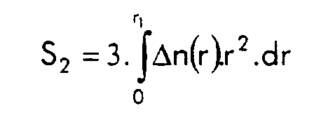
- le triple de l'intégrale du produit du carré du rayon par l'indice entre un rayon nul et le rayon (r1) extérieur de la partie centrale de la fibre présentant un indice supérieur à celui de la gaine compris entre 60.10-3 et 200.10-3 µm3, de préférence entre 70.10-3 et 150.10-3 µm3;
- le double de l'intégrale du produit du rayon par l'indice entre le rayon intérieur et le rayon extérieur de l'anneau compris entre 140.10-3 et 350.10-3 µm2, de préférence entre 160.10-3 et 310.10-3 µm2.
- figures 1 et 2, des représentations schématiques de modes de réalisation d'un système de transmission selon l'invention;
- figures 3 et 4, des exemples de profils de fibres selon l'invention.
- une dispersion chromatique inférieure ou égale à -20 ps/(nm.km), voire à -50 ps/(nm.km) à 1550 nm;
- un comportement monomode en câble dans la bande C, typiquement en dessous de 1580 nm;
- un comportement monomode en câble dans la bande L, typiquement en dessous de 1620 nm;
- une atténuation inférieure à 1 dB/km, voire à 0,8 dB/km à 1550 nm;
- un rapport entre la dispersion chromatique et l'atténuation inférieur ou égal à-100 ps/(nm.dB) à 1550 nm, et de préférence à -150 ps/(nm.dB) à 1550 nm ;
- une aire effective supérieure à 12 µm2, voire 15 µm2, et de préférence 20 µm2 à 1550 nm;
- des pertes par courbures inférieures à 400 dB/m, voire à 100 dB/m pour un enroulement de la fibre autour d'un manchon de rayon 10 mm, de 1530 nm à 1620 nm;
- des pertes par courbures inférieures à 0.05 dB, voire à 10-3 dB pour un enroulement de 100 tours avec un rayon de 30 mm, de 1530 nm à 1620 nm;
- une sensibilité aux micro-courbures inférieure à inférieure ou égale à 1, ou de préférence inférieure ou égale à 0,5 à 1550 nm ;
- une partie centrale avec un indice sensiblement constant supérieur ou égal à l'indice de la gaine;
- une partie annulaire d'indice inférieur ou égal à l'indice de la gaine ; l'ensemble constituant un profil d'indice dit "en rectangle avec une tranchée enterrée
- une partie centrale avec un indice sensiblement constant supérieur ou égal à l'indice de la gaine;
- une partie annulaire d'indice inférieur ou égal à l'indice de la gaine ; ces deux parties étant séparées par une partie annulaire dans laquelle l'indice décroít, de façon sensiblement linéaire. L'ensemble constitue un profil d'indice dit "en trapèze avec une tranchée enterrée ou déprimée".
| r1a (µm) | r1 (µm) | r1b (µm) | r2 (µm) | r3 (µm) | 103Δn1 | 103Δn2 | 103Δn3 | |
| Fibre 1 | 1,65 | 1,65 | 1,65 | 5 | 6,7 | 20,4 | -6,5 | 7 |
| Fibre 2 | 1,7 | 1,7 | 1,7 | 5,9 | 7,6 | 20,4 | -7,5 | 10,8 |
| Fibre 3 | 1,8 | 1,8 | 1,8 | 5,8 | 7,4 | 18,5 | -6,9 | 10,9 |
| Fibre 4 | 1,8 | 1,8 | 1,8 | 5,7 | 7,2 | 17,6 | -5,3 | 11,2 |
| Fibre 5 | 1,35 | 1,8 | 1,95 | 5,75 | 7,4 | 20,5 | -6,9 | 11 |
| Fibre 6 | 1,3 | 1,7 | 1,85 | 6 | 7,65 | 21,5 | -7 | 11 |
| Fibre 7 | 1,3 | 1,8 | 1,9 | 5,6 | 7,15 | 20,5 | -5,3 | 11 |
- λcth est la longueur d'onde de coupure théorique en nm;
- Seff est l'aire effective à 1550 nm en µm2;
- C est la dispersion chromatique à 1550 nm en ps/(nm.km);
- C' est la pente de dispersion chromatique à 1550 nm en ps/(nm2.km);
- C/C' est le rapport entre la dispersion chromatique et la pente de dispersion chromatique à 1550 nm, en nm;
- α est l'atténuation à 1550 nm, en dB/km;
- C/α est le rapport entre la dispersion chromatique et l'atténuation en ps/(nm.dB);
- PC1550 est la valeur des pertes par courbures à 1550 nm, en dB/m, pour un enroulement de la fibre autour d'un manchon de 10 mm de rayon;
- PC1620 est la valeur des pertes par courbures à 1620 nm, en dB/m, pour un enroulement de la fibre autour d'un manchon de 10 mm de rayon;
- Sµc est la sensibilitè aux micro-courbures mesurée comme expliqué ci-dessus à
1550 nm
λcth nm Seff µm2 C ps/(nm.km) C/C' nm α dB/km C/α ps/nm.dB PC1550 dB/m PC1620 dB/m Sµc 1 1710 18 -85 315 >0.60 >-150 0,1 5 <0.5 2 2015 16 -80 135 <0.65 <-130 0,2 15 <0.5 3 2010 19 -82 170 <0.5 <-150 0,3 15 <0.5 4 2010 23 -81 305 <0.5 <-150 0,2 5 <0.5 5 2100 17 -110 130 <0.65 <-150 0,6 40 <0.5 6 2070 20 -115 165 <0.6 <-200 0,3 20 <0.5 7 2050 21 -110 290 <0.6 <-200 0,3 10 <0.5


Claims (27)
- Une fibre optique présentant une longueur d'onde de coupure théorique supérieure ou égale à 1800 nm, une dispersion chromatique négative et supérieure ou égale à -150 ps/(nm.km) et un rapport entre la dispersion chromatique et la pente de dispersion chromatique entre 30 et 500 nm pour une longueur d'onde de 1550 nm.
- La fibre de la revendication 1, caractérisée en ce qu'elle présente des pertes par courbure inférieures à 400 dB/m, et de préférence inférieures à 100 dB/m, pour une longueur d'onde entre 1530 et 1620 nm, lorsque la fibre est enroulée sur un manchon de 10 mm de rayon.
- La fibre de la revendication 1 ou 2, caractérisée en ce qu'elle présente des pertes par courbure inférieures à 0,05 dB, et de préférence inférieures à 10-3 dB, pour une longueur d'onde entre 1530 et 1620 nm, pour un enroulement de 100 tours sur un manchon de 30 mm de rayon.
- La fibre de la revendication 1, 2 ou 3, caractérisée en ce qu'elle présente un rapport entre la dispersion chromatique et l'atténuation inférieur ou égal à-100 ps/(nm.dB), et de préférence inférieur ou égale à -150 ps/(nm.dB), pour une longueur d'onde entre 1530 et 1620 nm.
- La fibre de l'une des revendications 1 à 4, caractérisée en ce qu'elle présente pour une longueur d'onde de 1550 nm une aire effective supérieure ou égale à 12 µm2, de préférence supérieure ou égale à 15 µm2, voire à 20 µm2.
- La fibre de l'une des revendications 1 à 5, caractérisée en ce qu'elle présente une dispersion chromatique inférieure ou égale à -20 ps/(nm.km), de préférence inférieure ou égale à -50 ps/(nm.km), pour une longueur d'onde de 1550 nm.
- La fibre de l'une des revendications 1 à 6, caractérisée en ce qu'elle présente pour une longueur d'onde de 1550 nm une sensibilité aux micro-courbures inférieure ou égale à 1, et de préférence inférieure ou égale à 0,5.
- La fibre de l'une des revendications 1 à 7, caractérisée en ce qu'elle présente une différence entre l'indice en tout point de la fibre et l'indice de la gaine inférieure ou égale à 30.10-3, et de préférence inférieure ou égale à 25.10-3.
- La fibre de l'une des revendications 1 à 8, caractérisée en ce qu'elle présente une dispersion modale de polarisation inférieure ou égale à 0,5 ps/km1/2.
- La fibre de l'une des revendications 1 à 9, caractérisée en ce qu'elle présente une atténuation inférieure à 1 dB/km et de préférence inférieure à 0,8 dB/km.
- La fibre de l'une des revendications 1 à 10, caractérisée en ce qu'elle présente une longueur d'onde de coupure théorique supérieure ou égale à 1850 nm.
- La fibre selon l'une des revendications 1 à 11, caractérisée en ce qu'elle présente un profil d'indice en rectangle avec une tranchée déprimée et un anneau.
- La fibre selon l'une des revendications 1 à 11, caractérisée en ce qu'elle présente un profil d'indice en trapèze avec une tranchée déprimée et un anneau.
- La fibre de la revendication 12 ou 13, caractérisée en ce que la différence (Δn1) entre l'indice du rectangle ou du trapèze et l'indice de la gaine est comprise entre 16.10-3 et 24.10-3, et en ce que le rayon (r1) de la partie de la fibre présentant un indice supérieur à celui de la gaine est compris entre 1,5 et 2,3 µm.
- La fibre de la revendication 12, 13 ou 14, caractérisée en ce que la différence (Δn2) entre l'indice de la tranchée déprimée et l'indice de la gaine est comprise entre -7,5.10-3 et -3,5.10-3, et en ce que le rayon extérieur (r2) de cette tranchée est compris entre 4,5 et 6,9 µm.
- La fibre de l'une des revendications 12 à 15, caractérisée en ce que la différence (Δn3) entre l'indice de l'anneau et l'indice de la gaine est comprise entre 3.10-3 et 16.10-3, de préférence entre 3.10-3 et 14.10-3 et en ce que le rayon extérieur (r3) de cet anneau est compris entre 6,8 et 8,5 µm.
- La fibre de l'une des revendications 12 à 16, caractérisée en ce que le double de l'intégrale du produit du rayon par l'indice entre un rayon nul et le rayon (r1) extérieur de la partie centrale de la fibre présentant un indice supérieur à celui de la gaine est compris entre 40.10-3 et 100.10-3 µm2, de préférence entre 50.10-3 et 80.10-3 µm2.
- La fibre de l'une des revendications 12 à17, caractérisée en ce que le triple de l'intégrale du produit du carré du rayon par l'indice entre un rayon nul et le rayon (r1) extérieur de la partie centrale de la fibre présentant un indice supérieur à celui de la gaine est compris entre 60.10-3 et 200.10-3 µm3, de préférence entre 70.10-3 et 150.10-3 µm3.
- La fibre de l'une des revendications 12 à 18, caractérisée en ce que le double de l'intégrale du produit du rayon par l'indice entre le rayon intérieur et le rayon extérieur de l'anneau est compris entre 140.10-3 et 350.10-3 µm2, de préférence entre 160.10-3 et 310.10-3 µm2.
- Un système de transmission, dont la fibre de ligne comprend une fibre monomode à saut d'indice (4i, 12i), compensée en dispersion par une fibre selon l'une des revendications 1 à 19.
- Un système de transmission, dont la fibre de ligne comprend une fibre à dispersion décalée (4i, 12i), compensée en dispersion par une fibre selon l'une des revendications 1 à 19.
- Le système de la revendication 20 ou 21, caractérisé en ce que la dispersion chromatique cumulée pour chaque canal entre 1530 nm et 1610 nm est inférieure à 100 ps/nm, et de préférence inférieure à 50 ps/nm, en moyenne sur 100 km de transmission.
- Le système de la revendication 20 ou 22, caractérisé en ce que la fibre de ligne est constituée de fibre monomode à saut d'indice.
- Le système de la revendication 20 ou 22, caractérisé en ce que la fibre de ligne est constituée de fibre monomode à saut d'indice et de fibre (13i) selon l'une des revendications 1 à 19.
- Le système de la revendication 21 ou 22, caractérisé en ce que la fibre de ligne est constituée de fibre à dispersion décalée.
- Le système de la revendication 21 ou 22, caractérisé en ce que la fibre de ligne est constituée de fibre à dispersion décalée et de fibre (13i) selon l'une des revendications 1 à 19.
- Un module de compensation de dispersion, comprenant un amplificateur et une section de fibre selon l'une des revendications 1 à 19.
Applications Claiming Priority (2)
| Application Number | Priority Date | Filing Date | Title |
|---|---|---|---|
| FR0013209 | 2000-10-16 | ||
| FR0013209A FR2815418B1 (fr) | 2000-10-16 | 2000-10-16 | Fibre pour la compensation de dispersion chromatique d'une fibre nz-dsf a dispersion chromatique positive |
Publications (2)
| Publication Number | Publication Date |
|---|---|
| EP1217399A1 true EP1217399A1 (fr) | 2002-06-26 |
| EP1217399B1 EP1217399B1 (fr) | 2015-02-25 |
Family
ID=8855376
Family Applications (1)
| Application Number | Title | Priority Date | Filing Date |
|---|---|---|---|
| EP01402624.9A Expired - Lifetime EP1217399B1 (fr) | 2000-10-16 | 2001-10-11 | Fibre pour la compensation de dispersion chromatique d'une fibre NZ-DSF à dispersion chromatique positive |
Country Status (6)
| Country | Link |
|---|---|
| US (1) | US6668120B2 (fr) |
| EP (1) | EP1217399B1 (fr) |
| JP (1) | JP5112582B2 (fr) |
| CN (1) | CN1209643C (fr) |
| DK (1) | DK1217399T3 (fr) |
| FR (1) | FR2815418B1 (fr) |
Cited By (2)
| Publication number | Priority date | Publication date | Assignee | Title |
|---|---|---|---|---|
| WO2003040776A3 (fr) * | 2001-11-05 | 2003-11-27 | Corning Inc | Fibre de compensation de dispersion a pente fortement negative et systeme de transmission comprenant cette fibre |
| EP1484624A4 (fr) * | 2002-03-13 | 2005-08-17 | Fujikura Ltd | Fibre optique de compensation de dispersion |
Families Citing this family (14)
| Publication number | Priority date | Publication date | Assignee | Title |
|---|---|---|---|---|
| US7194171B2 (en) * | 1999-07-19 | 2007-03-20 | Sumitomo Electric Industries, Ltd. | Dispersion compensating optical fiber, dispersion compensating device, optical transmission line and optical transmission system |
| US6445864B2 (en) | 2000-03-24 | 2002-09-03 | Corning Incorporated | Dispersion compensating optical fiber |
| FR2815418B1 (fr) * | 2000-10-16 | 2003-05-16 | Cit Alcatel | Fibre pour la compensation de dispersion chromatique d'une fibre nz-dsf a dispersion chromatique positive |
| JP2002341157A (ja) * | 2001-03-15 | 2002-11-27 | Fujikura Ltd | 波長多重伝送路およびこれに用いる分散補償光ファイバ |
| FR2828939B1 (fr) * | 2001-08-27 | 2004-01-16 | Cit Alcatel | Fibre optique pour un systeme de transmission a multiplexage en longueurs d'onde |
| EP1474712A1 (fr) * | 2002-02-15 | 2004-11-10 | Corning Incorporated | Fibre optique decalee a dispersion de pente faible |
| US6975801B2 (en) | 2002-07-15 | 2005-12-13 | Corning Incorporated | Dispersion compensating fiber for low slope transmission fiber and optical transmission line utilizing same |
| FR2842610B1 (fr) * | 2002-07-18 | 2004-11-12 | Cit Alcatel | Fibre optique a gestion de dispersion |
| US6925237B2 (en) * | 2003-09-24 | 2005-08-02 | Corning Incorporated | High figure of merit dispersion compensating fiber for standard single mode fiber and transmission system utilizing same |
| US6985662B2 (en) * | 2003-10-30 | 2006-01-10 | Corning Incorporated | Dispersion compensating fiber for moderate dispersion NZDSF and transmission system utilizing same |
| FR2871899B1 (fr) * | 2004-06-22 | 2006-09-15 | Alcatel Sa | Fibre optique a compensation de dispersion chromatique |
| ATE460783T1 (de) * | 2005-01-04 | 2010-03-15 | Alcatel Lucent | Fortgeschrittene dispersionsabbildung für ein übertragungssystem mit dispersionsverschobenen fasern |
| FR2900739B1 (fr) * | 2006-05-03 | 2008-07-04 | Draka Comteq France | Fibre de compensation de la dispersion chromatique |
| CN109600804B (zh) * | 2017-09-30 | 2021-04-02 | 华为技术有限公司 | 一种安全保护的方法、装置和系统 |
Citations (5)
| Publication number | Priority date | Publication date | Assignee | Title |
|---|---|---|---|---|
| EP0668520A2 (fr) * | 1994-02-16 | 1995-08-23 | AT&T Corp. | Objet à guide d'onde optique à compensation de la dispersion |
| WO1999042869A1 (fr) * | 1998-02-23 | 1999-08-26 | Corning Incorporated | Guide d'onde gere en dispersion faible pente |
| US5995694A (en) * | 1996-06-21 | 1999-11-30 | The Furukawa Electric Co., Ltd. | Wavelength division multiplex communication link for optical transmission |
| EP1030199A1 (fr) * | 1999-02-18 | 2000-08-23 | Alcatel | Fibre de ligne pour systèmes de transmission à fibre optique à multiplexage en longueurs d'onde |
| EP1067412A1 (fr) * | 1999-06-29 | 2001-01-10 | Alcatel | Fibre optique à compensation de dispersion chromatique |
Family Cites Families (13)
| Publication number | Priority date | Publication date | Assignee | Title |
|---|---|---|---|---|
| US3508589A (en) * | 1967-10-27 | 1970-04-28 | Du Pont | Luminous textile products |
| JPH0776092B2 (ja) * | 1985-10-09 | 1995-08-16 | 住友電気工業株式会社 | ガラスの製造方法 |
| US5737472A (en) * | 1993-12-17 | 1998-04-07 | Audio-Images S.A.R.L. | Optical fiber with multiple point lateral illumination |
| AU693329B2 (en) * | 1995-04-13 | 1998-06-25 | Corning Incorporated | Dispersion managed optical waveguide |
| JP3760557B2 (ja) * | 1996-04-15 | 2006-03-29 | 住友電気工業株式会社 | 分散補償ファイバ及びそれを含む光伝送システム |
| US5781679A (en) * | 1997-05-09 | 1998-07-14 | Nec Research Institute, Inc. | Light dispersive optical fiber |
| JP3337943B2 (ja) * | 1997-05-20 | 2002-10-28 | 株式会社フジクラ | 分散補償光ファイバ |
| US5905837A (en) * | 1997-07-22 | 1999-05-18 | Nec Usa, Inc. | Side emitting optical fiber |
| AU1288899A (en) * | 1997-10-30 | 1999-05-24 | Miravant Systems, Inc. | Fiber optic diffuser and method of manufacture |
| CA2375267A1 (fr) * | 1999-06-18 | 2000-12-28 | Xijia Gu | Diffuseur a fibre optique |
| US6633714B2 (en) * | 2000-02-24 | 2003-10-14 | Alcatel | Optical fiber for wavelength division multiplex transmission systems |
| FR2815418B1 (fr) * | 2000-10-16 | 2003-05-16 | Cit Alcatel | Fibre pour la compensation de dispersion chromatique d'une fibre nz-dsf a dispersion chromatique positive |
| FR2815419B1 (fr) * | 2000-10-16 | 2003-10-03 | Cit Alcatel | Fibre pour la compensation de dispersion chromatique en bande d'une fibre monomode |
-
2000
- 2000-10-16 FR FR0013209A patent/FR2815418B1/fr not_active Expired - Lifetime
-
2001
- 2001-10-11 EP EP01402624.9A patent/EP1217399B1/fr not_active Expired - Lifetime
- 2001-10-11 DK DK01402624.9T patent/DK1217399T3/en active
- 2001-10-15 JP JP2001317302A patent/JP5112582B2/ja not_active Expired - Fee Related
- 2001-10-15 CN CNB011459123A patent/CN1209643C/zh not_active Expired - Lifetime
- 2001-10-15 US US09/976,012 patent/US6668120B2/en not_active Expired - Lifetime
Patent Citations (5)
| Publication number | Priority date | Publication date | Assignee | Title |
|---|---|---|---|---|
| EP0668520A2 (fr) * | 1994-02-16 | 1995-08-23 | AT&T Corp. | Objet à guide d'onde optique à compensation de la dispersion |
| US5995694A (en) * | 1996-06-21 | 1999-11-30 | The Furukawa Electric Co., Ltd. | Wavelength division multiplex communication link for optical transmission |
| WO1999042869A1 (fr) * | 1998-02-23 | 1999-08-26 | Corning Incorporated | Guide d'onde gere en dispersion faible pente |
| EP1030199A1 (fr) * | 1999-02-18 | 2000-08-23 | Alcatel | Fibre de ligne pour systèmes de transmission à fibre optique à multiplexage en longueurs d'onde |
| EP1067412A1 (fr) * | 1999-06-29 | 2001-01-10 | Alcatel | Fibre optique à compensation de dispersion chromatique |
Non-Patent Citations (1)
| Title |
|---|
| ANTOS A J ET AL: "DESIGN AND CHARACTERIZATION OF DISPERSION COMPENSATING FIBER BASED ON THE LP01 MODE", JOURNAL OF LIGHTWAVE TECHNOLOGY, IEEE. NEW YORK, US, vol. 12, no. 10, 1 October 1994 (1994-10-01), pages 1739 - 1744, XP000469527, ISSN: 0733-8724 * |
Cited By (4)
| Publication number | Priority date | Publication date | Assignee | Title |
|---|---|---|---|---|
| WO2003040776A3 (fr) * | 2001-11-05 | 2003-11-27 | Corning Inc | Fibre de compensation de dispersion a pente fortement negative et systeme de transmission comprenant cette fibre |
| US6711332B2 (en) | 2001-11-05 | 2004-03-23 | Corning Incorporated | Highly negative-slope dispersion compensating fiber and transmission system including same |
| EP1484624A4 (fr) * | 2002-03-13 | 2005-08-17 | Fujikura Ltd | Fibre optique de compensation de dispersion |
| US7233728B2 (en) | 2002-03-13 | 2007-06-19 | Fujikura Ltd. | Dispersion compensating optical fiber |
Also Published As
| Publication number | Publication date |
|---|---|
| EP1217399B1 (fr) | 2015-02-25 |
| US20020090186A1 (en) | 2002-07-11 |
| US6668120B2 (en) | 2003-12-23 |
| FR2815418A1 (fr) | 2002-04-19 |
| JP5112582B2 (ja) | 2013-01-09 |
| FR2815418B1 (fr) | 2003-05-16 |
| JP2002182057A (ja) | 2002-06-26 |
| CN1209643C (zh) | 2005-07-06 |
| DK1217399T3 (en) | 2015-05-26 |
| CN1373374A (zh) | 2002-10-09 |
Similar Documents
| Publication | Publication Date | Title |
|---|---|---|
| EP1030199B1 (fr) | Fibre de ligne pour systèmes de transmission à fibre optique à multiplexage en longueurs d'onde | |
| EP1067412B1 (fr) | Fibre optique à compensation de dispersion chromatique | |
| EP1217399B1 (fr) | Fibre pour la compensation de dispersion chromatique d'une fibre NZ-DSF à dispersion chromatique positive | |
| EP1288685A1 (fr) | Fibre optique pour un système de transmission à multiplexage en longueurs d'onde | |
| EP1764634A1 (fr) | Fibre de compensation de la dispersion chromatique et de la pente de dispersion cumulées | |
| EP0987569B1 (fr) | Fibre optique monomode à dispersion décalée optimisée pour les hauts débits | |
| EP1081514B1 (fr) | Fibre optique pour la compensation de la dispersion chromatique d'une fibre optique à dispersion chromatique positive | |
| EP1202087B1 (fr) | Fibre pour la compensation de la dispersion chromatique en bande S d'une fibre monomode | |
| EP0992817A1 (fr) | Fibre optique monomode à dispersion décalée à grande aire effective | |
| EP1018656B1 (fr) | Fibre optique à faible pente de dispersion chromatique | |
| EP1213595B1 (fr) | Compensation de la dispersion chromatique dans un système de transmission à fibre optique, et fibre de compensation | |
| EP1030200B1 (fr) | Fibre optique à grande surface effective et à forte dispersion chromatique | |
| EP1202088A1 (fr) | Fibre optique pour la compensation en ligne de la dispersion chromatique d'une fibre optique à dispersion chromatique positive | |
| EP1103830A1 (fr) | Fibre optique à dispersion chromatique décalée pour systèmes de transmission à fibre optique à multiplexage en longueurs d'onde | |
| EP1361685A1 (fr) | Fibre de compensation de la dispersion chromatique cumulée dans une fibre à dispersion chromatique négative | |
| EP1327898A1 (fr) | Fibre optique à profil d'indice complexe en forme d'anneaux | |
| EP1312950B1 (fr) | Fibre de compensation de dispersion chromatique pour système de transmission à fibre optique en bande u | |
| EP1291685B1 (fr) | Fibre à changement continu de dispersion chromatique | |
| EP1288682B1 (fr) | Fibre optique pour système de transmission à multiplexage en longueurs d'onde | |
| EP1018812B1 (fr) | Système de transmission à fibre optique à multiplexage en longueur d'onde avec compensation de la dispersion chromatique | |
| FR3154513A1 (fr) | Fibre optique monomode optimisée pour fonctionner en bande o et e, et système de transmission optique correspondant |
Legal Events
| Date | Code | Title | Description |
|---|---|---|---|
| PUAI | Public reference made under article 153(3) epc to a published international application that has entered the european phase |
Free format text: ORIGINAL CODE: 0009012 |
|
| AK | Designated contracting states |
Kind code of ref document: A1 Designated state(s): AT BE CH CY DE DK ES FI FR GB GR IE IT LI LU MC NL PT SE TR |
|
| AX | Request for extension of the european patent |
Free format text: AL;LT;LV;MK;RO;SI |
|
| 17P | Request for examination filed |
Effective date: 20021227 |
|
| AKX | Designation fees paid |
Designated state(s): AT BE CH CY DE DK ES FI FR GB GR IE IT LI LU MC NL PT SE TR |
|
| RAP1 | Party data changed (applicant data changed or rights of an application transferred) |
Owner name: DRAKA COMTEQ B.V. |
|
| 17Q | First examination report despatched |
Effective date: 20050603 |
|
| RAP1 | Party data changed (applicant data changed or rights of an application transferred) |
Owner name: DRAKA COMTEQ B.V. |
|
| RAP1 | Party data changed (applicant data changed or rights of an application transferred) |
Owner name: DRAKA COMTEQ B.V. |
|
| REG | Reference to a national code |
Ref country code: DE Ref legal event code: R079 Ref document number: 60149252 Country of ref document: DE Free format text: PREVIOUS MAIN CLASS: G02B0006160000 Ipc: G02B0006020000 |
|
| RIC1 | Information provided on ipc code assigned before grant |
Ipc: G02B 6/02 20060101AFI20140624BHEP |
|
| GRAP | Despatch of communication of intention to grant a patent |
Free format text: ORIGINAL CODE: EPIDOSNIGR1 |
|
| INTG | Intention to grant announced |
Effective date: 20140909 |
|
| INTG | Intention to grant announced |
Effective date: 20140916 |
|
| GRAS | Grant fee paid |
Free format text: ORIGINAL CODE: EPIDOSNIGR3 |
|
| GRAA | (expected) grant |
Free format text: ORIGINAL CODE: 0009210 |
|
| AK | Designated contracting states |
Kind code of ref document: B1 Designated state(s): AT BE CH CY DE DK ES FI FR GB GR IE IT LI LU MC NL PT SE TR |
|
| REG | Reference to a national code |
Ref country code: GB Ref legal event code: FG4D Free format text: NOT ENGLISH |
|
| REG | Reference to a national code |
Ref country code: CH Ref legal event code: EP |
|
| REG | Reference to a national code |
Ref country code: IE Ref legal event code: FG4D Free format text: LANGUAGE OF EP DOCUMENT: FRENCH |
|
| REG | Reference to a national code |
Ref country code: DE Ref legal event code: R096 Ref document number: 60149252 Country of ref document: DE Effective date: 20150402 |
|
| REG | Reference to a national code |
Ref country code: AT Ref legal event code: REF Ref document number: 712453 Country of ref document: AT Kind code of ref document: T Effective date: 20150415 |
|
| REG | Reference to a national code |
Ref country code: DK Ref legal event code: T3 Effective date: 20150522 |
|
| REG | Reference to a national code |
Ref country code: NL Ref legal event code: VDEP Effective date: 20150225 |
|
| REG | Reference to a national code |
Ref country code: AT Ref legal event code: MK05 Ref document number: 712453 Country of ref document: AT Kind code of ref document: T Effective date: 20150225 |
|
| PG25 | Lapsed in a contracting state [announced via postgrant information from national office to epo] |
Ref country code: SE Free format text: LAPSE BECAUSE OF FAILURE TO SUBMIT A TRANSLATION OF THE DESCRIPTION OR TO PAY THE FEE WITHIN THE PRESCRIBED TIME-LIMIT Effective date: 20150225 Ref country code: ES Free format text: LAPSE BECAUSE OF FAILURE TO SUBMIT A TRANSLATION OF THE DESCRIPTION OR TO PAY THE FEE WITHIN THE PRESCRIBED TIME-LIMIT Effective date: 20150225 Ref country code: FI Free format text: LAPSE BECAUSE OF FAILURE TO SUBMIT A TRANSLATION OF THE DESCRIPTION OR TO PAY THE FEE WITHIN THE PRESCRIBED TIME-LIMIT Effective date: 20150225 |
|
| PG25 | Lapsed in a contracting state [announced via postgrant information from national office to epo] |
Ref country code: GR Free format text: LAPSE BECAUSE OF FAILURE TO SUBMIT A TRANSLATION OF THE DESCRIPTION OR TO PAY THE FEE WITHIN THE PRESCRIBED TIME-LIMIT Effective date: 20150526 Ref country code: AT Free format text: LAPSE BECAUSE OF FAILURE TO SUBMIT A TRANSLATION OF THE DESCRIPTION OR TO PAY THE FEE WITHIN THE PRESCRIBED TIME-LIMIT Effective date: 20150225 |
|
| PG25 | Lapsed in a contracting state [announced via postgrant information from national office to epo] |
Ref country code: NL Free format text: LAPSE BECAUSE OF FAILURE TO SUBMIT A TRANSLATION OF THE DESCRIPTION OR TO PAY THE FEE WITHIN THE PRESCRIBED TIME-LIMIT Effective date: 20150225 |
|
| REG | Reference to a national code |
Ref country code: FR Ref legal event code: PLFP Year of fee payment: 15 |
|
| REG | Reference to a national code |
Ref country code: DE Ref legal event code: R097 Ref document number: 60149252 Country of ref document: DE |
|
| PG25 | Lapsed in a contracting state [announced via postgrant information from national office to epo] |
Ref country code: IT Free format text: LAPSE BECAUSE OF FAILURE TO SUBMIT A TRANSLATION OF THE DESCRIPTION OR TO PAY THE FEE WITHIN THE PRESCRIBED TIME-LIMIT Effective date: 20150225 |
|
| PLBE | No opposition filed within time limit |
Free format text: ORIGINAL CODE: 0009261 |
|
| STAA | Information on the status of an ep patent application or granted ep patent |
Free format text: STATUS: NO OPPOSITION FILED WITHIN TIME LIMIT |
|
| 26N | No opposition filed |
Effective date: 20151126 |
|
| PG25 | Lapsed in a contracting state [announced via postgrant information from national office to epo] |
Ref country code: LU Free format text: LAPSE BECAUSE OF FAILURE TO SUBMIT A TRANSLATION OF THE DESCRIPTION OR TO PAY THE FEE WITHIN THE PRESCRIBED TIME-LIMIT Effective date: 20151011 |
|
| REG | Reference to a national code |
Ref country code: CH Ref legal event code: PL |
|
| PG25 | Lapsed in a contracting state [announced via postgrant information from national office to epo] |
Ref country code: MC Free format text: LAPSE BECAUSE OF FAILURE TO SUBMIT A TRANSLATION OF THE DESCRIPTION OR TO PAY THE FEE WITHIN THE PRESCRIBED TIME-LIMIT Effective date: 20150225 |
|
| REG | Reference to a national code |
Ref country code: IE Ref legal event code: MM4A |
|
| PG25 | Lapsed in a contracting state [announced via postgrant information from national office to epo] |
Ref country code: LI Free format text: LAPSE BECAUSE OF NON-PAYMENT OF DUE FEES Effective date: 20151031 Ref country code: CH Free format text: LAPSE BECAUSE OF NON-PAYMENT OF DUE FEES Effective date: 20151031 |
|
| REG | Reference to a national code |
Ref country code: FR Ref legal event code: PLFP Year of fee payment: 16 |
|
| PG25 | Lapsed in a contracting state [announced via postgrant information from national office to epo] |
Ref country code: IE Free format text: LAPSE BECAUSE OF NON-PAYMENT OF DUE FEES Effective date: 20151011 |
|
| PG25 | Lapsed in a contracting state [announced via postgrant information from national office to epo] |
Ref country code: CY Free format text: LAPSE BECAUSE OF FAILURE TO SUBMIT A TRANSLATION OF THE DESCRIPTION OR TO PAY THE FEE WITHIN THE PRESCRIBED TIME-LIMIT Effective date: 20150225 |
|
| PG25 | Lapsed in a contracting state [announced via postgrant information from national office to epo] |
Ref country code: BE Free format text: LAPSE BECAUSE OF NON-PAYMENT OF DUE FEES Effective date: 20151031 |
|
| PG25 | Lapsed in a contracting state [announced via postgrant information from national office to epo] |
Ref country code: TR Free format text: LAPSE BECAUSE OF FAILURE TO SUBMIT A TRANSLATION OF THE DESCRIPTION OR TO PAY THE FEE WITHIN THE PRESCRIBED TIME-LIMIT Effective date: 20150225 |
|
| REG | Reference to a national code |
Ref country code: FR Ref legal event code: PLFP Year of fee payment: 17 |
|
| PG25 | Lapsed in a contracting state [announced via postgrant information from national office to epo] |
Ref country code: PT Free format text: LAPSE BECAUSE OF FAILURE TO SUBMIT A TRANSLATION OF THE DESCRIPTION OR TO PAY THE FEE WITHIN THE PRESCRIBED TIME-LIMIT Effective date: 20150225 |
|
| REG | Reference to a national code |
Ref country code: FR Ref legal event code: PLFP Year of fee payment: 18 |
|
| PGFP | Annual fee paid to national office [announced via postgrant information from national office to epo] |
Ref country code: DE Payment date: 20191029 Year of fee payment: 19 |
|
| PGFP | Annual fee paid to national office [announced via postgrant information from national office to epo] |
Ref country code: FR Payment date: 20191025 Year of fee payment: 19 Ref country code: DK Payment date: 20191029 Year of fee payment: 19 |
|
| PGFP | Annual fee paid to national office [announced via postgrant information from national office to epo] |
Ref country code: GB Payment date: 20191028 Year of fee payment: 19 |
|
| REG | Reference to a national code |
Ref country code: DE Ref legal event code: R119 Ref document number: 60149252 Country of ref document: DE |
|
| REG | Reference to a national code |
Ref country code: DK Ref legal event code: EBP Effective date: 20201031 |
|
| GBPC | Gb: european patent ceased through non-payment of renewal fee |
Effective date: 20201011 |
|
| PG25 | Lapsed in a contracting state [announced via postgrant information from national office to epo] |
Ref country code: DE Free format text: LAPSE BECAUSE OF NON-PAYMENT OF DUE FEES Effective date: 20210501 Ref country code: FR Free format text: LAPSE BECAUSE OF NON-PAYMENT OF DUE FEES Effective date: 20201031 |
|
| PG25 | Lapsed in a contracting state [announced via postgrant information from national office to epo] |
Ref country code: GB Free format text: LAPSE BECAUSE OF NON-PAYMENT OF DUE FEES Effective date: 20201011 |
|
| PG25 | Lapsed in a contracting state [announced via postgrant information from national office to epo] |
Ref country code: DK Free format text: LAPSE BECAUSE OF NON-PAYMENT OF DUE FEES Effective date: 20201031 |