EP1217202A1 - Procédé d'amortissement des ondes de pression dans une ligne hydraulique, et dispositif d'injection à rampe commune mettant en oeuvre ce procédé - Google Patents
Procédé d'amortissement des ondes de pression dans une ligne hydraulique, et dispositif d'injection à rampe commune mettant en oeuvre ce procédé Download PDFInfo
- Publication number
- EP1217202A1 EP1217202A1 EP01403248A EP01403248A EP1217202A1 EP 1217202 A1 EP1217202 A1 EP 1217202A1 EP 01403248 A EP01403248 A EP 01403248A EP 01403248 A EP01403248 A EP 01403248A EP 1217202 A1 EP1217202 A1 EP 1217202A1
- Authority
- EP
- European Patent Office
- Prior art keywords
- flow
- restriction
- pressure
- injection
- common rail
- Prior art date
- Legal status (The legal status is an assumption and is not a legal conclusion. Google has not performed a legal analysis and makes no representation as to the accuracy of the status listed.)
- Granted
Links
Images


Classifications
-
- F—MECHANICAL ENGINEERING; LIGHTING; HEATING; WEAPONS; BLASTING
- F02—COMBUSTION ENGINES; HOT-GAS OR COMBUSTION-PRODUCT ENGINE PLANTS
- F02M—SUPPLYING COMBUSTION ENGINES IN GENERAL WITH COMBUSTIBLE MIXTURES OR CONSTITUENTS THEREOF
- F02M55/00—Fuel-injection apparatus characterised by their fuel conduits or their venting means; Arrangements of conduits between fuel tank and pump F02M37/00
- F02M55/04—Means for damping vibrations or pressure fluctuations in injection pump inlets or outlets
-
- F—MECHANICAL ENGINEERING; LIGHTING; HEATING; WEAPONS; BLASTING
- F02—COMBUSTION ENGINES; HOT-GAS OR COMBUSTION-PRODUCT ENGINE PLANTS
- F02M—SUPPLYING COMBUSTION ENGINES IN GENERAL WITH COMBUSTIBLE MIXTURES OR CONSTITUENTS THEREOF
- F02M55/00—Fuel-injection apparatus characterised by their fuel conduits or their venting means; Arrangements of conduits between fuel tank and pump F02M37/00
- F02M55/02—Conduits between injection pumps and injectors, e.g. conduits between pump and common-rail or conduits between common-rail and injectors
- F02M55/025—Common rails
Definitions
- the present invention relates to a depreciation method pressure waves in a hydraulic line, using a restriction creating dissipation in the line, as well as a device common rail injection for motor vehicle engine, implementing this process.
- the flow of fuel injected is a function of the duration of piloting of the injector and of the pressure in the high pressure hydraulic circuit.
- a mapping installed in the calculator allows you to calculate the driving time of the injector on the basis of the requested flow (acceleration sensor) and the applied pressure (pressure sensor on rail).
- Another solution is a time correction activation of injectors during injection n ° 2 using an algorithm estimating the variations in the quantity injected, due to injection n ° 1.
- the second mapping does not can be established that once the parameters of injection no.1 have been set (the pressure disturbance is a function of these parameters).
- This solution is therefore by construction inactive during the development phase.
- the only parameter that is taken into account is the presence or not of a first injection, but in no way other parameters influencing the injection, such as the amount of the first injection, the gap time between the two consecutive injections, etc.
- this solution can only be used for a maximum of two consecutive injections.
- Solutions of the second type are very difficult to implement. point, given the large number of parameters to take into account account to write the correction algorithm (geometric dimensions of the fuel system, injection pressure, temperature, quantity injected during the first injection, quantity injected during the second injection, time interval between the two injections, etc.). Moreover, these solutions are very sensitive to industrial dispersions of manufacturing.
- the present invention aims to provide a solution to these interaction problems between consecutive injections, to cushion pressure waves generated by injection no.1 completely before starting injection number 2, without penalizing the injection pressure of the system.
- the invention relates to a method for damping pressure waves in a hydraulic line, by use of a restriction with a more favorable characteristic than that of a restriction constituted by a calibrated nozzle.
- a dissipator using a restriction operating in thin-film flow flow viscous, governed for example by Naviers-Stockes equations.
- Such a dissipator is obtained by forcing the passage of the fluid between two opposite walls very close to each other compared to the length of flow.
- a restriction having a height is therefore used very weak not only in relation to the length but also by in relation to the flow width.
- Another aspect of the invention relates to positioning optimal of a dissipator in a hydraulic line, in this case in a common rail injection device for a vehicle engine automobile, comprising for each cylinder an injector connected by a feed tube to a common rail.
- This device includes, in each feed tube, at the end of the ramp, a restriction operating in thin-film flow.
- a calibrated nozzle whose installation, in a line hydraulic, is the easiest way to dampen the waves of pressure, in order to create dissipation (pressure drop) in the line, has a parabolic characteristic of pressure drop depending on the debit, according to formula (1) above (see Figure 1).
- the thin layer condition relates the height h of the flow to the length 1 of the flow according to formula (2) above.
- Figure 3 shows, for comparison, the characteristic parabolic pressure drop of a calibrated nozzle, in dashes, and the linear characteristic of pressure drop of a working restriction in thin-film flow, in solid lines.
- pressure waves in a hydraulic line are accompanied by flow waves whose amplitudes are maximum in hydraulic line inlet (line flow belly).
- FIG 4 there is shown schematically a complete hydraulic injection line with supply tube 1 high pressure ranging from a common rail 2 to an injector 3 comprising a rod filter 4.
- FIG. 6 illustrates the effectiveness of the solution according to FIG. 4, showing that the damping of pressure variations at the inlet of the injector is much faster with the dissipator operating in thin-film flow at the outlet of common rail 2 (curve in dashes) than without sink (curve in solid line).
- the solution according to the invention limits the amplitude of the waves of pressure, which increases the reliability of the fuel system.
- the pressure in the high pressure circuit is more stable, which facilitates its regulation.
- the rod filter 4 generally present at the input of diesel injectors, has a layer pressure drop characteristic thin and can therefore be used not as a filter but as thin film heatsink. Its transfer from its current position to the inlet of the injector towards the outlet of the common rail, possibly accompanied by a lowering of its filtration threshold to increase the pressure drop, allows you to benefit practically without additional cost advantages of the dissipator, object of the present invention.
- Another solution is to use, in addition to the rod filter 4 in inlet of injector 3, a second rod filter at the outlet of the common rail, with a lowered filtration threshold.
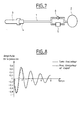
- Figure 8 compares the different efficiencies of a hydraulic line, one (in solid line) without dissipator, and the other (in dashes) with heatsink and non-return valve, as shown in Figure 7.
Landscapes
- Engineering & Computer Science (AREA)
- Chemical & Material Sciences (AREA)
- Combustion & Propulsion (AREA)
- Mechanical Engineering (AREA)
- General Engineering & Computer Science (AREA)
- Fuel-Injection Apparatus (AREA)
Abstract
Description
U désignant la vitesse caractéristique de l'écoulement, l la longueur de l'écoulement et ν la viscosité cinématique du fluide.
- la figure 1 représente la caractéristique de perte de charge d'un ajutage calibré en fonction du débit;
- la figure 2 est une vue en perspective d'une restriction fonctionnant en écoulement à couche mince;
- la figure 3 représente les caractéristiques de perte de charge d'un ajutage calibré et d'une restriction fonctionnant en écoulement à couche mince;
- la figure 4 représente une ligne hydraulique allant d'une rampe commune d'injection à un injecteur;
- la figure 5 représente les champs de pression et de débit sur la ligne de la figure 4;
- la figure 6 illustre de façon comparative l'efficacité d'amortissement d'une ligne hydraulique avec et sans dissipateur;
- la figure 7 représente une solution d'implantation d'un dissipateur avec clapet en parallèle; et
- la figure 8 illustre de façon comparative l'efficacité d'amortissement d'une ligne hydraulique sans dissipateur et d'une ligne avec dissipateur et clapet en parallèle, selon la figure 7.
Claims (6)
- Procédé d'amortissement des ondes de pression dans une ligne hydraulique, par utilisation d'une restriction créant une dissipation dans la ligne, caractérisé par le fait qu'on utilise une restriction fonctionnant en écoulement à couche mince.
- Procédé suivant la revendication 1, caractérisé par le fait qu'on utilise une restriction avec une hauteur d'écoulement très faible par rapport à la longueur d'écoulement.
- Procédé suivant la revendication 1 ou 2, caractérisé par le fait qu'on utilise une restriction ayant une hauteur d'écoulement très faible par rapport à la largeur d'écoulement.
- Dispositif d'injection à rampe commune pour moteur de véhicule automobile, comprenant pour chaque cylindre un injecteur relié par un tube d'alimentation à une rampe commune, caractérisé par le fait qu'il comprend, dans chaque tube d'alimentation (1), une restriction (5) fonctionnant en écoulement à couche mince.
- Dispositif suivant la revendication 4, caractérisé par le fait que la restriction (5) est disposée en sortie de rampe commune.
- Dispositif suivant la revendication 4 ou 5, caractérisé par le fait qu'il comprend un clapet anti-retour (6) monté en parallèle avec la restriction (5) en étant passant dans le sens rampe-injecteur.
Applications Claiming Priority (2)
| Application Number | Priority Date | Filing Date | Title |
|---|---|---|---|
| FR0016936A FR2818732B1 (fr) | 2000-12-22 | 2000-12-22 | Procede d'amortissement des ondes de pression dans une ligne hydraulique, et dispositif d'injection a rampe commune mettant en oeuvre ce procede |
| FR0016936 | 2000-12-22 |
Publications (2)
| Publication Number | Publication Date |
|---|---|
| EP1217202A1 true EP1217202A1 (fr) | 2002-06-26 |
| EP1217202B1 EP1217202B1 (fr) | 2008-06-25 |
Family
ID=8858121
Family Applications (1)
| Application Number | Title | Priority Date | Filing Date |
|---|---|---|---|
| EP01403248A Expired - Lifetime EP1217202B1 (fr) | 2000-12-22 | 2001-12-14 | Procédé et dispositif d'amortissement des ondes de pression dans un système d'injection à rampe commune |
Country Status (3)
| Country | Link |
|---|---|
| EP (1) | EP1217202B1 (fr) |
| DE (1) | DE60134528D1 (fr) |
| FR (1) | FR2818732B1 (fr) |
Cited By (12)
| Publication number | Priority date | Publication date | Assignee | Title |
|---|---|---|---|---|
| EP1300584A1 (fr) * | 2001-10-04 | 2003-04-09 | Renault S.A. | Dispositif d'alimentation en carburant pour moteur à combustion interne |
| WO2004033893A1 (fr) * | 2002-10-04 | 2004-04-22 | Robert Bosch Gmbh | Dispositif de suppression d'ondes de pression sur un systeme d'injection a accumulation |
| FR2848256A1 (fr) * | 2002-12-04 | 2004-06-11 | Renault Sa | Dispositif d'amortissement des ondes de pression pour systeme d'injection de carburant |
| FR2848257A1 (fr) * | 2002-12-04 | 2004-06-11 | Renault Sa | Dispositif d'amortissement des ondes de pression pour systeme d'injection de carburant |
| WO2004076846A1 (fr) * | 2003-02-25 | 2004-09-10 | Robert Bosch Gmbh | Conduite haute pression pour un systeme d'injection de carburant |
| EP1398496A3 (fr) * | 2002-09-09 | 2005-04-20 | Robert Bosch Gmbh | Conduite haute-pression pour système d'injection de carburant de moteur à combustion interne |
| EP1614894A1 (fr) | 2004-07-07 | 2006-01-11 | Renault s.a.s. | Dispositif d'injection a rampe commune avec amortissement des ondes de pression |
| FR2886350A1 (fr) * | 2005-05-26 | 2006-12-01 | Renault Sas | Procede d'amortissement d'ondes de pression et dispositif d'injection |
| FR2895033A3 (fr) | 2005-12-21 | 2007-06-22 | Renault Sas | Dispositif d'injection pour un moteur a combustion interne |
| AT501573B1 (de) * | 2006-06-13 | 2008-05-15 | Avl List Gmbh | Hydraulische vorrichtung mit zumindest einem druckspeicher |
| JP2009540196A (ja) * | 2006-06-13 | 2009-11-19 | ロバート ボッシュ ゲーエムベーハー | 燃料を内燃機関の燃焼室内に噴射するための装置 |
| WO2012058703A1 (fr) | 2010-11-02 | 2012-05-10 | Robert Bosch Gmbh | Dispositif pour injecter du carburant dans la chambre de combustion d'un moteur à combustion interne |
Families Citing this family (2)
| Publication number | Priority date | Publication date | Assignee | Title |
|---|---|---|---|---|
| FR2848258B1 (fr) | 2002-12-04 | 2006-06-23 | Renault Sa | Dispositif d'amortissement des ondes de pression pour systeme d'injection de carburant |
| CN105840373B (zh) * | 2016-03-24 | 2019-06-25 | 中国北方发动机研究所(天津) | 一种控制喷油“水击”压力波的装置 |
Citations (7)
| Publication number | Priority date | Publication date | Assignee | Title |
|---|---|---|---|---|
| US4003405A (en) * | 1975-03-26 | 1977-01-18 | Canadian Patents And Development Limited | Apparatus for regulating the flow rate of a fluid |
| US4625919A (en) * | 1983-12-02 | 1986-12-02 | Hitachi, Ltd. | Electromagnetic fuel injection valve |
| DE3822773A1 (de) * | 1988-07-01 | 1990-01-04 | Howaldtswerke Deutsche Werft | Einbauteil zur turbulenzdaempfung in rohrleitungen |
| US5297523A (en) * | 1993-02-26 | 1994-03-29 | Caterpillar Inc. | Tuned actuating fluid inlet manifold for a hydraulically-actuated fuel injection system |
| EP0780569A1 (fr) * | 1995-12-19 | 1997-06-25 | Nippon Soken, Inc. | Dispositif d'injection de carburant avec accumulateur |
| US5780748A (en) * | 1997-01-29 | 1998-07-14 | Hewlett-Packard Company | Flow device having parallel flow surfaces which move toward and away from one another to adjust the flow channel in proportion to applied force |
| US5979945A (en) * | 1996-12-07 | 1999-11-09 | Usuikokusai Sangyo Kaisha Ltd. | Common rail |
Family Cites Families (5)
| Publication number | Priority date | Publication date | Assignee | Title |
|---|---|---|---|---|
| DE1084086B (de) * | 1955-11-03 | 1960-06-23 | Maschf Augsburg Nuernberg Ag | Einrichtung zum besseren Zerstaeuben von schweren Brennstoffen bei Brennkraftmaschinen |
| DE19640085C2 (de) * | 1996-09-28 | 2001-10-25 | Orange Gmbh | Sperrventil zur Durchflußmengenbegrenzung |
| DE19739810C1 (de) * | 1997-09-10 | 1998-12-03 | Siemens Ag | Einspritzsystem für eine Brennkraftmaschine |
| US6237570B1 (en) * | 1997-10-09 | 2001-05-29 | Denso Corporation | Accumulator fuel injection apparatus |
| DE10006658B4 (de) * | 2000-02-15 | 2004-08-26 | Siemens Ag | Einspritzanlage |
-
2000
- 2000-12-22 FR FR0016936A patent/FR2818732B1/fr not_active Expired - Fee Related
-
2001
- 2001-12-14 EP EP01403248A patent/EP1217202B1/fr not_active Expired - Lifetime
- 2001-12-14 DE DE60134528T patent/DE60134528D1/de not_active Expired - Lifetime
Patent Citations (7)
| Publication number | Priority date | Publication date | Assignee | Title |
|---|---|---|---|---|
| US4003405A (en) * | 1975-03-26 | 1977-01-18 | Canadian Patents And Development Limited | Apparatus for regulating the flow rate of a fluid |
| US4625919A (en) * | 1983-12-02 | 1986-12-02 | Hitachi, Ltd. | Electromagnetic fuel injection valve |
| DE3822773A1 (de) * | 1988-07-01 | 1990-01-04 | Howaldtswerke Deutsche Werft | Einbauteil zur turbulenzdaempfung in rohrleitungen |
| US5297523A (en) * | 1993-02-26 | 1994-03-29 | Caterpillar Inc. | Tuned actuating fluid inlet manifold for a hydraulically-actuated fuel injection system |
| EP0780569A1 (fr) * | 1995-12-19 | 1997-06-25 | Nippon Soken, Inc. | Dispositif d'injection de carburant avec accumulateur |
| US5979945A (en) * | 1996-12-07 | 1999-11-09 | Usuikokusai Sangyo Kaisha Ltd. | Common rail |
| US5780748A (en) * | 1997-01-29 | 1998-07-14 | Hewlett-Packard Company | Flow device having parallel flow surfaces which move toward and away from one another to adjust the flow channel in proportion to applied force |
Cited By (15)
| Publication number | Priority date | Publication date | Assignee | Title |
|---|---|---|---|---|
| EP1300584A1 (fr) * | 2001-10-04 | 2003-04-09 | Renault S.A. | Dispositif d'alimentation en carburant pour moteur à combustion interne |
| EP1398496A3 (fr) * | 2002-09-09 | 2005-04-20 | Robert Bosch Gmbh | Conduite haute-pression pour système d'injection de carburant de moteur à combustion interne |
| WO2004033893A1 (fr) * | 2002-10-04 | 2004-04-22 | Robert Bosch Gmbh | Dispositif de suppression d'ondes de pression sur un systeme d'injection a accumulation |
| FR2848256A1 (fr) * | 2002-12-04 | 2004-06-11 | Renault Sa | Dispositif d'amortissement des ondes de pression pour systeme d'injection de carburant |
| FR2848257A1 (fr) * | 2002-12-04 | 2004-06-11 | Renault Sa | Dispositif d'amortissement des ondes de pression pour systeme d'injection de carburant |
| CN1745243B (zh) * | 2003-02-25 | 2013-05-01 | 罗伯特·博世有限公司 | 用于燃料喷射装置的高压管道 |
| WO2004076846A1 (fr) * | 2003-02-25 | 2004-09-10 | Robert Bosch Gmbh | Conduite haute pression pour un systeme d'injection de carburant |
| EP1614894A1 (fr) | 2004-07-07 | 2006-01-11 | Renault s.a.s. | Dispositif d'injection a rampe commune avec amortissement des ondes de pression |
| FR2872865A1 (fr) * | 2004-07-07 | 2006-01-13 | Renault Sas | Dispositif d'injection a rampe commune avec amortissement des ondes de pression |
| FR2886350A1 (fr) * | 2005-05-26 | 2006-12-01 | Renault Sas | Procede d'amortissement d'ondes de pression et dispositif d'injection |
| FR2895033A3 (fr) | 2005-12-21 | 2007-06-22 | Renault Sas | Dispositif d'injection pour un moteur a combustion interne |
| AT501573B1 (de) * | 2006-06-13 | 2008-05-15 | Avl List Gmbh | Hydraulische vorrichtung mit zumindest einem druckspeicher |
| JP2009540196A (ja) * | 2006-06-13 | 2009-11-19 | ロバート ボッシュ ゲーエムベーハー | 燃料を内燃機関の燃焼室内に噴射するための装置 |
| WO2012058703A1 (fr) | 2010-11-02 | 2012-05-10 | Robert Bosch Gmbh | Dispositif pour injecter du carburant dans la chambre de combustion d'un moteur à combustion interne |
| US9447720B2 (en) | 2010-11-02 | 2016-09-20 | Robert Bosch Gmbh | Device for injecting fuel into the combustion chamber of an internal combustion engine |
Also Published As
| Publication number | Publication date |
|---|---|
| DE60134528D1 (de) | 2008-08-07 |
| FR2818732A1 (fr) | 2002-06-28 |
| EP1217202B1 (fr) | 2008-06-25 |
| FR2818732B1 (fr) | 2004-05-28 |
Similar Documents
| Publication | Publication Date | Title |
|---|---|---|
| EP1217202B1 (fr) | Procédé et dispositif d'amortissement des ondes de pression dans un système d'injection à rampe commune | |
| EP1086304B1 (fr) | Systeme de regeneration pour un filtre a particules de gaz d'echappement de moteur diesel | |
| FR2727470A1 (fr) | Ensemble a clapet pour circuit de carburant sans retour | |
| EP1030052A1 (fr) | Système d'injection de carburant sous haute pression dans un moteur à combustion interne à injection directe | |
| EP0886039B1 (fr) | Procédé et ensemble d'élimination des oxydes d'azote présents dans des gaz d'échappement, utilisant un echangeur thermique | |
| CA2461353A1 (fr) | Dispositif d'injection d'air de refroidissement dans un rotor de turbine | |
| FR2846048A1 (fr) | Procede et dispositif de commande d'une unite motrice munie d'un moteur a combustion interne | |
| WO2011110760A2 (fr) | Procede de regulation de la temperature de regeneration d'un filtre a particules | |
| EP2452060B1 (fr) | Procede de controle d'un debit d'air injecte dans un moteur, ensemble comprenant un calculateur mettant en uvre le procede et un vehicule comprenant l'ensemble | |
| EP0958448B1 (fr) | Procede de controle du debit d'huile dans un moteur deux temps a graissage separe et un moteur associe | |
| EP1300584A1 (fr) | Dispositif d'alimentation en carburant pour moteur à combustion interne | |
| EP1400679B1 (fr) | Système de contrôle du fonctionnement d'un moteur diesel de véhicule automobile | |
| FR2891876A3 (fr) | Dispositif d'injection a rampe commune pour moteur a combustion interne et injection de carburant. | |
| EP2900988B1 (fr) | Procédé de commande d'un groupe motopropulseur, véhicule, support d'enregistrement et programme associés | |
| EP4598684A1 (fr) | Système de projection de fluide de nettoyage avec deux buses de projection et une valve directionnelle | |
| EP1426610B1 (fr) | Dispositif d'amortissement des ondes de pression pour système d'injection de carburant | |
| FR2872865A1 (fr) | Dispositif d'injection a rampe commune avec amortissement des ondes de pression | |
| EP3207237A1 (fr) | Moteur à combustion interne d'un véhicule automobile pourvu d'une désactivation de cylindre | |
| FR2740178A1 (fr) | Systeme d'injection de carburant dans un moteur a combustion interne | |
| FR2862102A1 (fr) | Systeme d'aide a la regeneration de moyens de depollution d'un moteur de vehicule | |
| FR2855850A1 (fr) | Procede et dispositif de gestion d'un moteur a combustion interne d'un vehicule automobile | |
| FR2863315A1 (fr) | Dispositif d'alimentation de carburant pour systeme d'injection de carburant | |
| CH703279A2 (fr) | Amortisseur pneumatique pour capsule manométrique de correction des pompes à injection mécanique pour moteur diesel suralimenté. | |
| FR2841833A1 (fr) | Adaptation optimale du couple roue en descente | |
| WO1998016737A1 (fr) | Systeme d'injection de carburant dans un moteur a combustion interne |
Legal Events
| Date | Code | Title | Description |
|---|---|---|---|
| PUAI | Public reference made under article 153(3) epc to a published international application that has entered the european phase |
Free format text: ORIGINAL CODE: 0009012 |
|
| AK | Designated contracting states |
Kind code of ref document: A1 Designated state(s): AT BE CH CY DE DK ES FI FR GB GR IE IT LI LU MC NL PT SE TR |
|
| AX | Request for extension of the european patent |
Free format text: AL;LT;LV;MK;RO;SI |
|
| RAP1 | Party data changed (applicant data changed or rights of an application transferred) |
Owner name: RENAULT S.A.S. |
|
| AKX | Designation fees paid | ||
| 17P | Request for examination filed |
Effective date: 20021205 |
|
| RBV | Designated contracting states (corrected) |
Designated state(s): BE DE ES |
|
| REG | Reference to a national code |
Ref country code: DE Ref legal event code: 8566 |
|
| 17Q | First examination report despatched |
Effective date: 20060905 |
|
| 17Q | First examination report despatched |
Effective date: 20060905 |
|
| GRAP | Despatch of communication of intention to grant a patent |
Free format text: ORIGINAL CODE: EPIDOSNIGR1 |
|
| RTI1 | Title (correction) |
Free format text: METHOD AND APPARATUS OF DAMPING PRESSURE WAVES IN A COMMON RAIL INJECTION SYSTEM |
|
| GRAS | Grant fee paid |
Free format text: ORIGINAL CODE: EPIDOSNIGR3 |
|
| GRAA | (expected) grant |
Free format text: ORIGINAL CODE: 0009210 |
|
| AK | Designated contracting states |
Kind code of ref document: B1 Designated state(s): BE DE ES |
|
| REF | Corresponds to: |
Ref document number: 60134528 Country of ref document: DE Date of ref document: 20080807 Kind code of ref document: P |
|
| PG25 | Lapsed in a contracting state [announced via postgrant information from national office to epo] |
Ref country code: ES Free format text: LAPSE BECAUSE OF FAILURE TO SUBMIT A TRANSLATION OF THE DESCRIPTION OR TO PAY THE FEE WITHIN THE PRESCRIBED TIME-LIMIT Effective date: 20081006 |
|
| PLBE | No opposition filed within time limit |
Free format text: ORIGINAL CODE: 0009261 |
|
| STAA | Information on the status of an ep patent application or granted ep patent |
Free format text: STATUS: NO OPPOSITION FILED WITHIN TIME LIMIT |
|
| 26N | No opposition filed |
Effective date: 20090326 |
|
| BERE | Be: lapsed |
Owner name: RENAULT S.A.S. Effective date: 20081231 |
|
| PG25 | Lapsed in a contracting state [announced via postgrant information from national office to epo] |
Ref country code: BE Free format text: LAPSE BECAUSE OF NON-PAYMENT OF DUE FEES Effective date: 20081231 |
|
| PGFP | Annual fee paid to national office [announced via postgrant information from national office to epo] |
Ref country code: DE Payment date: 20141211 Year of fee payment: 14 |
|
| REG | Reference to a national code |
Ref country code: DE Ref legal event code: R119 Ref document number: 60134528 Country of ref document: DE |
|
| PG25 | Lapsed in a contracting state [announced via postgrant information from national office to epo] |
Ref country code: DE Free format text: LAPSE BECAUSE OF NON-PAYMENT OF DUE FEES Effective date: 20160701 |