EP1217183A1 - Freistrahlzentrifuge mit integriertem Ölabscheider - Google Patents
Freistrahlzentrifuge mit integriertem Ölabscheider Download PDFInfo
- Publication number
- EP1217183A1 EP1217183A1 EP01126924A EP01126924A EP1217183A1 EP 1217183 A1 EP1217183 A1 EP 1217183A1 EP 01126924 A EP01126924 A EP 01126924A EP 01126924 A EP01126924 A EP 01126924A EP 1217183 A1 EP1217183 A1 EP 1217183A1
- Authority
- EP
- European Patent Office
- Prior art keywords
- rotor
- oil
- housing
- crankcase
- free jet
- Prior art date
- Legal status (The legal status is an assumption and is not a legal conclusion. Google has not performed a legal analysis and makes no representation as to the accuracy of the status listed.)
- Withdrawn
Links
- 239000007789 gas Substances 0.000 claims abstract description 54
- 239000003921 oil Substances 0.000 claims abstract description 44
- 239000010687 lubricating oil Substances 0.000 claims abstract description 21
- 239000003595 mist Substances 0.000 claims abstract description 9
- 238000004140 cleaning Methods 0.000 claims abstract description 6
- 238000002485 combustion reaction Methods 0.000 claims description 14
- 229910000831 Steel Inorganic materials 0.000 claims 2
- 239000010959 steel Substances 0.000 claims 2
- 238000005507 spraying Methods 0.000 claims 1
- 238000000926 separation method Methods 0.000 description 9
- 230000000694 effects Effects 0.000 description 4
- 239000002245 particle Substances 0.000 description 3
- 238000010276 construction Methods 0.000 description 2
- 238000009434 installation Methods 0.000 description 2
- 238000004519 manufacturing process Methods 0.000 description 2
- 238000005201 scrubbing Methods 0.000 description 2
- 230000004888 barrier function Effects 0.000 description 1
- 238000006243 chemical reaction Methods 0.000 description 1
- 238000011161 development Methods 0.000 description 1
- 230000018109 developmental process Effects 0.000 description 1
- 238000010586 diagram Methods 0.000 description 1
- 238000005461 lubrication Methods 0.000 description 1
- 238000012423 maintenance Methods 0.000 description 1
- 239000000463 material Substances 0.000 description 1
- 238000000746 purification Methods 0.000 description 1
- 239000007787 solid Substances 0.000 description 1
Images
Classifications
-
- F—MECHANICAL ENGINEERING; LIGHTING; HEATING; WEAPONS; BLASTING
- F01—MACHINES OR ENGINES IN GENERAL; ENGINE PLANTS IN GENERAL; STEAM ENGINES
- F01M—LUBRICATING OF MACHINES OR ENGINES IN GENERAL; LUBRICATING INTERNAL COMBUSTION ENGINES; CRANKCASE VENTILATING
- F01M13/00—Crankcase ventilating or breathing
- F01M13/04—Crankcase ventilating or breathing having means for purifying air before leaving crankcase, e.g. removing oil
-
- B—PERFORMING OPERATIONS; TRANSPORTING
- B04—CENTRIFUGAL APPARATUS OR MACHINES FOR CARRYING-OUT PHYSICAL OR CHEMICAL PROCESSES
- B04B—CENTRIFUGES
- B04B5/00—Other centrifuges
- B04B5/005—Centrifugal separators or filters for fluid circulation systems, e.g. for lubricant oil circulation systems
-
- F—MECHANICAL ENGINEERING; LIGHTING; HEATING; WEAPONS; BLASTING
- F01—MACHINES OR ENGINES IN GENERAL; ENGINE PLANTS IN GENERAL; STEAM ENGINES
- F01M—LUBRICATING OF MACHINES OR ENGINES IN GENERAL; LUBRICATING INTERNAL COMBUSTION ENGINES; CRANKCASE VENTILATING
- F01M13/00—Crankcase ventilating or breathing
- F01M13/04—Crankcase ventilating or breathing having means for purifying air before leaving crankcase, e.g. removing oil
- F01M2013/0422—Separating oil and gas with a centrifuge device
Definitions
- the invention relates to a free jet centrifuge for the lubricating oil of an internal combustion engine, in which an oil separator for crankcase gases of the internal combustion engine is integrated, according to the genus of patent claim 1.
- Free jet centrifuges of the type described in the introduction are known. For example, shows the only figure according to DE 43 11 906 A1 such a free jet centrifuge. This is driven by the lubricating oil to be centrifuged via reaction nozzles 34. The high speeds of the centrifuge rotor are used to generate the crankcase gas Clean residues with the help of centrifugal rings 70. The crankcase gas will withdrawn via a suction line 52.
- the object of the invention is therefore a device for cleaning crankcase gases to create, which by a free jet centrifuge for the lubricating oil of an internal combustion engine is formed, and which are sufficiently high degrees of separation for residues from the crankcase gas. This object is achieved by the features of the claim 1 solved.
- the free jet centrifuge according to the invention has a housing, which each with an oil inlet and outlet as well as a supply line and a suction line for the crankcase gas Is provided.
- the oil supply is directly with the inside of the centrifuge rotor connected so that the lubricating oil to be cleaned can be introduced directly there can. This leaves the rotor through the drive nozzles, thus entering the housing and is brought back into the oil circuit through the oil drain.
- the supply line is connected to the crankcase in such a way that the crankcase gases can get into the housing of the oil centrifuge without increased flow loss. Due to the high speed of the rotor, the oil as it passes by removed from the crankcase gases to the casing through the suction line leave in a clean condition.
- connection channel opens into the housing of the free jet centrifuge. It is possible that the oil drain and the supply line meet to form the connection channel together. A sufficiently long common channel section must be formed here, so that the crankcase gas can be pre-separated. Another possibility is that from the crankcase a single connection channel directly into the centrifuge housing is directed.
- the connecting channel leads to a simpler construction of the apparatus and thereby greater economy.
- the cross-section of the connecting channel must be chosen in this way that, even with large blow-by quantities, the cleaned lubricating oil produced by the centrifuge runs into the oil pan and can flow freely.
- an additional scrubbing effect of the crankcase gas is thereby achieved, by the oil droplets in the crankcase gas due to the return flow cleaned lubricating oil. It is therefore particularly advantageous that the Volume containing the oil mist generated by the drive nozzles of the rotor, extends into the connecting channel. So that the scrubbing effect is as possible large flow path of the crankcase gas expanded.
- a special embodiment of the centrifuge provides that the rotor guide vanes on has outer circumference. These serve to accelerate the crankcase gas in Circumferential direction of the rotor. This will remove residues in the crankcase gas improved according to the mechanism of the centrifuge. Through the Centrifugal force deposits the residues on the housing wall and to the connecting channel transported to the housing. The crankcase gas extracted through the suction line thus achieves a higher degree of purity.
- the pressure control valve which is provided for the discharge of the crankcase gases in the housing structure of the Housing can be integrated. This primarily means manufacturing and material costs saved. Therefore, this measure leads to a higher profitability of the proposed solution.
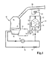
- an internal combustion engine 10 and a centrifuge 11 for cleaning the Lubricating oil for the internal combustion engine is shown schematically as a block diagram.
- the Centrifuge has a housing 12 and a rotor 13 which is rotatably mounted in the housing is.
- the centrifuge is set in rotation by a drive nozzle 14. Doing so it is supplied by an oil circuit 15 with lubricating oil to be cleaned.
- the oil circuit is schematically reduced to a pump 16 and a lubrication point 17. Included in the oil circuit is also an oil pan 18 of the internal combustion engine.
- the centrifuge is related arranged on the oil circuit 15 in the bypass.
- the cleaned lubricating oil which has emerged through the drive nozzle 14, the housing via an oil drain 19 returned to the oil pan.
- the supply is achieved via an oil inlet 20.
- a supply line 21 is provided on the housing, through which crankcase gases introduced from the internal combustion engine into the housing 12 of the centrifuge can be.
- the discharge point is located in an area in the housing forms a volume 22 for the oil mist generated by the drive nozzle 14.
- the nozzle needs this relaxation space to turn the rotor. feed 21 and oil drain 19 open into a connecting channel 27, which is therefore in both Directions is flowed through and a correspondingly large cross section available must face.
- crankcase gas reaches the rotor, along it the walls of the housing must pass to a suction line 23 in volume 22 opposite part of the housing.
- a suction line 23 in volume 22 opposite part of the housing.
- Guide vanes 24 set in a rotary motion around the rotor.
- Crankcase gas particles and oil droplets on the wall of the housing 12 deposited.
- the crankcase gas cleaned in this way leaves the housing 12 through the Suction line 23 and passes a pressure control valve 25. If this is open, it will Crankcase gas sucked through an intake tract 26 of the internal combustion engine.
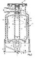
- FIG. 12 A detailed configuration of the centrifuge can be seen in FIG. Instead of an oil supply and a feed line here is a common connection channel 27 on the housing 12 provided.
- the housing is sealed with the help of the installation site sealed, the installation location may be the internal combustion engine itself. Under These requirements form particularly short paths for the supply of the crankcase gas or the lubricating oil.
- the housing consists of a housing base 28, which with the help of a molded seal 29 is attached to the internal combustion engine, not shown.
- a screw bell 30 in which the pressure control valve as an integral part 25 is housed.
- a spring biased by a spring 32 acts in this Diaphragm 33, which leads to a closure of a valve seat 34, provided the vacuum in the intake tract, not shown, of the internal combustion engine becomes too large.
- the rotor 13 in plastic construction consists of two shells welded together 35 and is in a ball bearing 36 and a plain bearing 37, which is also an inlet 38 forms in the rotor for the lubricating oil, rotatably mounted in the housing 12.
- the feed on Lubricating oil can be influenced by an inlet valve 39.
- the lubricating oil circuit in the centrifuge is by solid arrows, the flow of the Crankcase gas indicated by dashed arrows.
- the lubricating oil gets over the inlet valve 39 and the inlet 38 into a central tube 40 of the rotor and from there Openings 41 in a separation space 42 of the rotor. With separation of the dirt particles on the outer walls of the rotor, the oil flow leaves the rotor through the drive nozzle 14 and a washer nozzle 43.
- the washer nozzle 43 generates a jet directed radially away from the rotor, which is used to wash out residues from the Crankcase gas leads.
- the crankcase gas is indicated by points in volume 22. From the volume, the lubricating oil leaves, which is on a housing base 44 collects, the housing through the connecting channel 27.
- crankcase gas flows against the returning lubricating oil. This will, after it has left the connecting channel 27, introduced directly into the volume 22. There are no barriers or baffles to prevent the crankcase gas from reaching you Mixing with the oil mist. This effectively removes residues from the crankcase gas. Then this is along the guide vanes 24 passed to the upper part of the housing and from there into the pressure control valve 25. On At this point, the crankcase gas is largely free of residues, which is why it can be easily burned in the internal combustion engine.
Landscapes
- Engineering & Computer Science (AREA)
- Mechanical Engineering (AREA)
- General Engineering & Computer Science (AREA)
- Lubrication Details And Ventilation Of Internal Combustion Engines (AREA)
Abstract
Description
- Figur 1
- die Anordnung einer kombinierten Schmierölzentrifunge mit Kurbelgehäusegasabscheidung und
- Figur 2
- den Aufbau der erfindungsgemäßen Zentrifuge im Mittelschnitt.
Claims (6)
- Freistrahlzentrifuge für das Schmieröl einer Brennkraftmaschine, wobei ein Rotor (13) der Freistrahlzentrifuge als Ölabscheider für im Kurbelgehäusegas enthaltene Rückstände ausgeführt ist, aufweisend ein Gehäuse (12), in dem der Rotor (13) drehbar gelagert ist mitwobei die Zuführleitung (21) derart an das Gehäuse (12) angeschlossen ist, dass das zugeführte Kurbelgehäusegas durch ein Volumen (22) geführt wird, in dem sich der durch Antriebsdüsen (14) des Rotors (13) erzeugte Ölnebel befindet, dadurch gekennzeichnet, dass der Ölablauf und die Zuführleitung zumindest teilweise durch einen einzigen Verbindungskanal (27) gebildet werden, der in das Gehäuse (12) der Freistrahlzentrifuge mündet.einem Ölzulauf (20) zur Speisung des Rotors (13) mit dem zu reinigenden Schmieröl,einem Ölablauf (19) für das gereinigte Schmieröl,einer Zuführleitung (21) für die zu reinigenden Kurbelgehäusegase undeiner Saugleitung (23) für die gereinigten Kurbelgehäusegase,
- Freistrahlzentrifuge nach Anspruch 2, dadurch gekennzeichnet, dass das Volumen (22) für den Ölnebel sich in den Verbindungskanal hinein erstreckt.
- Freistahlzentrifuge nach einem der vorherigen Ansprüche, dadurch gekennzeichnet, dass der Rotor (13) zumindest am Außenumfang mit Leitschaufeln (24) zur Beschleunigung des Kurbelgehäusegases in Umfangsrichtung des Rotors ausgestattet ist.
- Freistrahlzentrifuge nach einem der vorherigen Ansprüche, dadurch gekennzeichnet, dass der Rotor mindestens eine zusätzliche Wäscherdüse (43) zur Verbesserung der Reinigung der Kurbelgehäusegase aufweist.
- Freistahlzentrifunge nach Anspruch 5, dadurch gekennzeichnet, dass die Spritzrichtung der Wäscherdüse (43) bezogen auf eine Drehachse des Rotors radial nach außen weist.
- Freistrahlzentrifuge nach einem der vorherigen Ansprüche, dadurch gekennzeichnet, dass in das Gehäuse (12) ein Druckregelventil (25) für das Kurbelgehäusegas integriert ist.
Applications Claiming Priority (2)
| Application Number | Priority Date | Filing Date | Title |
|---|---|---|---|
| DE10063903 | 2000-12-21 | ||
| DE10063903A DE10063903A1 (de) | 2000-12-21 | 2000-12-21 | Freistrahlzentrifuge mit integriertem Ölabscheider |
Publications (1)
| Publication Number | Publication Date |
|---|---|
| EP1217183A1 true EP1217183A1 (de) | 2002-06-26 |
Family
ID=7668223
Family Applications (1)
| Application Number | Title | Priority Date | Filing Date |
|---|---|---|---|
| EP01126924A Withdrawn EP1217183A1 (de) | 2000-12-21 | 2001-11-13 | Freistrahlzentrifuge mit integriertem Ölabscheider |
Country Status (3)
| Country | Link |
|---|---|
| US (1) | US20020088445A1 (de) |
| EP (1) | EP1217183A1 (de) |
| DE (1) | DE10063903A1 (de) |
Cited By (8)
| Publication number | Priority date | Publication date | Assignee | Title |
|---|---|---|---|---|
| WO2003037521A1 (en) * | 2001-11-01 | 2003-05-08 | Alfa Laval Corporate Ab | An apparatus for simultaneous cleaning of a liquid and a gas |
| WO2003061838A1 (en) * | 2002-01-25 | 2003-07-31 | Alfa Laval Corporate Ab | An apparatus for simultaneous cleaning of a liquid and a gas |
| FR2878290A1 (fr) * | 2004-11-19 | 2006-05-26 | Renault Sas | Dispositif de depollution et de recirculation des gaz contournant le piston d'un moteur a combustion interne |
| US7182724B2 (en) | 2004-02-25 | 2007-02-27 | Fleetguard, Inc. | Disposable centrifuge rotor |
| US7338546B2 (en) | 2006-04-19 | 2008-03-04 | Alfa Laval Corporate Ab | Centrifugal separator for cleaning gas generated by an internal combustion engine and a method for operating the same |
| WO2009010248A3 (de) * | 2007-07-13 | 2009-06-11 | Hengst Gmbh & Co Kg | Abscheider zum abscheiden von ölnebel aus dem kurbelgehäuseentlüftungsgas einer brennkraftmaschine sowie funktionsmodul und brennkraftmaschine mit einem abscheider |
| WO2011110628A1 (de) * | 2010-03-11 | 2011-09-15 | Hengst Gmbh & Co. Kg | Ölnebelabscheider und brennkraftmaschine mit einem ölnebelabscheider |
| EP2832448A1 (de) * | 2013-07-31 | 2015-02-04 | Mann + Hummel Gmbh | Ölzentrifuge mit Zentrifugenrotor |
Families Citing this family (26)
| Publication number | Priority date | Publication date | Assignee | Title |
|---|---|---|---|---|
| DE20118388U1 (de) * | 2001-11-13 | 2003-03-27 | Hengst GmbH & Co.KG, 48147 Münster | Einrichtung für die Kurbelgehäuse-Entlüftung einer Brennkraftmaschine |
| DE10254034A1 (de) * | 2002-11-20 | 2004-06-03 | Mann + Hummel Gmbh | Fliehkraftabscheider |
| US7428898B2 (en) * | 2004-01-28 | 2008-09-30 | New Condensator, Inc. | Apparatus for removing contaminants from crankcase emissions |
| RU2350763C2 (ru) * | 2004-01-28 | 2009-03-27 | Нью Конденсейтор, Инк. | Сепаратор для отделения жидкостей из потока текучей среды (варианты) |
| GB2425077B (en) * | 2005-04-15 | 2009-11-18 | Mann & Hummel Gmbh | Centifrugal separator and rotor therefor |
| WO2006119737A1 (de) | 2005-05-10 | 2006-11-16 | Mahle International Gmbh | In eine axial hohle welle eines verbrennungsmotors integrierte zentrifugal-ölnebelabscheidereinrichtung |
| DE102005023227A1 (de) * | 2005-05-20 | 2006-07-13 | Audi Ag | Ölabscheidersystem |
| DE202007001989U1 (de) * | 2007-02-10 | 2008-06-19 | Hengst Gmbh & Co.Kg | Schmierölkreislauf einer Brennkraftmaschine und Ölmodul dafür |
| US7699029B2 (en) * | 2007-07-26 | 2010-04-20 | Cummins Filtration Ip, Inc. | Crankcase ventilation system with pumped scavenged oil |
| DE202007010792U1 (de) * | 2007-08-01 | 2008-12-11 | Hengst Gmbh & Co.Kg | Abscheider zum Abscheiden von Ölnebel aus dem Kurbelgehäuseentlüftungsgas einer Brennkraftmaschine und Brennkraftmaschine mit einem Abscheider |
| KR100974591B1 (ko) * | 2007-11-29 | 2010-08-06 | 현대자동차주식회사 | 크랭크 케이스 환기 장치 |
| DE102009035895B4 (de) | 2009-08-03 | 2012-05-16 | Mann + Hummel Gmbh | Filteranordnung |
| DE102011120782A1 (de) * | 2011-12-09 | 2013-06-13 | Volkswagen Aktiengesellschaft | Brennkraftmaschine und Verfahren zum Betrieb einer Brennkraftmaschine |
| WO2014155614A1 (ja) * | 2013-03-28 | 2014-10-02 | 東京濾器株式会社 | オイルセパレータ |
| EP2980373B1 (de) * | 2013-03-28 | 2020-07-29 | Tokyo Roki Co., Ltd. | Ölabscheider |
| US10252280B2 (en) * | 2013-07-31 | 2019-04-09 | Mann+Hummel Gmbh | Oil centrifuge having a throttle point and safety valve |
| DE112014005241B4 (de) | 2013-11-18 | 2023-05-17 | Cummins Filtration Ip, Inc. | Kurbelgehäuseentlüftungssystem und Schmiersystem für einen Verbrennungsmotor |
| EP3112032B1 (de) * | 2014-02-25 | 2020-05-27 | Tokyo Roki Co., Ltd. | Ölabscheider |
| US10569206B2 (en) * | 2014-02-26 | 2020-02-25 | Tokyo Roki Co., Ltd. | Oil separator |
| DE102015205557B4 (de) * | 2015-03-26 | 2017-05-24 | Mtu Friedrichshafen Gmbh | Brennkraftmaschine und Verfahren zum Betreiben einer Brennkraftmaschine |
| US11654385B2 (en) | 2015-09-24 | 2023-05-23 | Cummins Filtration Ip, Inc | Utilizing a mechanical seal between a filter media and an endcap of a rotating filter cartridge |
| US10132217B2 (en) * | 2016-03-24 | 2018-11-20 | Caterpillar Inc. | Floating crankcase ventilation system and method |
| DE102016012209B3 (de) | 2016-10-12 | 2018-03-29 | Audi Ag | Brennkraftmaschine mit einem Zylinderkurbelgehäuse |
| DE102017207869A1 (de) * | 2017-05-10 | 2018-11-15 | Mahle International Gmbh | Turboladerentlüftungseinrichtung |
| WO2018236921A1 (en) | 2017-06-20 | 2018-12-27 | Cummins Filtration Ip, Inc. | CENTRIFUGAL SEPARATOR WITH AXIAL FLOW |
| EP3801828B1 (de) | 2018-05-24 | 2025-11-26 | Cummins Filtration IP, Inc. | Verdrehsicherung für kurbelgehäuseentlüftungsfilter |
Citations (4)
| Publication number | Priority date | Publication date | Assignee | Title |
|---|---|---|---|---|
| DE4311906A1 (de) | 1993-04-10 | 1994-10-13 | Audi Ag | Vorrichtung zum Entlüften des Kurbelgehäuses einer Brennkraftmaschine |
| WO1999056883A1 (en) | 1998-05-04 | 1999-11-11 | Alfa Laval Ab | Method and plant for cleaning of gases from a combustion engine |
| US6095964A (en) * | 1995-12-23 | 2000-08-01 | The Glacier Metal Company Limited | Centrifugal separator with weight thrust bearing |
| DE19914166A1 (de) * | 1999-03-29 | 2000-10-05 | Deutz Ag | Ölabscheider zur Reinigung von Kurbelgehäuseentlüftungsgasen einer Brennkraftmaschine |
Family Cites Families (4)
| Publication number | Priority date | Publication date | Assignee | Title |
|---|---|---|---|---|
| CH532422A (de) * | 1970-12-23 | 1973-01-15 | Sulzer Ag | Zentrifugiereinrichtung zur Reinigung eines Betriebsmittels einer Kolbenbrennkraftmaschine |
| DE4403425A1 (de) * | 1993-02-20 | 1994-08-25 | Audi Ag | Verfahren und Vorrichtung zur Überwachung der Funktion einer Freistrahl-Zentrifuge in Druckumlauf-Schmiersystem |
| DE4444344C1 (de) * | 1994-12-14 | 1996-04-04 | Hengst Walter Gmbh & Co Kg | Freistrahlzentrifuge |
| GB2317203B (en) * | 1996-09-13 | 2000-03-08 | Glacier Metal Co Ltd | I C engine crankcase breather assembly |
-
2000
- 2000-12-21 DE DE10063903A patent/DE10063903A1/de not_active Withdrawn
-
2001
- 2001-11-13 EP EP01126924A patent/EP1217183A1/de not_active Withdrawn
- 2001-12-21 US US10/024,572 patent/US20020088445A1/en not_active Abandoned
Patent Citations (4)
| Publication number | Priority date | Publication date | Assignee | Title |
|---|---|---|---|---|
| DE4311906A1 (de) | 1993-04-10 | 1994-10-13 | Audi Ag | Vorrichtung zum Entlüften des Kurbelgehäuses einer Brennkraftmaschine |
| US6095964A (en) * | 1995-12-23 | 2000-08-01 | The Glacier Metal Company Limited | Centrifugal separator with weight thrust bearing |
| WO1999056883A1 (en) | 1998-05-04 | 1999-11-11 | Alfa Laval Ab | Method and plant for cleaning of gases from a combustion engine |
| DE19914166A1 (de) * | 1999-03-29 | 2000-10-05 | Deutz Ag | Ölabscheider zur Reinigung von Kurbelgehäuseentlüftungsgasen einer Brennkraftmaschine |
Cited By (14)
| Publication number | Priority date | Publication date | Assignee | Title |
|---|---|---|---|---|
| US7156901B2 (en) | 2001-11-01 | 2007-01-02 | Alfa Laval Corporate Ab | Apparatus for simultaneous cleaning of a liquid and a gas |
| WO2003037521A1 (en) * | 2001-11-01 | 2003-05-08 | Alfa Laval Corporate Ab | An apparatus for simultaneous cleaning of a liquid and a gas |
| US7081146B2 (en) | 2001-11-01 | 2006-07-25 | Alfa Laval Corporate Ab | Apparatus for simultaneous cleaning of a liquid and a gas |
| WO2003061838A1 (en) * | 2002-01-25 | 2003-07-31 | Alfa Laval Corporate Ab | An apparatus for simultaneous cleaning of a liquid and a gas |
| US7077881B2 (en) | 2002-01-25 | 2006-07-18 | Alfa Laval Corporate Ab | Apparatus for simultaneous cleaning of a liquid and a gas |
| US7182724B2 (en) | 2004-02-25 | 2007-02-27 | Fleetguard, Inc. | Disposable centrifuge rotor |
| FR2878290A1 (fr) * | 2004-11-19 | 2006-05-26 | Renault Sas | Dispositif de depollution et de recirculation des gaz contournant le piston d'un moteur a combustion interne |
| US7338546B2 (en) | 2006-04-19 | 2008-03-04 | Alfa Laval Corporate Ab | Centrifugal separator for cleaning gas generated by an internal combustion engine and a method for operating the same |
| WO2009010248A3 (de) * | 2007-07-13 | 2009-06-11 | Hengst Gmbh & Co Kg | Abscheider zum abscheiden von ölnebel aus dem kurbelgehäuseentlüftungsgas einer brennkraftmaschine sowie funktionsmodul und brennkraftmaschine mit einem abscheider |
| US8714132B2 (en) | 2007-07-13 | 2014-05-06 | Hengst Gmbh & Co. Kg | Separator for separating oil mist from the crankcase ventilation gas of an internal combustion engine, and functional module and internal combustion engine comprising a separator |
| WO2011110628A1 (de) * | 2010-03-11 | 2011-09-15 | Hengst Gmbh & Co. Kg | Ölnebelabscheider und brennkraftmaschine mit einem ölnebelabscheider |
| EP2832448A1 (de) * | 2013-07-31 | 2015-02-04 | Mann + Hummel Gmbh | Ölzentrifuge mit Zentrifugenrotor |
| US20150038310A1 (en) * | 2013-07-31 | 2015-02-05 | Mann+Hummel Gmbh | Oil Centrifuge with Centrifuge Rotor |
| US9844785B2 (en) * | 2013-07-31 | 2017-12-19 | Mann+Hummel Gmbh | Oil centrifuge having a throttle point and safety valve |
Also Published As
| Publication number | Publication date |
|---|---|
| DE10063903A1 (de) | 2002-07-04 |
| US20020088445A1 (en) | 2002-07-11 |
Similar Documents
| Publication | Publication Date | Title |
|---|---|---|
| DE10063903A1 (de) | Freistrahlzentrifuge mit integriertem Ölabscheider | |
| EP2021591B1 (de) | Zylinderkopf eines verbrennungsmotors | |
| DE10350562B4 (de) | Vorrichtung zur Aufbereitung von Schmieröl | |
| EP2052136B1 (de) | Vorrichtung zur abscheidung von flüssigkeiten aus gasen | |
| EP2167235B1 (de) | Brennkraftmaschine mit einem abscheider zum abscheiden von ölnebel aus dem kurbelgehäuseentlüftungsgas | |
| EP2009288A2 (de) | Turbolader mit integriertem Separator | |
| DE69614595T2 (de) | Zyklonabscheider mit Koaleszenzelement | |
| DE19803872A1 (de) | Entlüfungsvorrichtung für ein Kurbelgehäuse einer Brennkraftmaschine | |
| DE112015006228T5 (de) | Mehrstufige rotierende Tropfenabscheidervorrichtungen | |
| DE102006024816A1 (de) | Einrichtung für die Entlüftung eines Kurbelgehäuses | |
| DE10330296A1 (de) | Abscheidevorrichtung | |
| EP0946251B1 (de) | Vorrichtung zum abscheiden von flüssigkeiten und/oder feststoffen oder gasen mit anderem spezifischem gewicht aus einem gasstrom | |
| DE19914166A1 (de) | Ölabscheider zur Reinigung von Kurbelgehäuseentlüftungsgasen einer Brennkraftmaschine | |
| DE102010015838A1 (de) | Ölabscheider eines Entlüftungssystems | |
| EP2821599A1 (de) | Strahltriebwerk mit wenigstens einem Ölabscheider | |
| DE7834796U1 (de) | Vorreiniger fuer verbrennungsmaschinen | |
| DE102004045630A1 (de) | Zentrifugalabscheider | |
| DE10323792A1 (de) | Vorrichtung zur Reinigung eines Gasstromes | |
| EP2994236A1 (de) | Vorrichtung und verfahren zum abscheiden von fremdpartikeln aus einem gasstrom | |
| DE102009035895B4 (de) | Filteranordnung | |
| DE19642218A1 (de) | Ölabscheidevorrichtung | |
| EP2255883A1 (de) | Zyklonabscheidevorrichtung | |
| DE102016216826A1 (de) | Flüssigkeitsnebelabscheideeinrichtung und Kurbelgehäuseentlüftungseinrichtung | |
| DE202013101966U1 (de) | Vorrichtung zum Abscheiden von Fremdpartikeln aus einem Gasstrom | |
| DE8816486U1 (de) | Vorrichtung zur Aerosolabscheidung aus Abgasen |
Legal Events
| Date | Code | Title | Description |
|---|---|---|---|
| PUAI | Public reference made under article 153(3) epc to a published international application that has entered the european phase |
Free format text: ORIGINAL CODE: 0009012 |
|
| AK | Designated contracting states |
Kind code of ref document: A1 Designated state(s): AT BE CH CY DE DK ES FI FR GB GR IE IT LI LU MC NL PT SE TR |
|
| AX | Request for extension of the european patent |
Free format text: AL;LT;LV;MK;RO;SI |
|
| TPAD | Observations filed by third parties |
Free format text: ORIGINAL CODE: EPIDOS TIPA |
|
| 17P | Request for examination filed |
Effective date: 20020710 |
|
| AKX | Designation fees paid |
Designated state(s): AT BE CH CY DE DK ES FI FR GB GR IE IT LI LU MC NL PT SE TR |
|
| RAP1 | Party data changed (applicant data changed or rights of an application transferred) |
Owner name: MANN + HUMMEL GMBH |
|
| STAA | Information on the status of an ep patent application or granted ep patent |
Free format text: STATUS: THE APPLICATION IS DEEMED TO BE WITHDRAWN |
|
| 18D | Application deemed to be withdrawn |
Effective date: 20040602 |