EP1216968A1 - Method and apparatus for ultraviolet curing - Google Patents
Method and apparatus for ultraviolet curing Download PDFInfo
- Publication number
- EP1216968A1 EP1216968A1 EP01403108A EP01403108A EP1216968A1 EP 1216968 A1 EP1216968 A1 EP 1216968A1 EP 01403108 A EP01403108 A EP 01403108A EP 01403108 A EP01403108 A EP 01403108A EP 1216968 A1 EP1216968 A1 EP 1216968A1
- Authority
- EP
- European Patent Office
- Prior art keywords
- ultraviolet light
- emitting device
- light emitting
- tubular
- cooling medium
- Prior art date
- Legal status (The legal status is an assumption and is not a legal conclusion. Google has not performed a legal analysis and makes no representation as to the accuracy of the status listed.)
- Granted
Links
- 238000000034 method Methods 0.000 title claims abstract description 32
- 230000005855 radiation Effects 0.000 claims abstract description 82
- 239000002826 coolant Substances 0.000 claims abstract description 66
- 239000011261 inert gas Substances 0.000 claims abstract description 29
- 238000001816 cooling Methods 0.000 claims abstract description 24
- 239000007789 gas Substances 0.000 claims description 9
- 239000007788 liquid Substances 0.000 claims description 8
- 238000003780 insertion Methods 0.000 claims 2
- 230000037431 insertion Effects 0.000 claims 2
- 238000010438 heat treatment Methods 0.000 claims 1
- 238000000576 coating method Methods 0.000 abstract description 74
- 238000001723 curing Methods 0.000 abstract description 59
- 239000000835 fiber Substances 0.000 abstract description 37
- 239000013307 optical fiber Substances 0.000 abstract description 27
- 230000008569 process Effects 0.000 abstract description 16
- 238000003848 UV Light-Curing Methods 0.000 abstract description 8
- 238000004519 manufacturing process Methods 0.000 abstract description 6
- 238000003847 radiation curing Methods 0.000 abstract 1
- 239000000758 substrate Substances 0.000 description 61
- 239000011248 coating agent Substances 0.000 description 53
- 230000001965 increasing effect Effects 0.000 description 14
- CBENFWSGALASAD-UHFFFAOYSA-N Ozone Chemical compound [O-][O+]=O CBENFWSGALASAD-UHFFFAOYSA-N 0.000 description 12
- QVGXLLKOCUKJST-UHFFFAOYSA-N atomic oxygen Chemical compound [O] QVGXLLKOCUKJST-UHFFFAOYSA-N 0.000 description 12
- 239000001301 oxygen Substances 0.000 description 12
- 229910052760 oxygen Inorganic materials 0.000 description 12
- IJGRMHOSHXDMSA-UHFFFAOYSA-N Atomic nitrogen Chemical compound N#N IJGRMHOSHXDMSA-UHFFFAOYSA-N 0.000 description 11
- 239000000463 material Substances 0.000 description 11
- 239000003039 volatile agent Substances 0.000 description 9
- 230000002411 adverse Effects 0.000 description 6
- 238000006116 polymerization reaction Methods 0.000 description 6
- 238000012546 transfer Methods 0.000 description 5
- 239000012809 cooling fluid Substances 0.000 description 4
- 239000003365 glass fiber Substances 0.000 description 4
- 239000011159 matrix material Substances 0.000 description 4
- 229910052757 nitrogen Inorganic materials 0.000 description 4
- 230000008021 deposition Effects 0.000 description 3
- 229910001873 dinitrogen Inorganic materials 0.000 description 3
- 239000012530 fluid Substances 0.000 description 3
- 230000000670 limiting effect Effects 0.000 description 3
- XKRFYHLGVUSROY-UHFFFAOYSA-N Argon Chemical compound [Ar] XKRFYHLGVUSROY-UHFFFAOYSA-N 0.000 description 2
- 230000004913 activation Effects 0.000 description 2
- 230000008901 benefit Effects 0.000 description 2
- 238000006243 chemical reaction Methods 0.000 description 2
- 238000004891 communication Methods 0.000 description 2
- 230000007613 environmental effect Effects 0.000 description 2
- 239000011521 glass Substances 0.000 description 2
- 239000003504 photosensitizing agent Substances 0.000 description 2
- 230000002829 reductive effect Effects 0.000 description 2
- XLYOFNOQVPJJNP-UHFFFAOYSA-N water Chemical compound O XLYOFNOQVPJJNP-UHFFFAOYSA-N 0.000 description 2
- 238000010521 absorption reaction Methods 0.000 description 1
- 230000001133 acceleration Effects 0.000 description 1
- 238000009825 accumulation Methods 0.000 description 1
- 239000000654 additive Substances 0.000 description 1
- 229910052786 argon Inorganic materials 0.000 description 1
- 230000005540 biological transmission Effects 0.000 description 1
- 239000003054 catalyst Substances 0.000 description 1
- 238000007796 conventional method Methods 0.000 description 1
- 230000003247 decreasing effect Effects 0.000 description 1
- 230000000779 depleting effect Effects 0.000 description 1
- 238000013461 design Methods 0.000 description 1
- 230000001066 destructive effect Effects 0.000 description 1
- 238000011161 development Methods 0.000 description 1
- 239000012153 distilled water Substances 0.000 description 1
- 229920006240 drawn fiber Polymers 0.000 description 1
- 239000003814 drug Substances 0.000 description 1
- 230000000694 effects Effects 0.000 description 1
- 238000005516 engineering process Methods 0.000 description 1
- 230000002708 enhancing effect Effects 0.000 description 1
- 238000000605 extraction Methods 0.000 description 1
- 238000012681 fiber drawing Methods 0.000 description 1
- 238000007380 fibre production Methods 0.000 description 1
- 230000036541 health Effects 0.000 description 1
- 239000012535 impurity Substances 0.000 description 1
- 230000003993 interaction Effects 0.000 description 1
- 238000002844 melting Methods 0.000 description 1
- 230000008018 melting Effects 0.000 description 1
- QSHDDOUJBYECFT-UHFFFAOYSA-N mercury Chemical compound [Hg] QSHDDOUJBYECFT-UHFFFAOYSA-N 0.000 description 1
- 229910052753 mercury Inorganic materials 0.000 description 1
- 229910001507 metal halide Inorganic materials 0.000 description 1
- 150000005309 metal halides Chemical class 0.000 description 1
- 239000000203 mixture Substances 0.000 description 1
- 230000003287 optical effect Effects 0.000 description 1
- 238000013021 overheating Methods 0.000 description 1
- 239000002245 particle Substances 0.000 description 1
- 230000021715 photosynthesis, light harvesting Effects 0.000 description 1
- 230000001681 protective effect Effects 0.000 description 1
- 239000010453 quartz Substances 0.000 description 1
- 230000035939 shock Effects 0.000 description 1
- VYPSYNLAJGMNEJ-UHFFFAOYSA-N silicon dioxide Inorganic materials O=[Si]=O VYPSYNLAJGMNEJ-UHFFFAOYSA-N 0.000 description 1
- 239000007787 solid Substances 0.000 description 1
- 238000001228 spectrum Methods 0.000 description 1
- 229910052724 xenon Inorganic materials 0.000 description 1
- FHNFHKCVQCLJFQ-UHFFFAOYSA-N xenon atom Chemical compound [Xe] FHNFHKCVQCLJFQ-UHFFFAOYSA-N 0.000 description 1
Images

Classifications
-
- C—CHEMISTRY; METALLURGY
- C03—GLASS; MINERAL OR SLAG WOOL
- C03C—CHEMICAL COMPOSITION OF GLASSES, GLAZES OR VITREOUS ENAMELS; SURFACE TREATMENT OF GLASS; SURFACE TREATMENT OF FIBRES OR FILAMENTS MADE FROM GLASS, MINERALS OR SLAGS; JOINING GLASS TO GLASS OR OTHER MATERIALS
- C03C25/00—Surface treatment of fibres or filaments made from glass, minerals or slags
- C03C25/10—Coating
- C03C25/12—General methods of coating; Devices therefor
-
- H—ELECTRICITY
- H01—ELECTRIC ELEMENTS
- H01J—ELECTRIC DISCHARGE TUBES OR DISCHARGE LAMPS
- H01J65/00—Lamps without any electrode inside the vessel; Lamps with at least one main electrode outside the vessel
- H01J65/04—Lamps in which a gas filling is excited to luminesce by an external electromagnetic field or by external corpuscular radiation, e.g. for indicating plasma display panels
- H01J65/042—Lamps in which a gas filling is excited to luminesce by an external electromagnetic field or by external corpuscular radiation, e.g. for indicating plasma display panels by an external electromagnetic field
- H01J65/044—Lamps in which a gas filling is excited to luminesce by an external electromagnetic field or by external corpuscular radiation, e.g. for indicating plasma display panels by an external electromagnetic field the field being produced by a separate microwave unit
-
- B—PERFORMING OPERATIONS; TRANSPORTING
- B29—WORKING OF PLASTICS; WORKING OF SUBSTANCES IN A PLASTIC STATE IN GENERAL
- B29C—SHAPING OR JOINING OF PLASTICS; SHAPING OF MATERIAL IN A PLASTIC STATE, NOT OTHERWISE PROVIDED FOR; AFTER-TREATMENT OF THE SHAPED PRODUCTS, e.g. REPAIRING
- B29C35/00—Heating, cooling or curing, e.g. crosslinking or vulcanising; Apparatus therefor
- B29C35/02—Heating or curing, e.g. crosslinking or vulcanizing during moulding, e.g. in a mould
- B29C35/08—Heating or curing, e.g. crosslinking or vulcanizing during moulding, e.g. in a mould by wave energy or particle radiation
- B29C35/0805—Heating or curing, e.g. crosslinking or vulcanizing during moulding, e.g. in a mould by wave energy or particle radiation using electromagnetic radiation
- B29C2035/0827—Heating or curing, e.g. crosslinking or vulcanizing during moulding, e.g. in a mould by wave energy or particle radiation using electromagnetic radiation using UV radiation
-
- B—PERFORMING OPERATIONS; TRANSPORTING
- B29—WORKING OF PLASTICS; WORKING OF SUBSTANCES IN A PLASTIC STATE IN GENERAL
- B29C—SHAPING OR JOINING OF PLASTICS; SHAPING OF MATERIAL IN A PLASTIC STATE, NOT OTHERWISE PROVIDED FOR; AFTER-TREATMENT OF THE SHAPED PRODUCTS, e.g. REPAIRING
- B29C35/00—Heating, cooling or curing, e.g. crosslinking or vulcanising; Apparatus therefor
- B29C35/02—Heating or curing, e.g. crosslinking or vulcanizing during moulding, e.g. in a mould
- B29C35/08—Heating or curing, e.g. crosslinking or vulcanizing during moulding, e.g. in a mould by wave energy or particle radiation
- B29C35/10—Heating or curing, e.g. crosslinking or vulcanizing during moulding, e.g. in a mould by wave energy or particle radiation for articles of indefinite length
Definitions
- the present invention generally relates to the field of optical fibers, in particular the present invention is directed to a new and novel method and apparatus for curing optical fibers with ultraviolet radiation.
- Optical fibers are very small diameter glass strands which are capable of transmitting an optical signal over great distances, at high speeds, and with relatively low signal loss as compared to standard wire or cable networks.
- the use of optical fibers in today's technology has developed into many widespread areas, such as: medicine, aviation, communications, etc. Because of this development, there is a growing need to produce optical fibers of better quality at faster rates and lower costs.
- optical fibers such as communications
- the primary coating is applied onto the surface of the optical fiber, with the secondary coating being applied on top of the primary coating.
- the main function of the primary coating is to provide a soft "cushion" for the glass fiber, protecting it from shock damage.
- the main purpose of the secondary coating is to provide a semi-rigid protective shell to protect both the primary coating and the glass fiber from adverse environmental elements, as well as physical damage.
- UV photoinitiators function by absorbing energy which is radiated by a UV, or sometimes a visible, light source. This energy absorption then initiates polymerization of the liquid coating placed on the fiber, and accelerates the hardening of the coating. This acceleration greatly reduces the production time of optical fibers, making production more profitable.
- the curing of the coatings take place in specific UV curing stages during the optical fiber manufacturing process. There are curing “chambers" at these stages which facilitate the curing of the coatings.
- UV light source which emits UV radiation or light onto the optical fiber coating. It should also be noted that this curing step is also found when manufacturing fiber optic cables or ribbons, when the cable or ribbon matrix or substrate is to be cured around a plurality of fibers. In either application, the basic function and operation of the UV curing chamber remains the same.
- prior art curing devices use mirrors or reflective surfaces inside the curing chamber to reflect the UV radiation from the bulb back at the surface or coating to be cured. Although this partially addresses the problems associated with the prior art devices, it is a relatively inadequate solution. Primarily, the problems associated with uneven cure gradients in the coatings are not completely avoided.
- the mirrors or reflectors that are used are not 100% efficient. This means that some of the UV radiation or light emitted from the bulb, which strikes the reflective surface of the mirror, is either absorbed into the surface, or refracted or reflected away from the coating or substrate to be cured. Therefore, some of the UV radiation from the light source is lost and/or not directed at the coating to be cured. Because of this the intensity of radiation is different around the coating or substrate. This difference in intensity translates to different cure states around the coating or substrate, and as stated earlier, this is highly undesirable.
- UV curing chambers Another significant problem associated with current UV curing chambers is the relatively high heat that is generated from the UV lamps during operation.
- the UV light source used does not exclusively emit UV light, but also emits other wavelengths of light like those found in the infrared light spectrum.
- the infrared (IR) light emitted generates a significant amount of heat in the curing chamber during operation. The generation of this heat leads to a number of problems in the manufacture of optical fibers, ribbons and coatings.
- a major problem is due to the fact that the heat generated is added to the heat which already exits from the optical fiber being drawn through a furnace (used to draw a preform into a fiber). This added heat accelerates the curing of the coatings on the fibers, ribbons, and cables, and can lead to the coatings being "over-cured” or improperly cured. "Over-cure” is a situation where the coating or substrate becomes too hard and leads to microbending in the optical fiber which adversely affects the quality of the signal sent through the fiber.
- German Patent DE 39 13519 C2 discloses a UV bulb which is tubular in shape. This allows the bulb to surround the full 360° of the coating or substrate to be cured. This is to address the problems associated with using a single bulb with a number of reflective surfaces, which can lead to uneven curing around the coating or substrate.
- This patent also discloses using a UV transparent cooling medium to cool the bulb in an effort to avoid the problems discussed above.
- the patent discloses using a reflector on the exterior of the bulb to reflect radiation that is emitted out from the bulb back at the bulb and, therefore, the substrate or coating to be cured. This aspect of the patent disclosure has some serious drawbacks.
- UV bulbs have a high temperature plasma region within the bulb that generates the UV radiation (among other types of radiation, such as IR). Because of this plasma region inside the UV bulb, reflected UV radiation will not be able to pass through the bulb to the substrate or coating. In fact, UV as well as IR radiation reflected back at the bulb is "captured" in the bulb, thus increasing the temperature of the bulb unnecessarily. This increase in bulb temperature adversely affects the efficiency of the cooling medium and systems used. This is because, as the operation of the bulb goes on, the bulb will be steadily increasing its own temperature as the UV and IR radiation is reflected back into the bulb and trapped there because of the plasma in the bulb.
- the present invention is directed to eliminating the above problems associated with prior art curing chambers through the use of a new and novel ultraviolet bulb, curing apparatus and curing method.
- the present invention avoids the above problems with the prior art by employing a number of new and novel features, which will be discussed briefly here, and in more detail below.
- the present invention employs a UV transparent tube, through which the coated optical fiber or substrate is passed.
- An inert gas is passed through the center of this tube so as to provide an inert environment free of oxygen, due to the adverse affect oxygen has on the polymerization process of UV curable coatings and substrates.
- This UV transparent tube and flowing inert gas further acts as an exhaust vessel to blow out volatile gases and emissions generated during the curing of the coating or substrate. This is to minimize the deposit of these volatiles on the surface of the UV transparent tube.
- the deposition of these volatiles tends to "cloud" the tube, thus reducing the efficiency of the curing process as the UV radiation is blocked and/or dissipated by the "clouding.”
- the inert gas used in this process is either heated or cooled to allow the temperature surrounding the coating to be controlled and changed to ensure optimum efficiency of the curing process.
- the present invention further employs a hollow tubular UV bulb which is positioned concentrically around the UV transparent tube and coated fiber or substrate to be cured.
- the UV tube bulb will avoid the problems in the prior art of uneven curing by providing an evenly distributed UV radiation source completely around the substrate or coating to be cured.
- the UV tube bulb is large enough to provide a gap between the inner surface of the bulb and the exterior surface of the UV transparent tube.
- a cooling medium is passed through the gap created between the tube and the bulb to allow active cooling of the UV bulb.
- the cooling medium will be of a type transparent to UV radiation, thus allowing the radiation to pass through the cooling medium, remaining unaffected by the cooling medium. This will greatly increase the efficiency over prior art curing methods.
- the present invention employs the use of an infrared filter coating placed on either the interior side of the UV tubular bulb or on the UV transparent tube, or both.
- This coating prevents IR radiation from reaching the substrate or coating to be cured, preventing many of the problems associated with overheating the coating or substrate to be cured.
- this aspect of the invention may not be necessary in situations where the restriction of heat emitted to the coating or substrate is not necessary.
- This shielding will further increase the efficiency of the bulb by reflecting the IR radiation back into the plasma region of the bulb, thus increasing the activation efficiency of the plasma and, therefore, the bulb's efficiency.
- the present invention employs a dichroic reflector that is transparent to most radiation wavelengths, including IR, but reflects the UV radiation back into the bulb. This will prevent the dramatic increases in bulb temperature found in the prior art, by allowing the IR radiation to escape the bulb while avoiding the environmental problems associated with the creation of harmful ozone, due to the reaction of UV radiation with the oxygen in the air surrounding the exterior of the bulb.
- the present invention further increases the temperature control over the UV bulb, and thus its efficiency, by providing an exterior cooling system for the bulb.
- a fluid or gas cooling medium is flowed or drawn past the exterior of the bulb to provide an additional cooling effect.
- this cooling medium is the primary cooling means.
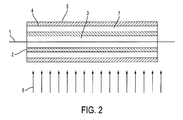
- Figures 1 and 2 show a cross-sectional view of a cylindrical embodiment of the curing apparatus of the present invention.
- a substrate or coated fiber 1 passes through the center line of a cure chamber apparatus.
- a UV transparent tube 2 Located concentrically around the fiber or substrate 1 is a UV transparent tube 2.
- the tube 2 is made from a material, such as quartz, that is transparent to UV radiation. This allows the UV radiation to pass through the tube 2 to the substrate 1, without interference or dissipation, thus ensuring that there is no drop in the efficiency of the curing process due to UV radiation being absorbed in the tube 2.
- the tube 2 is removable within the curing chamber assembly. This is because various volatiles and vapors are generated and emitted from the coating or substrate materials being cured during the curing process. These vapors and volatiles have tiny particles of impurities, which eventually become deposited on inner surface of the tube 2 during curing. These deposits build up and eventually adversely affect the efficiency of the curing process as they tend to block or further dissipate UV radiation directed towards the substrate or coating 1. Therefore, it is desirable that the tube 2 be easily removable allowing frequent replacement to ensure maximum efficiency of the curing apparatus. In Figures 1 and 2 the tube 2 is shown as a circular cylinder, however, the shape of the tube 2 can vary as required by the particular application of the apparatus (such as elliptical cylinder or oval cylinder).
- the passage of an inert gas through this space 3 serves two major purposes.
- the first purpose is to provide an inert environment which is free from oxygen around the substrate or fiber 1 being cured. If oxygen is present on or near the surface of the substrate or fiber 1 being cured, it will chemically react with the UV curable coatings or materials, thus limiting the desired efficiency of the polymerization (i.e. curing) of the coating materials. This is undesirable as it is necessary for the curing process to be as efficient as possible.
- the second purpose of the inert gas in the region 3 is to act as an exhaust vessel to blow out or remove as much of the volatiles and vapors emitted from the UV curable materials as possible.
- the presence of these vapors and volatiles in the space 3 around the substrate or fiber 1 tend to reduce the efficiency of the UV curing process, as they absorb and deflect some of the UV radiation directed at the substrate or fiber 1. Therefore, the inert gas is used to continuously move the vapors and volatiles out of the space 3 to increase the curing efficiency and decrease the deposition rate of the volatiles on the tube 2. By decreasing the deposition rate of the volatiles on the tube 2, the tube 2 will have to be replaced less frequently, thus increasing the efficiency of the curing apparatus while reducing costs.
- the inert gas which passes through the space 3 can be either pushed or drawn through the space 3 by any common or conventional method used to pass a gas through a tube.
- the inert gas passed through the space 3 can be either heated or chilled depending on the requirements of the curing process.
- the temperature of the substrate or fiber 1 and the space 3 surrounding the fiber or substrate 1 is often very critical in optimizing the curing or polymerization rate of the coating material being used.
- the optical fiber itself is very hot from the drawing process (which basically involves melting a glass preform and drawing it into a fiber).
- a chilled or cooled environment is provided within the space 3 the fiber and coating temperature can be brought down to an optimal temperature for polymerization of the coating. Without this temperature control the coating may become improperly cured because of the residual heat in the glass fiber.
- This accumulation of the fiber's residual heat with the curing heat causes thermally induced surface irregularities or material property gradients in the cured coating. Because of the importance of the coating in protecting the glass fibers, such irregularities in the coatings are extremely undesirable.
- the substrate 1 to be cured is for an optical fiber ribbon or cable (having a number of already coated and cured optical fibers affixed in a matrix or substrate) there is little or no residual heat, as is associated with the optical fiber drawing process.
- the fibers are usually at room temperature.
- Any common or conventional gas temperature control device can be used to regulate and control the temperature of the inert gas passing through the space 3. Further, in the preferred embodiment the inert gas can be either heated or chilled so as to allow the UV curing apparatus to be used in multiple applications.
- a tubular UV bulb 5 is located concentrically around the tube 2 such that a cooling region 7 is created between the inner surface 5A of the UV bulb 5 and the tube 2.
- the cooling region 7 is flooded with a UV transparent cooling medium that is both chilled and flowing.
- This cooling medium will allow substantial heat transfer from the bulb 5 into the cooling medium and cooling region 7 so as to ensure that the bulb 5 maintains a stable and efficient operating temperature. High temperatures can damage the bulb 5, the tube 2 and the coating or substrate 1 being passed through the apparatus.
- the cooling medium be UV transparent, such as chilled distilled water or chilled nitrogen gas, to ensure that the cooling medium does not absorb, refract or reflect any of the UV radiation emitted from the bulb 5 towards the substrate or fiber 1.
- the cooling medium is chilled nitrogen gas.
- any fluid medium that is transparent to the wavelength of light that is used to activate the photoinitiators or photosensitizers in the UV curable coatings or substrates 1 can be used. Chilled nitrogen gas is preferred because it is extremely UV transparent, it will aid in the extraction of heat from the UV bulb 5, it will provide an oxygen free environment between the bulb 5 and the tube 2, thus avoiding the creation of harmful ozone, and it is relatively inexpensive.
- any conventional or commonly used device or method can be used to flow the cooling medium through the cooling region 7.
- any common or conventional gas or liquid temperature control device can be used to regulate and control the temperature of the cooling medium as it passes through (or prior to it passing through) the cooling region 7.
- the temperature control of the bulb 5 is not as critical or is being handled by a different method, or when the heat generated by the bulb 5 is desirable.
- the flowing medium in the cooling region 7 is primarily used to remove oxygen from the environment between the bulb and the substrate (to eliminate the problems associated with the creation of ozone and depleting the UV energy available for curing the substrate).
- the bulb 5 is a tubular bulb which can be any cross-sectional shape that is most desirable for the fiber or substrate 1 to be cured.
- the shape of the bulb 5 is cylindrical.
- the fact that the bulb 5 is a tube ensures that there is a complete 360° exposure of the fiber or substrate 1 to the UV radiation emitted from the bulb 5. This will ensure efficient and even curing of the UV curable material.
- the UV bulb 5 contains elements which, when heated to a plasma by electric current or microwave radiation, radiate UV light in the optimal wavelength ranges required by the photoinitiators or photosensitizers used in the UV curable coatings of the fiber or substrate 1, typically between 250 nm and 450 nm.
- Excimer gases such as Xenon or Argon
- bulbs 5 of other types such as mercury bulbs, metal halide bulbs, or other bulbs containing any performance enhancing additives.
- the interior surface 5A of the bulb 5, or one or both of the surfaces 2A, 2B of the tube 2 are coated with an infrared (IR) filter (not shown).
- IR infrared
- all of the these surfaces 5A, 2A and 2B are coated with the IR filter.
- the infrared filter is of a type which is either completely, or mostly, transparent to UV radiation to allow the UV radiation to reach the substrate or fiber 1 to be cured, but reflects all, or most of, the other wavelengths of radiation, such as IR radiation back away from the substrate 1. This aspect of the present invention aids in directing non-UV radiation away from the substrate and back at the bulb 5 and the cooling fluid flow through the region 7.
- the shielding reflects wavelengths (IR) back into the bulb 5 which may then be used to increase the efficiency of activation of the plasma within the bulb 5, thus increasing the efficiency of the bulb's 5 output by requiring less energy input to maintain the plasma state.
- IR wavelengths
- the preferred embodiment of the present invention does not employ a standard reflector on the outer surface of the bulb 5, but instead uses a dichroic reflector 8.
- the dichroic reflector 8, of the present invention is transparent to most of the wavelengths transmitted by the bulb 5, but is reflective to the all, or most, of the UV radiation emitted by the bulb 5. Therefore, unlike the prior art, the IR radiation (heat) escapes through the outer surface of the bulb 5, while the UV radiation does not. This prevents the UV radiation from reacting with the oxygen in the air surrounding the exterior of the bulb 5, thus preventing the creation of harmful ozone, while allowing the heat generated by the bulb 5 to be emitted out of the outer surface of the bulb 5. This allows the bulb 5 to be cooled on its outer surface and its inner surface at the same time, greatly increasing temperature control of the bulb 5.
- the dichroic reflector 8 can either be a separate reflective surface positioned concentrically around the external surface of the bulb 5 (as shown in Figure 1), or can be a reflective coating placed on the exterior surface 5B of the bulb 5, similar to the filter coatings used on the tube 2 or the bulb 5. It should be noted however, that the dichroic reflector 8 is not necessary for every embodiment of the present invention, and the invention can operate without such a reflector.
- the preferred embodiment of the present invention employs the dichroic reflector 8 which is separate from the UV bulb 5, as shown in Figure 1.
- the dichroic reflector 8 has a plurality of holes or gaps (apertures) throughout its circumference to allow a cooling medium or fluid 6 (discussed in more detail below) to pass through the dichroic reflector 8 and cool the bulb 5.
- the dichroic reflector 8 has a solid surface (free of holes or apertures), and the cooling medium 6 flows in the gap between the reflector 8 and the bulb 5 in along the long axis of the apparatus, instead of across the apparatus as shown in Figures 1 and 2.
- the optimal cooling medium to be used in the region between the reflector 8 and the bulb 5 would be a liquid cooling medium, such as water.
- the cooling medium used in the space between the dichroic reflector 8 and the bulb 5 can be cooled by any commonly used or conventional means either prior to or while it is flowing through this space.
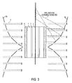
- the dichroic reflector 8a has a conical or beveled surface or surfaces in place of the cylindrical surface reflector 8 (shown in Figure 1).
- Figure 3 shows two opposite conical surfaces, however, the present invention is not limited to this configuration and may use a single conical surface reflector.
- some or all of the UV radiation emitted from the outer surface of the bulb 5B is reflected back at the center of the apparatus (i.e. the substrate 1) at an angle such that the reflected UV radiation contacts the surface of the substrate 1 just before entering the bulb cylinder 5 and/or just exiting the bulb 5, as shown in Figure 3.
- the intensity of this irradiation will be lower than that of the direct irradiation emitted from the bulb's inner surface 5A, but will still be concentric (360°) around the substrate 1 as long as the reflector surface 8a is designed and maintained properly.
- air, or other non-inert gas is used as the cooling medium 6 (discussed in more detail below)
- the resulting generation of ozone will deplete the UV energy available for the photopolymerization process.
- an inert gas for this cooling medium 6, however, the advantage gained by removing the UV energy dissipation associated with ozone generation is likely to be overwhelmed by the cost associated with using an inert gas.
- the high volume of flow required suggests that air would be the desirable fluid for the cooling medium 6, in this embodiment, and that the UV energy losses would be acceptable when considering the UV energy efficiency improvements gained elsewhere in this design.
- the cooling fluid or medium 6 is flowed past, or drawn by, the outer surface of the bulb 5 such that the cooling medium 6 acts as an additional heat sink absorbing heat from the bulb 5.
- the bulk of the cooling of the bulb 5 occurs on its exterior surface 5B, and not its interior surface 5A. This is, at least, partially due to the larger surface area on the exterior of the bulb 5 then the interior surface 5A of the bulb 5.
- the heat of the bulb 5 is primarily drawn outward instead of inward (heat flows from a high temperature region to a low temperature region at a rate proportional to the difference in the temperatures), heat will be drawn away from the substrate or coating 1 to be cured. This will be enhanced by chilling the cooling medium 6 either prior to or as it flows past the exterior surface of the bulb 5. If the medium 6 is chilled it creates an even larger temperature difference between the bulb 5 and the medium 6, increasing the heat transfer rate and drawing more heat away from the substrate 1.
- the bulb 5 is now effectively cooled by two cooling mediums, one internally in the region 7 and one externally by the cooling medium 6, the efficiency of the bulb 5 can be maintained more accurately, thus protecting the substrate or fiber 1 to be cured from undesirable high temperatures, while the longevity of the bulb 5 is increased.
- the dichroic reflector 8 or 8a reflects the majority, if not all, of the UV radiation back into the bulb 5, regular air can be used as the cooling medium 6.
- an oxygen free inert gas such as nitrogen
- air or other another non-inert gas
- the generation of ozone will result (but to a much lesser extent than if no reflector was used).
- the present invention will result in an increased curing efficiency of UV curable coatings and substrates for optical fiber production, while reducing the risks associated with over-curing the coatings, creation of harmful ozone and high levels of heat generated within the curing apparatus. Moreover, overall costs associated with the curing process will be reduced, while curing speeds can be increased, as less energy input will be required to reach required performance levels because of the increased curing efficiency and control.
- Figures 1 and 2 depict the UV curing apparatus as cylindrical or circular, it is possible for the apparatus to be of any shape.
- the tube 2, and bulb 5 can be elliptical or oval in shape so as to be used in conjunction with curing a flat optical fiber ribbon structure. Therefore, the cross-sectional shape of the apparatus (tube 2 and bulb 5) should not be limited to what is shown in the drawings and can be of any desirable shape for the purpose for which it is being used.
Landscapes
- Physics & Mathematics (AREA)
- Engineering & Computer Science (AREA)
- Life Sciences & Earth Sciences (AREA)
- Chemical & Material Sciences (AREA)
- Plasma & Fusion (AREA)
- Electromagnetism (AREA)
- Chemical Kinetics & Catalysis (AREA)
- General Life Sciences & Earth Sciences (AREA)
- Organic Chemistry (AREA)
- General Chemical & Material Sciences (AREA)
- Geochemistry & Mineralogy (AREA)
- Materials Engineering (AREA)
- Surface Treatment Of Glass Fibres Or Filaments (AREA)
- Optical Fibers, Optical Fiber Cores, And Optical Fiber Bundles (AREA)
Abstract
Description
Claims (56)
- An apparatus for curing an article passing through said apparatus through ultraviolet irradiation, comprising:a hollow tubular ultraviolet light emitting device (5) having an interior surface (5A) and an exterior surface (5B);an ultraviolet transparent tubular element (2) defining a first space (3) for insertion of an article (1) to be cured, said tubular element being surrounded by said ultraviolet light emitting device defining a second space (7) between an interior surface of said light emitting device and an outermost surface of said tubular element; andmeans for passing an inert gas through said first space.
- The apparatus according to claim 1, wherein the tubular ultraviolet light emitting device (5) is cylindrical.
- The apparatus according to claim 1 or 2, wherein the tubular element is removably connected to be easily removed and replaced.
- The apparatus according to claim 1, 2 or 3, further comprising a means to heat the inert gas passing through said first space.
- The apparatus according to claim 1, 2 or 3, further comprising a means to cool the inert gas passing through said first space.
- The apparatus according to claim 1, 2 or 3, further comprising a means to heat or cool the inert gas passing through said first space.
- The apparatus according to one of claims 1 to 6, wherein a surface of said tubular element (5) is coated with a first shielding layer, said first shielding layer being substantially transparent to ultraviolet light and reflective of infrared light emitted from said tubular ultraviolet light emitting device.
- The apparatus according to one of claims 1 to 6, wherein the interior surface (5A) of said tubular ultraviolet light emitting device (5) is coated with a shielding layer, said shielding layer being substantially transparent to ultraviolet light and reflective of infrared light emitted from said tubular ultraviolet light emitting device.
- The apparatus according to one of claims 1 to 8, further comprising a dichroic reflector (8) surrounding the exterior surface of said tubular ultraviolet light emitting device, said dichroic reflector reflecting ultraviolet light emitted from said tubular ultraviolet light emitting device.
- The apparatus according to one of claims 1 to 9, further comprising a means for flowing a first cooling medium through said second space (7).
- The apparatus according to claim 10, wherein said first cooling medium is transparent to ultraviolet radiation.
- The apparatus according to claim 10 or 11, wherein said first cooling medium is a gas.
- The apparatus according to claim 10 or 11, wherein said first cooling medium is a liquid.
- The apparatus according to one of claims 1 to 13, further comprising a means to flow a second cooling medium past the exterior surface (5B) of said tubular ultraviolet light emitting device (5).
- The apparatus according to one of claims 9 to 14, further comprising a means to flow a second cooling medium past an exterior surface of said dichroic reflector (8).
- The apparatus according to claim 15, wherein said dichroic reflector has a plurality of apertures for allowing said second cooling medium to contact the exterior surface of said tubular ultraviolet light emitting device (5).
- The apparatus according to claim 14, 15 or 16, wherein said second cooling medium is air.
- The apparatus according to one of claims 9 to 13, further comprising a third space defined between said dichroic reflector (8) and said tubular ultraviolet light emitting device (5).
- The apparatus according to claim 18, further comprising a means for passing a second cooling medium through said third space.
- The apparatus according to claim 19, wherein said second cooling medium is a liquid.
- The apparatus according to one of claims 9 to 20, wherein said dichroic reflector (8) reflects at least some ultraviolet radiation emitted from the exterior surface of said tubular ultraviolet light emitting device (5) such that said some ultraviolet radiation contacts the surface of an article to be cured prior to said article entering said tubular ultraviolet light emitting device.
- The apparatus according to one of claims 9 to 20, wherein said dichroic reflector (8) reflects at least some ultraviolet radiation emitted from the exterior surface of said tubular ultraviolet light emitting device (5) such that said some ultraviolet radiation contacts the surface of an article to be cured after said article exits said tubular ultraviolet light emitting device.
- The apparatus according to one of claims 9 to 20, wherein said dichroic reflector (8) reflects at least some ultraviolet radiation emitted from the exterior surface of said tubular ultraviolet light emitting device (5) such that said some ultraviolet radiation contacts the surface of an article to be cured prior to said article entering said tubular ultraviolet light emitting device and after said article exits said tubular ultraviolet light emitting device.
- An apparatus for curing an article inserted in said apparatus through ultraviolet irradiation comprising:a hollow tubular ultraviolet light emitting device (5) having an interior surface (5A) and an exterior surface (5B);a dichroic reflector (8) surrounding said light emitting device, said dichroic reflector reflecting only ultraviolet light;an ultraviolet transparent tubular element (2) defining a first space (3) for insertion of an article (1) to be cured, said tubular element being surrounded by said ultraviolet light emitting device with a second space (7) provided between the interior surface of said ultraviolet light emitting device and said tubular element.
- The apparatus according to claim 24, further comprising a means for passing an inert gas through said first space.
- The apparatus according to claim 25, further comprising a means to cool or heat said inert gas passing through said first space.
- The apparatus according to one of claims 24 to 26, wherein a surface of said tubular element (2) is coated with a first shielding layer, said first shielding layer being substantially transparent to ultraviolet light and reflective of infrared light emitted from said tubular ultraviolet light emitting device.
- The apparatus according to claim 24, 25 or 26, wherein the interior surface of said tubular ultraviolet light emitting device is coated with a shielding layer, said shielding layer being substantially transparent to ultraviolet light and reflective of infrared light emitted from said tubular ultraviolet light emitting device.
- The apparatus according to one of claims 24 to 28, wherein the tubular element (2) is removably connected so as to be easily removed and replaced.
- The apparatus according to one of claims 24 to 29, further comprising a means for flowing a first cooling medium through said second space (7).
- The apparatus according to claim 30, wherein said first cooling medium is transparent to ultraviolet radiation.
- The apparatus according to claim 30 or 31, wherein said first cooling medium is a gas.
- The apparatus according to claim 30 or 31, wherein said first cooling medium is a liquid.
- The apparatus according to one of claims 24 to 33, further comprising a means to flow a second cooling medium past an exterior surface of said dichroic reflector (8).
- The apparatus according to claim 34, wherein said dichroic reflector has a plurality of apertures for allowing said second cooling medium to contact the exterior surface (5B) of said tubular ultraviolet light emitting device.
- The apparatus according to claim 34 or 35, wherein said second cooling medium is air.
- The apparatus according to one of claims 24 to 33, further comprising a third space defined between said dichroic reflector (8) and said tubular ultraviolet light emitting device (5).
- The apparatus according to claim 37, further comprising a means for passing a second cooling medium through said third space.
- The apparatus according to claim 38, wherein said second cooling medium is a liquid.
- The apparatus according to one of claims 24 to 39, wherein said dichroic reflector (8) reflects at least some ultraviolet radiation emitted from the exterior surface of said tubular ultraviolet light emitting device (5) such that said some ultraviolet radiation contacts the surface of an article to be cured prior to said article entering said tubular ultraviolet light emitting device.
- The apparatus according to one of claims 24 to 39, wherein said dichroic reflector (8) reflects at least some ultraviolet radiation emitted from the exterior surface of said tubular ultraviolet light emitting device (5) such that said some ultraviolet radiation contacts the surface of an article to be cured after said article exits said tubular ultraviolet light emitting device.
- The apparatus according to one of claims 24 to 39, wherein said dichroic reflector (8) reflects at least some ultraviolet radiation emitted from the exterior surface of said tubular ultraviolet light emitting device (5) such that said some ultraviolet radiation contacts the surface of an article to be cured prior to said article entering said tubular ultraviolet light emitting device and after said article exits said tubular ultraviolet light emitting device.
- A method for curing an article passing through a curing apparatus with ultraviolet radiation, comprising:passing an article (1) to be cured through a first space (3) defined by an ultraviolet transparent tubular element (2);flowing an inert gas through said first space (3);emitting ultraviolet light from a hollow tubular ultraviolet light emitting device (5) having an interior surface (5A) and an exterior surface (5B), said tubular ultraviolet light device surrounds said tubular element defining a second space (7) between the interior surface of said ultraviolet light emitting device and an outermost surface of said tubular element;exposing said article to be cured to said ultraviolet light; andflowing a first cooling medium through said second space.
- The method according to claim 43, further comprising cooling or heating said inert gas flowing through said first space.
- The method according to claim 43 or 44, wherein said first cooling medium is an ultraviolet transparent gas or liquid.
- The method according to claim 43, 44 or 45, further comprising cooling said first cooling medium flowing through said second space.
- The method according to one of claims 43 to 46, further comprising flowing a second cooling medium past the exterior surface of said ultraviolet light emitting device (5).
- The method according to one of claims 43 to 47, further comprising reflecting infrared radiation emitted from said tubular ultraviolet light emitting device off of a surface of said tubular element (2).
- The method according to one of claims 43 to 48, further comprising reflecting infrared radiation emitted from said tubular ultraviolet light emitting device off of the interior surface of said ultraviolet light emitting device.
- The method according to one of claims 43 to 49, further comprising reflecting ultraviolet radiation off of a dichroic reflector (8) surrounding the exterior surface of said ultraviolet light emitting device (5).
- The method according to claim 50, further comprising flowing a second cooling medium over an exterior surface of said dichroic reflector.
- The method according to claim 50, further comprising flowing a second cooling medium through a plurality of apertures in said dichroic reflector so said second cooling medium contacts the exterior surface of said ultraviolet light emitting device.
- The method according to claim 50, further comprising flowing a second cooling medium through a third space defined between said dichroic reflector and said ultraviolet light emitting device.
- The method according to one of claims 50 to 53 , further comprising reflecting at least some ultraviolet radiation emitted from the exterior surface of said tubular ultraviolet light emitting device (5) off of said dichroic reflector (8) such that said some ultraviolet radiation contacts the surface of the article (1) to be cured prior to said article entering said tubular ultraviolet light emitting device.
- The apparatus according to one of claims 50 to 53, further comprising reflecting at least some ultraviolet radiation emitted from the exterior surface of said tubular ultraviolet light emitting device (5) off of said dichroic reflector (8) such that said some ultraviolet radiation contacts the surface of the article (1) to be cured after said article exits said tubular ultraviolet light emitting device.
- The apparatus according to one of claims 50 to 53, further comprising reflecting at least some ultraviolet radiation emitted from the exterior surface of said tubular ultraviolet light emitting device (5) off of said dichroic reflector (8) such that said some ultraviolet radiation contacts the surface of the article (1) to be cured prior to said article entering said tubular ultraviolet light emitting device and after said article exits said tubular ultraviolet light emitting device.
Applications Claiming Priority (2)
| Application Number | Priority Date | Filing Date | Title |
|---|---|---|---|
| US09/739,670 US6759664B2 (en) | 2000-12-20 | 2000-12-20 | Ultraviolet curing system and bulb |
| US739670 | 2000-12-20 |
Publications (2)
| Publication Number | Publication Date |
|---|---|
| EP1216968A1 true EP1216968A1 (en) | 2002-06-26 |
| EP1216968B1 EP1216968B1 (en) | 2012-04-18 |
Family
ID=24973308
Family Applications (1)
| Application Number | Title | Priority Date | Filing Date |
|---|---|---|---|
| EP01403108A Expired - Lifetime EP1216968B1 (en) | 2000-12-20 | 2001-12-04 | Method and apparatus for ultraviolet curing |
Country Status (3)
| Country | Link |
|---|---|
| US (1) | US6759664B2 (en) |
| EP (1) | EP1216968B1 (en) |
| AT (1) | ATE554057T1 (en) |
Cited By (1)
| Publication number | Priority date | Publication date | Assignee | Title |
|---|---|---|---|---|
| US6759664B2 (en) * | 2000-12-20 | 2004-07-06 | Alcatel | Ultraviolet curing system and bulb |
Families Citing this family (25)
| Publication number | Priority date | Publication date | Assignee | Title |
|---|---|---|---|---|
| EP2009676B8 (en) | 2002-05-08 | 2012-11-21 | Phoseon Technology, Inc. | A semiconductor materials inspection system |
| US6852191B2 (en) * | 2002-08-01 | 2005-02-08 | Equipements De Transformation Imac | Method and apparatus for manufacturing pressure sensitive adhesive label stocks with printing under adhesive and product produced thereby |
| DE10346131A1 (en) * | 2003-10-01 | 2005-05-12 | Heraeus Noblelight Gmbh | UV lamp assembly and its use |
| KR101288758B1 (en) | 2004-12-30 | 2013-07-23 | 포세온 테크날러지 인코퍼레이티드 | Methods and systems relating to light sources for use in industrial processes |
| US8029637B2 (en) * | 2007-11-29 | 2011-10-04 | Hitachi Global Technologies Netherlands, B.V. | System, method and apparatus for ultraviolet curing of adhesives with light beam shaping in disk drive manufacturing |
| US8022377B2 (en) * | 2008-04-22 | 2011-09-20 | Applied Materials, Inc. | Method and apparatus for excimer curing |
| US7923706B2 (en) * | 2008-10-03 | 2011-04-12 | Nordson Corporation | Ultraviolet curing apparatus for continuous material |
| US7964858B2 (en) | 2008-10-21 | 2011-06-21 | Applied Materials, Inc. | Ultraviolet reflector with coolant gas holes and method |
| US9093258B2 (en) | 2011-06-08 | 2015-07-28 | Xenex Disinfection Services, Llc | Ultraviolet discharge lamp apparatuses having optical filters which attenuate visible light |
| US9165756B2 (en) * | 2011-06-08 | 2015-10-20 | Xenex Disinfection Services, Llc | Ultraviolet discharge lamp apparatuses with one or more reflectors |
| US8445864B2 (en) * | 2011-08-26 | 2013-05-21 | Raytheon Company | Method and apparatus for anti-biofouling of a protected surface in liquid environments |
| WO2013055772A1 (en) | 2011-10-12 | 2013-04-18 | Phoseon Technology, Inc. | Multiple light collection and lens combinations with co-located foci for curing optical fibers |
| US9114182B2 (en) | 2012-02-28 | 2015-08-25 | Xenex Disinfection Services, Llc | Germicidal systems and apparatuses having hollow tumbling chambers |
| CA2931403C (en) | 2012-12-06 | 2020-03-31 | Xenex Disinfection Services, Llc. | Systems which determine operating parameters and disinfection schedules for germicidal devices and germicidal lamp apparatuses including lens systems |
| US8816301B2 (en) | 2012-12-07 | 2014-08-26 | Xenex Healthcare Services, Llc | Lamp and reflector arrangements for apparatuses with multiple germicidal lamps |
| US9776219B2 (en) | 2013-01-17 | 2017-10-03 | Raytheon Company | Method and apparatus for removing biofouling from a protected surface in a liquid environment |
| US9867894B2 (en) | 2015-07-02 | 2018-01-16 | Xenex Disinfection Services, Llc. | Germicidal apparatuses with configurations to selectively conduct different disinfection modes interior and exterior to the apparatus |
| US9517284B1 (en) | 2015-07-02 | 2016-12-13 | Xenex Disinfection Services, Llc. | Germicidal apparatuses with configurations to selectively conduct different disinfection modes interior and exterior to the apparatus |
| WO2016131069A2 (en) * | 2015-12-11 | 2016-08-18 | Johnson Kenneth Carlisle | Euv light source with spectral purity filter and power recycling |
| US10328174B2 (en) | 2017-08-31 | 2019-06-25 | Radiant Industrial Solutions, LLC | Portable microorganism sanitation system |
| US11672898B2 (en) * | 2018-06-08 | 2023-06-13 | Oregon State University | Microfluidic removal of excess bilirubin from blood |
| CN109848016A (en) * | 2019-01-31 | 2019-06-07 | 南京新趋势光电有限公司 | For the cured ultraviolet irradiation device of cable |
| US12140813B2 (en) * | 2019-11-05 | 2024-11-12 | Ofs Fitel, Llc | Low-attenuation rollable optical fiber ribbon |
| RU205117U1 (en) * | 2020-12-25 | 2021-06-28 | Федеральное государственное бюджетное учреждение науки Институт сильноточной электроники Сибирского отделения Российской академии наук, (ИСЭ СО РАН) | Radiation source |
| CN116803547B (en) * | 2023-06-27 | 2024-11-19 | 深圳劲嘉集团股份有限公司 | Multi-wavelength coupled UV curing equipment |
Citations (3)
| Publication number | Priority date | Publication date | Assignee | Title |
|---|---|---|---|---|
| JPS6158840A (en) * | 1984-08-29 | 1986-03-26 | Furukawa Electric Co Ltd:The | Curing device for clad layer of optical fiber |
| DE3913519A1 (en) * | 1989-04-25 | 1990-10-31 | Rheydt Kabelwerk Ag | Rapid UV hardening system - for plastics coating on optical fibre |
| EP1088638A2 (en) * | 1999-09-28 | 2001-04-04 | Alcatel | An apparatus and method for curing a photocurable coating provided on a fiber |
Family Cites Families (20)
| Publication number | Priority date | Publication date | Assignee | Title |
|---|---|---|---|---|
| US3926556A (en) * | 1973-05-30 | 1975-12-16 | Raymond Marcel Gut Boucher | Biocidal electromagnetic synergistic process |
| US4100418A (en) * | 1977-03-04 | 1978-07-11 | Gene D. Hoffman | Method of and means for filtering the infrared rays from a source of UV radiation |
| US4636405A (en) * | 1985-12-24 | 1987-01-13 | Corning Glass Works | Curing apparatus for coated fiber |
| US5173638A (en) * | 1986-07-22 | 1992-12-22 | Bbc Brown, Boveri Ag | High-power radiator |
| CH670171A5 (en) * | 1986-07-22 | 1989-05-12 | Bbc Brown Boveri & Cie | |
| AU616589B2 (en) * | 1989-01-30 | 1991-10-31 | Lumenyte International Corporation | Improved linear optical conduits, systems and methods of manufacture |
| US5067831A (en) * | 1989-12-13 | 1991-11-26 | Lumenyte International Corporation | Linear optical conduits |
| MY108087A (en) * | 1989-07-12 | 1996-08-15 | Randy L Stinson | Apparatus and method for irradiating cells. |
| US5150705A (en) * | 1989-07-12 | 1992-09-29 | Stinson Randy L | Apparatus and method for irradiating cells |
| JP2567506Y2 (en) | 1992-02-13 | 1998-04-02 | 東北沖電気株式会社 | Wire dot print head |
| EP0607960B2 (en) * | 1993-01-20 | 2001-05-16 | Ushiodenki Kabushiki Kaisha | Dielectric barrier discharge lamp |
| TW324106B (en) * | 1993-09-08 | 1998-01-01 | Ushio Electric Inc | Dielectric barrier layer discharge lamp |
| DE59409236D1 (en) | 1994-08-15 | 2000-04-27 | Sulzer Chemtech Ag Winterthur | Device for treating fluids with UV radiation |
| FR2725797B1 (en) | 1994-10-13 | 1997-01-03 | Alcatel Cable | PROCESS FOR COATING A TAPE OF OPTICAL FIBERS BY MEANS OF A RESIN, AND DEVICE FOR IMPLEMENTING SUCH A PROCESS |
| FR2729152A1 (en) | 1995-01-06 | 1996-07-12 | Alcatel Cable | UV CROSSLINKING DEVICE |
| US5827611A (en) * | 1997-03-10 | 1998-10-27 | Hoechst Celanese Corp | Multilayered thermoplastic article with special properties |
| US6419749B1 (en) * | 1999-11-05 | 2002-07-16 | Fusion Uv Systems, Inc. | Apparatus for UV curing a coating on a filament or the like and method of manufacturing |
| US6351070B1 (en) * | 1999-12-28 | 2002-02-26 | Fusion Uv Systems, Inc. | Lamp with self-constricting plasma light source |
| US6626561B2 (en) * | 2000-06-22 | 2003-09-30 | Fusion Uv Systems, Inc. | Lamp structure, having elliptical reflectors, for uniformly irradiating surfaces of optical fiber and method of use thereof |
| US6759664B2 (en) * | 2000-12-20 | 2004-07-06 | Alcatel | Ultraviolet curing system and bulb |
-
2000
- 2000-12-20 US US09/739,670 patent/US6759664B2/en not_active Expired - Fee Related
-
2001
- 2001-12-04 EP EP01403108A patent/EP1216968B1/en not_active Expired - Lifetime
- 2001-12-04 AT AT01403108T patent/ATE554057T1/en active
Patent Citations (4)
| Publication number | Priority date | Publication date | Assignee | Title |
|---|---|---|---|---|
| JPS6158840A (en) * | 1984-08-29 | 1986-03-26 | Furukawa Electric Co Ltd:The | Curing device for clad layer of optical fiber |
| DE3913519A1 (en) * | 1989-04-25 | 1990-10-31 | Rheydt Kabelwerk Ag | Rapid UV hardening system - for plastics coating on optical fibre |
| DE3913519C2 (en) | 1989-04-25 | 1996-06-27 | Rheydt Kabelwerk Ag | UV curing system for optical fibers |
| EP1088638A2 (en) * | 1999-09-28 | 2001-04-04 | Alcatel | An apparatus and method for curing a photocurable coating provided on a fiber |
Non-Patent Citations (1)
| Title |
|---|
| PATENT ABSTRACTS OF JAPAN vol. 010, no. 226 (C - 364) 7 August 1986 (1986-08-07) * |
Cited By (1)
| Publication number | Priority date | Publication date | Assignee | Title |
|---|---|---|---|---|
| US6759664B2 (en) * | 2000-12-20 | 2004-07-06 | Alcatel | Ultraviolet curing system and bulb |
Also Published As
| Publication number | Publication date |
|---|---|
| EP1216968B1 (en) | 2012-04-18 |
| US6759664B2 (en) | 2004-07-06 |
| US20040061079A1 (en) | 2004-04-01 |
| ATE554057T1 (en) | 2012-05-15 |
Similar Documents
| Publication | Publication Date | Title |
|---|---|---|
| US6759664B2 (en) | Ultraviolet curing system and bulb | |
| JP6605464B2 (en) | Curing apparatus, photoreactive system, and method | |
| CN102792464B (en) | For the UV LED base lamp of compact UV cure lamp assembly | |
| CN103827718B (en) | The double-elliptic reflective device with common location focus for curing optical fiber | |
| EP3168201B1 (en) | Intensity adjustable uv curing equipment for optical fiber coating | |
| JP6017573B2 (en) | Multiple light collection and lens combination with co-located focus for curing optical fibers | |
| US4636405A (en) | Curing apparatus for coated fiber | |
| US4591724A (en) | Curing apparatus | |
| CN103319100B (en) | Ultraviolet curing equipment and method for optical fiber coating | |
| KR20110128151A (en) | Curing device adopting angled LED | |
| WO2002100531A1 (en) | Uv curing system for heat sensitive substances | |
| JPH06144881A (en) | Curing device for coating agent applied on optical fiber | |
| JPH0586338B2 (en) | ||
| JPS63213830A (en) | Ultraviolet-ray irradiating device |
Legal Events
| Date | Code | Title | Description |
|---|---|---|---|
| PUAI | Public reference made under article 153(3) epc to a published international application that has entered the european phase |
Free format text: ORIGINAL CODE: 0009012 |
|
| AK | Designated contracting states |
Kind code of ref document: A1 Designated state(s): AT BE CH CY DE DK ES FI FR GB GR IE IT LI LU MC NL PT SE TR |
|
| AX | Request for extension of the european patent |
Free format text: AL;LT;LV;MK;RO;SI |
|
| 17P | Request for examination filed |
Effective date: 20021202 |
|
| AKX | Designation fees paid |
Designated state(s): AT BE CH CY DE DK ES FI FR GB GR IE IT LI LU MC NL PT SE TR |
|
| 17Q | First examination report despatched |
Effective date: 20031009 |
|
| RAP1 | Party data changed (applicant data changed or rights of an application transferred) |
Owner name: DRAKA COMTEQ B.V. |
|
| RAP1 | Party data changed (applicant data changed or rights of an application transferred) |
Owner name: DRAKA COMTEQ B.V. |
|
| RAP1 | Party data changed (applicant data changed or rights of an application transferred) |
Owner name: DRAKA COMTEQ B.V. |
|
| GRAP | Despatch of communication of intention to grant a patent |
Free format text: ORIGINAL CODE: EPIDOSNIGR1 |
|
| GRAS | Grant fee paid |
Free format text: ORIGINAL CODE: EPIDOSNIGR3 |
|
| GRAA | (expected) grant |
Free format text: ORIGINAL CODE: 0009210 |
|
| AK | Designated contracting states |
Kind code of ref document: B1 Designated state(s): AT BE CH CY DE DK ES FI FR GB GR IE IT LI LU MC NL PT SE TR |
|
| REG | Reference to a national code |
Ref country code: GB Ref legal event code: FG4D |
|
| REG | Reference to a national code |
Ref country code: CH Ref legal event code: EP |
|
| REG | Reference to a national code |
Ref country code: IE Ref legal event code: FG4D |
|
| REG | Reference to a national code |
Ref country code: AT Ref legal event code: REF Ref document number: 554057 Country of ref document: AT Kind code of ref document: T Effective date: 20120515 |
|
| REG | Reference to a national code |
Ref country code: DE Ref legal event code: R096 Ref document number: 60146423 Country of ref document: DE Effective date: 20120614 |
|
| REG | Reference to a national code |
Ref country code: NL Ref legal event code: VDEP Effective date: 20120418 |
|
| REG | Reference to a national code |
Ref country code: AT Ref legal event code: MK05 Ref document number: 554057 Country of ref document: AT Kind code of ref document: T Effective date: 20120418 |
|
| PG25 | Lapsed in a contracting state [announced via postgrant information from national office to epo] |
Ref country code: FI Free format text: LAPSE BECAUSE OF FAILURE TO SUBMIT A TRANSLATION OF THE DESCRIPTION OR TO PAY THE FEE WITHIN THE PRESCRIBED TIME-LIMIT Effective date: 20120418 Ref country code: SE Free format text: LAPSE BECAUSE OF FAILURE TO SUBMIT A TRANSLATION OF THE DESCRIPTION OR TO PAY THE FEE WITHIN THE PRESCRIBED TIME-LIMIT Effective date: 20120418 Ref country code: CY Free format text: LAPSE BECAUSE OF FAILURE TO SUBMIT A TRANSLATION OF THE DESCRIPTION OR TO PAY THE FEE WITHIN THE PRESCRIBED TIME-LIMIT Effective date: 20120418 |
|
| PG25 | Lapsed in a contracting state [announced via postgrant information from national office to epo] |
Ref country code: GR Free format text: LAPSE BECAUSE OF FAILURE TO SUBMIT A TRANSLATION OF THE DESCRIPTION OR TO PAY THE FEE WITHIN THE PRESCRIBED TIME-LIMIT Effective date: 20120719 Ref country code: PT Free format text: LAPSE BECAUSE OF FAILURE TO SUBMIT A TRANSLATION OF THE DESCRIPTION OR TO PAY THE FEE WITHIN THE PRESCRIBED TIME-LIMIT Effective date: 20120820 |
|
| PG25 | Lapsed in a contracting state [announced via postgrant information from national office to epo] |
Ref country code: BE Free format text: LAPSE BECAUSE OF FAILURE TO SUBMIT A TRANSLATION OF THE DESCRIPTION OR TO PAY THE FEE WITHIN THE PRESCRIBED TIME-LIMIT Effective date: 20120418 |
|
| PG25 | Lapsed in a contracting state [announced via postgrant information from national office to epo] |
Ref country code: DK Free format text: LAPSE BECAUSE OF FAILURE TO SUBMIT A TRANSLATION OF THE DESCRIPTION OR TO PAY THE FEE WITHIN THE PRESCRIBED TIME-LIMIT Effective date: 20120418 Ref country code: AT Free format text: LAPSE BECAUSE OF FAILURE TO SUBMIT A TRANSLATION OF THE DESCRIPTION OR TO PAY THE FEE WITHIN THE PRESCRIBED TIME-LIMIT Effective date: 20120418 Ref country code: NL Free format text: LAPSE BECAUSE OF FAILURE TO SUBMIT A TRANSLATION OF THE DESCRIPTION OR TO PAY THE FEE WITHIN THE PRESCRIBED TIME-LIMIT Effective date: 20120418 |
|
| PLBE | No opposition filed within time limit |
Free format text: ORIGINAL CODE: 0009261 |
|
| STAA | Information on the status of an ep patent application or granted ep patent |
Free format text: STATUS: NO OPPOSITION FILED WITHIN TIME LIMIT |
|
| PG25 | Lapsed in a contracting state [announced via postgrant information from national office to epo] |
Ref country code: IT Free format text: LAPSE BECAUSE OF FAILURE TO SUBMIT A TRANSLATION OF THE DESCRIPTION OR TO PAY THE FEE WITHIN THE PRESCRIBED TIME-LIMIT Effective date: 20120418 |
|
| 26N | No opposition filed |
Effective date: 20130121 |
|
| PG25 | Lapsed in a contracting state [announced via postgrant information from national office to epo] |
Ref country code: ES Free format text: LAPSE BECAUSE OF FAILURE TO SUBMIT A TRANSLATION OF THE DESCRIPTION OR TO PAY THE FEE WITHIN THE PRESCRIBED TIME-LIMIT Effective date: 20120729 |
|
| REG | Reference to a national code |
Ref country code: DE Ref legal event code: R097 Ref document number: 60146423 Country of ref document: DE Effective date: 20130121 |
|
| PG25 | Lapsed in a contracting state [announced via postgrant information from national office to epo] |
Ref country code: MC Free format text: LAPSE BECAUSE OF NON-PAYMENT OF DUE FEES Effective date: 20121231 |
|
| REG | Reference to a national code |
Ref country code: CH Ref legal event code: PL |
|
| REG | Reference to a national code |
Ref country code: IE Ref legal event code: MM4A |
|
| PG25 | Lapsed in a contracting state [announced via postgrant information from national office to epo] |
Ref country code: LI Free format text: LAPSE BECAUSE OF NON-PAYMENT OF DUE FEES Effective date: 20121231 Ref country code: IE Free format text: LAPSE BECAUSE OF NON-PAYMENT OF DUE FEES Effective date: 20121204 Ref country code: CH Free format text: LAPSE BECAUSE OF NON-PAYMENT OF DUE FEES Effective date: 20121231 |
|
| PGFP | Annual fee paid to national office [announced via postgrant information from national office to epo] |
Ref country code: DE Payment date: 20131220 Year of fee payment: 13 Ref country code: GB Payment date: 20131219 Year of fee payment: 13 |
|
| PG25 | Lapsed in a contracting state [announced via postgrant information from national office to epo] |
Ref country code: TR Free format text: LAPSE BECAUSE OF FAILURE TO SUBMIT A TRANSLATION OF THE DESCRIPTION OR TO PAY THE FEE WITHIN THE PRESCRIBED TIME-LIMIT Effective date: 20120418 |
|
| PG25 | Lapsed in a contracting state [announced via postgrant information from national office to epo] |
Ref country code: LU Free format text: LAPSE BECAUSE OF NON-PAYMENT OF DUE FEES Effective date: 20121204 |
|
| PGFP | Annual fee paid to national office [announced via postgrant information from national office to epo] |
Ref country code: FR Payment date: 20131220 Year of fee payment: 13 |
|
| REG | Reference to a national code |
Ref country code: DE Ref legal event code: R119 Ref document number: 60146423 Country of ref document: DE |
|
| GBPC | Gb: european patent ceased through non-payment of renewal fee |
Effective date: 20141204 |
|
| REG | Reference to a national code |
Ref country code: FR Ref legal event code: ST Effective date: 20150831 |
|
| PG25 | Lapsed in a contracting state [announced via postgrant information from national office to epo] |
Ref country code: GB Free format text: LAPSE BECAUSE OF NON-PAYMENT OF DUE FEES Effective date: 20141204 Ref country code: DE Free format text: LAPSE BECAUSE OF NON-PAYMENT OF DUE FEES Effective date: 20150701 |
|
| PG25 | Lapsed in a contracting state [announced via postgrant information from national office to epo] |
Ref country code: FR Free format text: LAPSE BECAUSE OF NON-PAYMENT OF DUE FEES Effective date: 20141231 |