EP1216945A2 - Device for braking rolls, especially paper rolls - Google Patents
Device for braking rolls, especially paper rolls Download PDFInfo
- Publication number
- EP1216945A2 EP1216945A2 EP01129226A EP01129226A EP1216945A2 EP 1216945 A2 EP1216945 A2 EP 1216945A2 EP 01129226 A EP01129226 A EP 01129226A EP 01129226 A EP01129226 A EP 01129226A EP 1216945 A2 EP1216945 A2 EP 1216945A2
- Authority
- EP
- European Patent Office
- Prior art keywords
- cushion
- runway
- roll
- chamber
- roller
- Prior art date
- Legal status (The legal status is an assumption and is not a legal conclusion. Google has not performed a legal analysis and makes no representation as to the accuracy of the status listed.)
- Withdrawn
Links
Images


Classifications
-
- B—PERFORMING OPERATIONS; TRANSPORTING
- B65—CONVEYING; PACKING; STORING; HANDLING THIN OR FILAMENTARY MATERIAL
- B65H—HANDLING THIN OR FILAMENTARY MATERIAL, e.g. SHEETS, WEBS, CABLES
- B65H23/00—Registering, tensioning, smoothing or guiding webs
- B65H23/04—Registering, tensioning, smoothing or guiding webs longitudinally
- B65H23/06—Registering, tensioning, smoothing or guiding webs longitudinally by retarding devices, e.g. acting on web-roll spindle
- B65H23/08—Registering, tensioning, smoothing or guiding webs longitudinally by retarding devices, e.g. acting on web-roll spindle acting on web roll being unwound
-
- B—PERFORMING OPERATIONS; TRANSPORTING
- B65—CONVEYING; PACKING; STORING; HANDLING THIN OR FILAMENTARY MATERIAL
- B65H—HANDLING THIN OR FILAMENTARY MATERIAL, e.g. SHEETS, WEBS, CABLES
- B65H2301/00—Handling processes for sheets or webs
- B65H2301/40—Type of handling process
- B65H2301/41—Winding, unwinding
- B65H2301/413—Supporting web roll
- B65H2301/4137—Supporting web roll on its outer circumference
-
- B—PERFORMING OPERATIONS; TRANSPORTING
- B65—CONVEYING; PACKING; STORING; HANDLING THIN OR FILAMENTARY MATERIAL
- B65H—HANDLING THIN OR FILAMENTARY MATERIAL, e.g. SHEETS, WEBS, CABLES
- B65H2301/00—Handling processes for sheets or webs
- B65H2301/40—Type of handling process
- B65H2301/41—Winding, unwinding
- B65H2301/414—Winding
- B65H2301/4148—Winding slitting
Definitions
- the invention relates to a device for braking on rolls rolling off a runway, in particular paper rolls, with a pillow that contains a fluid and by exposure a role against the resistance of the fluid is deformable.
- paper mills there are paper webs that are up to ten meters can be wide, cut to widths requested by customers and rolled up into rolls of the desired diameter. Such rolls typically have a width of 200 mm up to 4,000 mm and diameters from 500 mm to 1,500 mm.
- slitter which are stopped and unloaded as soon as one Litter roles has arisen.
- slitter rewinder There are two different types known from slitter rewinder, namely those with double support rollers and those with single carrier rollers. With slitter rewinder with double carrier rollers, all the resulting rolls of supported by two parallel rollers; all have roles a common geometric axis at all times.
- EP-A-0 705 783 is a device of the type described in the opening paragraph Genus known for braking paper rolls has at least one lever for each of them.
- This lever has a transverse to it at one of its two ends
- Each of these Lever is articulated with a handlebar in its central area connected in an area adjacent to the cross conveyor the pit around one parallel to the first journal stationary second pivot pin is pivotable and on an air cushion in the form of a bellows supports that he the associated lever up in a Brake position is urgent when the bellows is filled with compressed air is.
- From DE-A-33 29 066 is a coil removal device for a automatic winding machine known for stopping Coils on an inclined runway towards one Cross conveyors roll, a storage rail parallel to the spool axis by operating a cylinder either in one Position in which it stands in the way of the coil and in a raised position Position is pivotable in which the coil Releases path to cross conveyor.
- a railing-like Guide rail attached so that it spools serves as a stop and prevents them from crossing the cross conveyor to roll away.
- the invention has for its object a device to create the genus described at the beginning, which with particular simple means a more gentle braking of rollers, especially paper rolls.
- Fig.1 is a slitter 10 of known type with two support rollers 12 shown in parallel to each other axes of rotation arranged in a common horizontal plane have, and the longitudinal knife 14 for dividing a wide Paper web 16 are connected upstream.
- the longitudinal knife 14 are like Usually designed as cutting rollers, parallel to the axes the support rollers 12 adjustable and removable and by additional same longitudinal knife can be added, so that they the wide paper web 16 in a more or less large number able to cut individual paper webs 18.
- the single ones Paper webs 18 are each on the support rollers 12 Roll 20 wound and then, for example by lowering the support rollers 12, delivered to a runway 22, which is symbolized by an arrow and 1 to 2% gradient in the direction away from the slitter 10.
- a slitter 10 is also known Design shown that has only a single support roller 12 and again with longitudinal knives 14 for dividing one wide paper web 16 into individual paper webs 18 is.
- the individual paper webs 18 each a roll 20 wound, but each roll one
- a pair of bearing journals, not shown, which engage on their end faces is assigned such that the rollers 20 alternately to one and the other side of the support roller 12 against each other are staggered.
- closes on both sides of the roll cutter 10 each have a runway 22 which again a gradient of 1 to 2% in the direction of the slitter away.
- Each of the ramps 24 and 26 shown in Figure 3 has a slope, the opposite of that of the runway 22 and is larger in amount. At least the ramp 24 is, however so adjustable that its slope with that of the runway 22 matches in size and direction.
- Each of the ramps 24 and 26 has a variety of braking devices of the rollers 20, which are equidistant from each other are arranged such that on each of the rollers 20, depending on their length, two or more such devices can have a braking effect.
- the device has a pillow 30 that extends from a portion of a Hose, for example fire hose, with a Length from approximately 400 to 600 mm or alternatively from two their edges welded or vulcanized flexible Plates can be formed from plastic or rubber.
- a Hose for example fire hose
- Length from approximately 400 to 600 mm or alternatively from two their edges welded or vulcanized flexible Plates can be formed from plastic or rubber.
- the pillow 30 is at least at its edges in a tub-like Insert 32 attached, which in turn in the runway 22 is embedded, for example according to FIG the ramps 24 or 26 belonging to the runway 22 32 has, in longitudinal section according to Figure 4, but also in cross section 6 and 7, for example, considered a U-shaped Indentation 34 in which the cushion 30 is embedded in this way is that it comes even from the hardest occurring Rollers 20 that roll over the pillow are not pinched or otherwise be damaged.
- the cushion 30 is under a fluid, preferably air such pressure that it is filled by a roller 20, according to 4 rolls over the pillow in the direction of arrow A, divided into two hermetically separated chambers is, namely a first chamber 36 that has already been overrun is, and a second chamber 38, which is still overrun will be.
- the two chambers 36 and 38 are together connected by an overflow channel 40, one by hand contains adjustable or automatically adjustable throttle point 42.
- an overflow channel 40 is the pillow 30 with respect to the direction of movement A of the roller 20 each front and rear end area with a nipple 44.
- roller 20 in FIG. 4 is one of the three in FIG Figure 3 individually shown roles that are in the figure 3 are approaching the conveyor 28.
- the one shown in Fig.4 Roll 20 is over conveyor 28 to the second Rolled up ramp 26, which is a gradient contrary to the previous one Direction of movement of this role.
- the roller 20 displaces air from the front your lying second chamber 38, and this air flows through the overflow channel 40 and its throttle point 42 in the first Chamber 36.
- kinetic energy of the roll 20 is first into flow energy, and turns it into heat; the movement of the roller 20 is thus depending on the setting of the Throttle point 42 more or less braked.
- This Braking can be set so that the Roller 20 comes to a stop before moving cushion 30 towards completely rolled over from left to right in Fig. 4 Has.
- the throttling is preferably set so that the Slope of the second ramp 26 is just sufficient, the role 20 once their original movement has stopped is to slowly roll back onto the conveyor 28.
- the trough-like insert shown in Figure 4 32 be replaced by a plate-shaped base 46, which is slightly bent down at the front and back; the Nipples 44 are arranged in the area of the folds.
- pillow 30 of the type shown in Figure 5 can, for example, as self-supporting bridges between abutments of a supporting structure be arranged.
- FIGS. 6 and 7 show how this is tubular Pillow 30 expediently with respect to the insert 32 U-shaped recess 34 is dimensioned.
- the pillow 30 has according to 6 shows a circular cross section in the unloaded state, 7 of the one rolling over the pillow Roller 20 completely flattened, but by the The edges of the insert 32 are protected from being crushed become. 6 and 7 it is assumed that the pillow 30th in the area of its front and rear end at the insert 32 is attached, approximately as shown in Figure 4 is.
- Fig. 8 to 10 show another type of attachment in turn tubular pillow 30, but here in its lower Area between a two-layer base 46 in like a Velcro fastener and a plate-like one Insert 48 is arranged.
- the top layer of pad 46 and the insert 48 can both be glued to the pillow 30 or vulcanized or through its lower area riveted or screwed together.
- the lower one Layer of the base 46 is at the bottom of the recess 34 of the insert 32 attached, for example glued. It is essential that the insert 48 in accordance with FIG Roll 20 compressed state of the cushion 30 internal Overflow channels 40 leaves free, in which a throttled fluid flow between the two chambers 36 and 38 is possible.
- FIGS. 11 and 12 A similar effect can also be achieved according to FIGS. 11 and 12 Achieve plate-like inlay, if one on its longitudinal edges flattened, e.g. beveled support 46 is provided is. Both in Fig. 8 to 10 on the one hand and in Fig. 11 and 12 embodiments shown on the other hand is also common, that they can do without an external overflow channel. Indeed the base 46 and / or the insert 48 must be dimensioned in this way be that those remaining with the pillow 30 flattened internal overflow channels 40 a the respective purpose have adapted throttling effect.
- Figs. 13 and 14 One way of throttling the direction of movement to make the roller 20 dependent is in Figs. 13 and 14 shown.
- an external overflow channel 40 provided, however, in contrast to Figure 4 two throttling points 42 and 42 ', one behind the other and parallel are arranged to one check valve 50 or 50 '.
- the check valve 50 opposes a flow of right to left, forcing the roller to move 20 from left to right that displaced from the second chamber 38 Fluid to flow through the restriction 42.
- the Check valve 50 ' opposes fluid flow from left to right and thus compels one Movement of the roller 20 from right to left from the first Chamber 36 displaced fluid through the restriction 42 ' stream.
- this is Cushion 30 constantly connected to a compressed air source 52, 13 and 14 via the overflow channel 40 Shut-off valve 54 and a pressure reducing valve 56.
- FIG. 15 there is also a separate pillow 30 Relief valve 58 connected, and between the shut-off valve 54 and the overflow channel 40 is a check valve 60 arranged.
- a circuit can, for example the cushions 30 on the first ramp 24 to be assigned to the Possibility to create individual rolls 20 of a litter selectively to continue rolling after the throw first overall from the first inclined against the rolling direction Ramp 24 stopped and then lowered this ramp has been that only those roles 20 move on can, in their trajectory essentially without resistance compressible pillows 30 lie.
- the pillow 30 in FIG. 16 is designed as well the pillow 30 shown in Figure 4; in Fig. 16, however for the reason mentioned the right chamber of the pillow as first chamber 36, and the left as second chamber 38, referred to.
- a major difference compared to the previously described Embodiments are that according to Fig.16 no overflow channel 40 is provided, neither an external another internal.
- the second chamber 38 is at one Throttle point 42 in the form of an adjustable throttle valve connected via the roller 20 from the second Chamber 38 displaced air is released into the open.
- the first Chamber 36 is via a throttle 42 ', a shut-off valve 54 and a pressure reducing valve 56 to a compressed air source 52 connected, from which the pillow 30 is refilled becomes. Between the throttle point 42 'and the shut-off valve 54 a check valve 60 is arranged, the one Prevents air from flowing out of the first chamber 36.
Abstract
Description
Die Erfindung betrifft eine Vorrichtung zum Bremsen von auf einer Rollbahn abrollenden Rollen, insbesondere Papierrollen, mit einem Kissen, das ein Fluid enthält und durch Einwirkung einer Rolle gegen den Widerstand des Fluids verformbar ist.The invention relates to a device for braking on rolls rolling off a runway, in particular paper rolls, with a pillow that contains a fluid and by exposure a role against the resistance of the fluid is deformable.
In Papierfabriken werden Papierbahnen, die bis zu zehn Meter breit sein können, auf von Kunden gewünschte Breiten geschnitten und zu Rollen von gewünschtem Durchmesser aufgerollt. Solche Rollen haben typischerweise Breiten von 200 mm bis 4.000 mm und Durchmesser von 500 mm bis 1.500 mm. Zum Schneiden der ursprünglichen Papierbahn und zum Bilden der einzelnen Rollen werden üblicherweise Rollenschneider verwendet, die jeweils angehalten und entladen werden, sobald ein Wurf Rollen entstanden ist. Es sind zwei verschieden Arten von Rollenschneidern bekannt, nämlich solche mit Doppeltragwalzen und solche mit Einzeltragwalzen. Bei Rollenschneidern mit Doppeltragwalzen werden sämtliche entstehenden Rollen von zwei parallelen Walzen abgestützt; dabei haben sämtliche Rollen in jedem Zeitpunkt eine gemeinsame geometrische Achse. Bei Rollenschneidern mit Einzeltragwalzen stützen sich sämtliche entstehenden Rollen auf nur einer gemeinsamen Walze ab und sind zusätzlich auf Lagerzapfen derart gelagert, daß einander benachbarte Rollen gegeneinander querversetzt sind. Beim Doppeltragwalzen-Rollenschneider werden alle Rollen auf der gleichen Seite entladen, während beim Einzeltragwalzen-Rollenschneider die Rollen alternierend nach entgegengesetzten Seiten entladen werden. In beiden Fällen geschieht das Entladen typischerweise über eine leicht geneigte Rollbahn mit etwa 1 bis 2% Gefälle. Im erstgenannten Fall müssen die Rollen, ehe sie weiter transportiert werden können, vereinzelt werden, indem jede zweite Rolle zunächst festgehalten wird, während die übrigen Rollen in Richtung auf einen Förderer entlassen werden. In jedem Fall müssen die Rollen einoder mehrmals abgebremst werden, sei es zum Zwecke der Vereinzelung oder zur Zentrierung in bezug auf den sie schließlich weiterbewegenden Förderer.In paper mills there are paper webs that are up to ten meters can be wide, cut to widths requested by customers and rolled up into rolls of the desired diameter. Such rolls typically have a width of 200 mm up to 4,000 mm and diameters from 500 mm to 1,500 mm. To the Cutting the original paper web and forming the single rolls are usually used slitter which are stopped and unloaded as soon as one Litter roles has arisen. There are two different types known from slitter rewinder, namely those with double support rollers and those with single carrier rollers. With slitter rewinder with double carrier rollers, all the resulting rolls of supported by two parallel rollers; all have roles a common geometric axis at all times. In the case of roll cutters with individual support rollers, everyone is supported emerging roles on only one common roller and are additionally mounted on trunnions such that each other neighboring roles are mutually offset. With the double carrier roll slitter, all rolls are opened unloaded on the same side, while with the single carrier roller slitter the roles alternate to opposite Pages are unloaded. In both cases this happens Unloading typically on a slightly inclined runway with about 1 to 2% gradient. In the former case, the Rolls, before they can be transported further, isolated are held by first every second role will, while the remaining reels toward a conveyor be dismissed. In any case, the roles must be on or be braked several times, be it for the purpose of separation or for centering in relation to it eventually moving conveyor.
Aus EP-A-0 705 783 ist eine Vorrichtung der eingangs beschriebenen Gattung bekannt, die zum Bremsen von Papierrollen für jede von ihnen mindestens einen Hebel aufweist. Jeder dieser Hebel hat an einem seiner beiden Enden einen quer zur Bewegungsrichtung der Papierrollen angeordneten ersten Lagerzapfen, der innerhalb einer Grube, einem Querförderer benachbart, gegen eine elastische Rückstellkraft in Bewegungsrichtung der Papierrollen begrenzt verschiebbar ist. Jeder dieser Hebel ist in seinem mittleren Bereich mit einem Lenker gelenkig verbunden, der in einem dem Querförderer benachbarten Bereich der Grube um einen parallel zum ersten Lagerzapfen ortsfest angeordneten zweiten Lagerzapfen schwenkbar ist und sich an einem Luftkissen in Form eines Faltenbalges derart abstützt, daß er den zugehörigen Hebel nach oben in eine Bremsstellung drängt, wenn der Faltenbalg mit Druckluft gefüllt ist. Das freie, der abzubremsenden Papierrolle entgegengerichtete Ende jedes Hebels ist mit einer Walze versehen und wird von der gegen diese Walze stoßenden Papierrolle, je nach deren Bewegungsenergie, gegen den Widerstand des Faltenbalges mehr oder weniger stark niedergedrückt, wobei die Papierrolle gebremst wird. Die elastische Rückstellkraft des Faltenbalges soll schließlich dafür sorgen, daß die Papierrolle auf dem Querförderer zur Ruhe kommt.From EP-A-0 705 783 is a device of the type described in the opening paragraph Genus known for braking paper rolls has at least one lever for each of them. Everyone this lever has a transverse to it at one of its two ends Direction of movement of the first bearing journals, inside a pit, adjacent to a cross conveyor, against an elastic restoring force in the direction of movement the paper rolls can be moved to a limited extent. Each of these Lever is articulated with a handlebar in its central area connected in an area adjacent to the cross conveyor the pit around one parallel to the first journal stationary second pivot pin is pivotable and on an air cushion in the form of a bellows supports that he the associated lever up in a Brake position is urgent when the bellows is filled with compressed air is. The free, opposite of the paper roll to be braked There is a roller at the end of each lever and is from the paper roll pushing against this roller, depending according to their kinetic energy, against the resistance of the bellows more or less depressed, taking the paper roll is braked. The elastic restoring force of the Finally, bellows should ensure that the paper roll comes to rest on the cross conveyor.
Aus DE-A-33 29 066 ist eine Spulenabnahmevorrichtung für eine automatische Wickelmaschine bekannt, bei der zum Anhalten von Spulen, die auf einer geneigten Rollbahn in Richtung zu einem Querförderer rollen, eine zu der Spulenachse parallele Speicherschiene durch Betätigen eines Zylinders wahlweise in eine Stellung, in der sie der Spule im Wege steht, und in eine angehobene Stellung schwenkbar ist, in der sie der Spule den Weg zum Querförderer freigibt. Entlang des Querförderers ist auf dessen von der Rollbahn abgewandter Seite eine geländerartige Führungsschiene derart befestigt, dass sie den Spulen als Anschlag dient und sie daran hindert, über den Querförderer hinweg zu rollen.From DE-A-33 29 066 is a coil removal device for a automatic winding machine known for stopping Coils on an inclined runway towards one Cross conveyors roll, a storage rail parallel to the spool axis by operating a cylinder either in one Position in which it stands in the way of the coil and in a raised position Position is pivotable in which the coil Releases path to cross conveyor. Along the cross conveyor on the side facing away from the runway a railing-like Guide rail attached so that it spools serves as a stop and prevents them from crossing the cross conveyor to roll away.
Der Erfindung liegt die Aufgabe zugrunde, eine Vorrichtung der eingangs beschriebenen Gattung zu schaffen, die mit besonders einfachen Mitteln ein schonenderes Abbremsen von Rollen, insbesondere Papierrollen, ermöglicht.The invention has for its object a device to create the genus described at the beginning, which with particular simple means a more gentle braking of rollers, especially paper rolls.
Die Aufgabe ist erfindungsgemäß ausgehend von einer Vorrichtung der eingangs beschriebenen Gattung dadurch gelöst, daß
- das Kissen auf der Rollbahn befestigt und von der Rolle überrollbar ist,
- das Kissen von der es überrollenden Rolle durch deren Gewicht in eine schon überrollte erste Kammer und eine noch nicht überrollte zweite Kammer unterteilbar ist, und
- die zweite Kammer über einen Kanal, der eine Drosselstelle enthält, von Fluid entlastbar ist.
- the cushion is attached to the runway and can be rolled over by the roll,
- the pillow can be subdivided from the roll over it by its weight into an already rolled over first chamber and a not yet rolled over second chamber, and
- the second chamber can be relieved of fluid via a channel which contains a throttle point.
Vorteilhafte Weiterbildungen der Erfindung ergeben sich aus den Unteransprüchen.Advantageous developments of the invention result from the subclaims.
Anwendungsmöglichkeiten sowie Ausführungsbeispiele der Erfindung werden im folgenden anhand schematischer Zeichnungen mit weiteren Einzelheiten erläutert. Es zeigen:
- Fig. 1
- eine Schrägansicht eines ansich bekannten Doppeltragwalzen-Rollenschneiders,
- Fig. 2
- eine Schrägansicht eines ansich bekannten Einzeltragwalzen-Rollenschneiders,
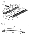
- Fig. 3
- eine Schrägansicht eines Sortierdecks mit zahlreichen erfindungsgemäßen Vorrichtungen zum Bremsen von Rollen,
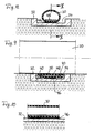
- Fig. 4
- einen vergrößerten Längsschnitt einer der in Fig.3 dargestellten erfindungsgemäßen Vorrichtungen im Zustand des Überrolltwerdens,
- Fig. 5
- eine Variante zu Fig.4, jedoch in unbelastetem Zustand,
- Fig. 6
- einen Querschnitt der in Fig.4 dargestellten erfindungsgemäßen Vorrichtung in unbelastetem Zustand,
- Fig. 7
- einen Querschnitt der in Fig.6 dargestellten Vorrichtung, jedoch in durch eine Rolle belastetem Zustand,
- Fig. 8
- einen Querschnitt einer gegenüber Fig.6 weitergebildeten erfindungsgemäßen Vorrichtung in unbelastetem Zu-Fig. 9 einen Querschnitt der in Fig.8 dargestellten Vorrichtung in durch eine Rolle belastetem Zustand,
- Fig.10
- den Längsschnitt X-X in Fig.8,
- Fig.11
- einen Querschnitt einer anderen gegenüber Fig.6 weitergebildeten Ausführungsform einer erfindungsgemäßen Vorrichtung in unbelastetem Zustand,
- Fig.12
- einen Querschnitt der in Fig.11 dargestellten Vorrichtung in durch eine Rolle belastetem Zustand,
- Fig.13
- eine schaltungstechnische Weiterbildung der in Fig.4 dargestellten erfindungsgemäßen Vorrichtung im Zustand des Überrolltwerdens,
- Fig.14
- die schaltungstechnisch wie in Fig.13 ausgestattete Vorrichtung nach dem Überrolltwerden,
- Fig.15
- eine schaltungstechnische Weiterbildung der in Fig.13 und 14 dargestellten Vorrichtung, im Zustand des Überrolltwerdens, und
- Fig.16
- eine weitere Variante zu Fig. 13, ebenfalls im Zustand des Überrolltwerdens.
- Fig. 1
- 2 shows an oblique view of a double carrier roller slitter known per se,
- Fig. 2
- 2 shows an oblique view of a single carrier roller slitter known per se,
- Fig. 3
- 2 shows an oblique view of a sorting deck with numerous devices according to the invention for braking rollers,
- Fig. 4
- 3 shows an enlarged longitudinal section of one of the devices according to the invention shown in FIG. 3 in the state of being rolled over,
- Fig. 5
- a variant of Figure 4, but in an unloaded state,
- Fig. 6
- 3 shows a cross section of the device according to the invention shown in FIG. 4 in the unloaded state,
- Fig. 7
- 6 shows a cross section of the device shown in FIG. 6, but in the state loaded by a roller,
- Fig. 8
- a cross section of an inventive device compared to Figure 6 in unloaded Zu-Fig. 9 shows a cross section of the device shown in FIG. 8 in the state loaded by a roller,
- Figure 10
- the longitudinal section XX in Figure 8,
- Figure 11
- 6 shows a cross section of another embodiment of a device according to the invention, which is further developed compared to FIG. 6, in the unloaded state,
- Figure 12
- 11 shows a cross section of the device shown in FIG. 11 in the state loaded by a roller,
- Figure 13
- 4 shows a circuit-related development of the device according to the invention shown in FIG. 4 in the state of being rolled over,
- Figure 14
- the device with circuitry as in Fig. 13 after being rolled over,
- Figure 15
- a circuit development of the device shown in Fig.13 and 14, in the state of being rolled over, and
- Figure 16
- a further variant of Fig. 13, also in the state of being rolled over.
In Fig.1 ist ein Rollenschneider 10 von bekannter Bauart mit
zwei Tragwalzen 12 dargestellt, die parallel zueinander in
einer gemeinsamen waagerechten Ebene angeordnete Drehachsen
haben, und denen Längsmesser 14 zum Zerteilen einer breiten
Papierbahn 16 vorgeschaltet sind. Die Längsmesser 14 sind wie
üblich als Schneidrollen ausgebildet, parallel zu den Achsen
der Tragwalzen 12 verstellbar sowie wegnehmbar und durch zusätzliche
gleichartige Längsmesser ergänzbar, so daß sie die
breite Papierbahn 16 in eine mehr oder weniger große Anzahl
einzelner Papierbahnen 18 zu zerschneiden vermögen. Die einzelnen
Papierbahnen 18 werden auf den Tragwalzen 12 zu je einer
Rolle 20 aufgewickelt und anschließend, beispielsweise
durch Absenken der Tragwalzen 12, an eine Rollbahn 22 abgegeben,
die durch einen Pfeil symbolisiert ist und 1 bis 2% Gefälle
in Richtung vom Rollenschneider 10 weg aufweist.In Fig.1 is a
In Fig.2 ist ein Rollenschneider 10 von ebenfalls bekannter
Bauart dargestellt, der nur eine einzige Tragwalze 12 aufweist
und wiederum mit Längsmessern 14 zum Zerteilen einer
breiten Papierbahn 16 in einzelne Papierbahnen 18 ausgestattet
ist. Auch hier werden die einzelnen Papierbahnen 18 zu je
einer Rolle 20 aufgewickelt, wobei jedoch jeder Rolle ein
Paar nicht dargestellter, an ihr stirnseitig angreifender Lagerzapfen
derart zugeordnet ist, daß die Rollen 20 abwechselnd
nach einer und der anderen Seite der Tragwalze 12 gegeneinander
versetzt angeordnet sind. Hier schließt sich beiderseits
des Rollenschneiders 10 je eine Rollbahn 22 an, die
wiederum ein Gefälle von 1 bis 2% in Richtung vom Rollenschneider
weg aufweist.In Figure 2, a
In Fig.3 wird vorausgesetzt, der in Fig.1 dargestellte Rollenschneider
10 habe die breite Papierbahn 16 in acht einzelne
Papierbahnen 18 zerschnitten und diese zu je einer Rolle
20 aufgewickelt. Der so entstandene Wurf von insgesamt acht
Rollen ist zu einer ersten Rampe 24 der Rollbahn 22 gelangt
und dort zum Stillstand gebracht worden. In Fig.3 sind noch
drei Rollen 20 eines vorangegangenen Wurfs sichtbar; diese
drei Rollen 20 sind auf dem Weg von der ersten Rampe 24 zu
einer zweiten Rampe 26, die ebenfalls zur Rollbahn 22 gehört
und den Zweck hat, die Rollen 20 auf einem Förderer 28 zum
Stillstand zu bringen, der sie anschließend quer zu ihrer
bisherigen Bewegungsrichtung weiterfördert.In Figure 3 it is assumed that the slitter shown in Figure 1
10 have the
Jede der in Fig.3 dargestellten Rampen 24 und 26 hat ein Gefälle,
des demjenigen der Rollbahn 22 entgegengerichtet und
dem Betrag nach größer ist. Zumindest die Rampe 24 ist jedoch
derart verstellbar, daß ihr Gefälle mit demjenigen der Rollbahn
22 in Größe und Richtung übereinstimmt. Jede der Rampen
24 und 26 ist mit einer Vielzahl Vorrichtungen zum Bremsen
der Rollen 20 ausgestattet, die in gleichen Abständen nebeneinander
derart angeordnet sind, daß auf jede der Rollen 20,
je nach deren Länge, zwei oder mehr solche Vorrichtungen
bremsend einwirken können.Each of the
In Fig.4 ist das Gestaltungs- und Wirkungsprinzip einer solchen
Vorrichtung zum Bremsen von Rollen skizziert. Die Vorrichtung
weist ein Kissen 30 auf, das von einem Abschnitt eines
Schlauches, beispielsweise Feuerwehrschlauches, mit einer
Länge von ungefähr 400 bis 600 mm oder alternativ von zwei an
ihren Rändern zusammengeschweißten oder -vulkanisierten biegsamen
Platten aus Kunststoff oder Gummi gebildet sein kann.
Das Kissen 30 ist mindestens an seinen Rändern in einem wannenartigen
Einsatz 32 befestigt, der seinerseits in die Rollbahn
22 eingebettet ist, beispielsweise gemäß Fig.3 in eine
der zur Rollbahn 22 gehörigen Rampen 24 oder 26. Der Einsatz
32 weist, im Längsschnitt gemäß Fig.4, aber auch im Querschnitt
beispielsweise gemäß Fig.6 und 7 betrachtet, eine U-förmige
Vertiefung 34 auf, in die das Kissen 30 derart eingebettet
ist, das es selbst von den schwersten vorkommenden
Rollen 20, die über das Kissen hinwegrollen, nicht gequetscht
oder sonstwie beschädigt werden kann.In Figure 4 is the design and operating principle of such
Device for braking rollers outlined. The device
has a
Das Kissen 30 ist mit einem Fluid, vorzugsweise Luft, unter
solchem Druck gefüllt, daß es von einer Rolle 20, die gemäß
Fig.4 in Richtung des Pfeils A über das Kissen hinwegrollt,
in zwei hermetisch voneinander getrennte Kammern unterteilt
wird, nämlich eine erste Kammer 36, die schon überrollt worden
ist, und eine zweite Kammer 38, die erst noch überrollt
werden wird. Die beiden Kammern 36 und 38 sind miteinander
durch einen Überströmkanal 40 verbunden, der eine von Hand
einstellbare oder automatisch regelbare Drosselstelle 42 enthält.
Zum Anschließen des Überströmkanals 40 ist das Kissen
30 in seinem bezüglich der Bewegungsrichtung A der Rolle 20
vorderen und hinteren Endbereich mit je einem Nippel 44 versehen.The
Es sei angenommen, die Rolle 20 in Fig.4 sei eine der drei in
Fig.3 einzeln dargestellten Rollen, die in Fig.3 im Begriff
sind, sich dem Förderer 28 zu nähern. Die in Fig.4 abgebildete
Rolle 20 ist über den Förderer 28 hinweg auf die zweite
Rampe 26 hinaufgerollt, die ein Gefälle entgegen der bisherigen
Bewegungsrichtung dieser Rolle aufweist. Beim Hinaufrollen
auf die zweite Rampe 26, und somit auf das in Fig.4 abgebildete
Kissen 30, verdrängt die Rolle 20 Luft aus der vor
ihr liegenden zweiten Kammer 38, und diese Luft strömt durch
den Überströmkanal 40 und dessen Drosselstelle 42 in die erste
Kammer 36. Dabei wird Bewegungsenergie der Rolle 20 zunächst
in Strömungsenergie, und diese in Wärme verwandelt;
die Bewegung der Rolle 20 wird also je nach Einstellung der
Drosselstelle 42 mehr oder weniger stark gebremst. Diese
Bremsung kann beispielsweise so eingestellt werden, daß die
Rolle 20 zum Stillstand kommt, ehe sie das Kissen 30 in Richtung
von links nach rechts in Fig.4 vollständig überrollt
hat. Die Drosselung wird vorzugsweise so eingestellt, daß das
Gefälle der zweiten Rampe 26 gerade eben ausreicht, die Rolle
20, sobald ihre ursprüngliche Bewegung zum Stillstand gekommen
ist, langsam auf den Förderer 28 zurückrollen zu lassen.Assume
Gemäß Fig.5 kann der in Fig.4 dargestellte wannenartige Einsatz
32 durch eine plattenförmige Unterlage 46 ersetzt sein,
die vorne und hinten leicht nach unten abgekantet ist; die
Nippel 44 sind im Bereich der Abkantungen angeordnet. Kissen
30 der in Fig.5 dargestellten Art können beispielsweise als
freitragende Brücken zwischen Widerlagern einer Tragkonstruktion
angeordnet sein.According to Figure 5, the trough-like insert shown in Figure 4
32 be replaced by a plate-shaped
In Fig.6 und 7 ist dargestellt, wie das hier schlauchförmige
Kissen 30 zweckmäßigerweise in bezug auf den Einsatz 32 mit
U-förmiger Vertiefung 34 bemessen ist. Das Kissen 30 hat gemäß
Fig.6 einen in unbelastetem Zustand kreisförmigen Querschnitt,
der gemäß Fig.7 von der über das Kissen hinwegrollenden
Rolle 20 vollständig flachgedrückt, jedoch durch die
Ränder des Einsatzes 32 davor geschützt ist, gequetscht zu
werden. In Fig.6 und 7 wird vorausgesetzt, daß das Kissen 30
im Bereich seines vorderen und seines hinteren Endes am Einsatz
32 befestigt ist, etwa so wie dies in Fig.4 dargestellt
ist. 6 and 7 show how this is
Fig.8 bis 10 zeigen eine andere Befestigungsart eines wiederum
schlauchförmigen Kissens 30, das hier jedoch in seinem unteren
Bereich zwischen einer zweischichtigen Unterlage 46 in
der Art eines Klettverschlusses und einer plattenförmigen
Einlage 48 angeordnet ist. Die obere Schicht der Unterlage 46
und die Einlage 48 können beide an das Kissen 30 angeklebt
oder anvulkanisiert oder durch dessen unteren Bereich hindurch
miteinander vernietet oder verschraubt sein. Die untere
Schicht der Unterlage 46 ist hingegen am Boden der Vertiefung
34 des Einsatzes 32 befestigt, beispielsweise festgeklebt.
Wesentlich ist, daß die Einlage 48 im gemäß Fig.9 von einer
Rolle 20 zusammengedrückten Zustand des Kissens 30 interne
Überströmkanäle 40 freiläßt, in denen eine gedrosselte Fluidströmung
zwischen den beiden Kammern 36 und 38 möglich ist.Fig. 8 to 10 show another type of attachment in turn
Wie aus Fig.9 ersichtlich ist, sind die beiden Längsränder
des Kissens 30 weniger stark als in Fig.7 flachgedrückt; dies
trägt dazu bei, daß das Kissen 30 bei der in Fig.8 bis 10
dargestellten Anordnung eine besonders lange Betriebslebensdauer
aufweist, d.h. besonders zahlreichen Überrollzyklen
stand hält.As can be seen from Fig. 9, the two longitudinal edges
of the
Eine ähnliche Wirkung läßt sich gemäß Fig.11 und 12 auch ohne
plattenförmige Einlage erzielen, sofern eine an ihren Längsrändern
abgeflachte, z.B.abgeschrägte Unterlage 46 vorgesehen
ist. Beiden in Fig.8 bis 10 einerseits sowie in Fig.11 und 12
andererseits dargestellten Ausführungsformen ist ferner gemeinsam,
daß sie ohne äußeren Überströmkanal auskommen. Allerdings
muß die Unterlage 46 und/oder die Einlage 48 so bemessen
sein, daß die bei flachgedrücktem Kissen 30 verbleibenden
internen Überströmkanäle 40 eine dem jeweiligen Verwendungszweck
angepaßte Drosselwirkung haben.A similar effect can also be achieved according to FIGS. 11 and 12
Achieve plate-like inlay, if one on its longitudinal edges
flattened, e.g. beveled
Eine Möglichkeit, die Drosselwirkung von der Bewegungsrichtung
der Rolle 20 abhängig zu machen, ist in Fig.13 und 14
dargestellt. Dort ist wiederum ein externer Überströmkanal 40
vorgesehen, der jedoch im Gegensatz zu Fig.4 zwei Drosselstellen
42 und 42' aufweist, die hintereinander sowie parallel
zu je einem Rückschlagventil 50 bzw. 50' angeordnet sind.
Das Rückschlagventil 50 widersetzt sich einer Strömung von
rechts nach links, zwingt also bei einer Bewegung der Rolle
20 von links nach rechts das aus der zweiten Kammer 38 verdrängte
Fluid, durch die Drosselstelle 42 zu strömen. Das
Rückschlagventil 50' widersetzt sich hingegen einer Fluidströmung
von links nach rechts und zwingt somit das bei einer
Bewegung der Rolle 20 von rechts nach links aus der ersten
Kammer 36 verdrängte Fluid, durch die Drosselstelle 42' zu
strömen.One way of throttling the direction of movement
to make the
Bei der bevorzugten Verwendung von Luft als Fluid ist das
Kissen 30 ständig an eine Druckluftquelle 52 angeschlossen,
und zwar gemäß Fig.13 und 14 über den Überströmkanal 40, ein
Absperrventil 54 und ein Druckminderventil 56.In the preferred use of air as a fluid, this is
Gemäß Fig.15 ist an das Kissen 30 zusätzlich ein gesondertes
Entlastungsventil 58 angeschlossen, und zwischen dem Absperrventil
54 und dem Überströmkanal 40 ist ein Rückschlagventil
60 angeordnet. Je eine solche Schaltung kann beispielsweise
den Kissen 30 an der ersten Rampe 24 zugeordnet sein, um die
Möglichkeit zu schaffen, einzelne Rollen 20 eines Wurfs selektiv
weiter rollen zu lassen, nachdem zunächst der Wurf
insgesamt von der entgegen der Abrollrichtung geneigten ersten
Rampe 24 angehalten und diese Rampe dann soweit abgesenkt
worden ist, daß sich nur diejenigen Rollen 20 weiterbewegen
können, in deren Bewegungsbahn im wesentlichen widerstandslos
zusammendrückbare Kissen 30 liegen. Diejenigen Kissen 30, die
im aufgeblähten Zustand gegen eine stirnseitige Kante einer
Rolle 20 drücken würden und diese, wenn es sich z.B. um eine
Papierrolle handelt, beschädigen könnten, lassen sich durch
Öffnen des ihnen gemäß Fig.15 zugeordneten Entlastungsventils
58 oder, in der Schaltung gemäß Fig.13 und 14, durch die in
Fig. 14 abgebildete Stellung des Absperrventils 54 ständig
unwirksam machen. According to FIG. 15, there is also a
In Fig.16 wird vorausgesetzt, das dort dargestellte Kissen 30
werde immer in Richtung von rechts nach links, in Richtung
des Pfeils A', überrollt und habe - zusammen mit weiteren, in
einer Reihe mit ihm angeordneten Kissen 30 - die Aufgabe, jeweils
eine von rechts kommende Rolle 20 derart abzubremsen,
daß sie auf dem Förderer 28 zum Stillstand kommt, diesen also
nicht erst überrollt.16 it is assumed that the
Das Kissen 30 in Fig.16 ist als solches ebenso gestaltet, wie
das in Fig.4 dargestellte Kissen 30; in Fig.16 ist jedoch
aus dem genannten Grund die rechte Kammer des Kissens als
erste Kammer 36, und die linke als zweite Kammer 38, bezeichnet.
Ein wesentlicher Unterschied gegenüber den bisher beschriebenen
Ausführungsbeispielen besteht darin, daß gemäß
Fig.16 kein Überströmkanal 40 vorgesehen ist, weder ein externer
noch ein interner. Die zweite Kammer 38 ist an eine
Drosselstelle 42 in Gestalt eines einstellbaren Drosselventils
angeschlossen, über das von der Rolle 20 aus der zweiten
Kammer 38 verdrängte Luft ins Freie abgelassen wird. Die erste
Kammer 36 ist über eine Drosselstelle 42', ein Absperrventil
54 und ein Druckminderventil 56 an eine Druckluftquelle
52 angeschlossen, von der aus das Kissen 30 jeweils nachgefüllt
wird. Zwischen der Drosselstelle 42' und dem Absperrventil
54 ist ein Rückschlagventil 60 angeordnet, das ein
Ausströmen von Luft aus der ersten Kammer 36 verhindert.As such, the
Claims (12)
dadurch gekennzeichnet, daß
characterized in that
dadurch gekennzeichnet, daß die Drosselstelle (42) einstellbar ist.Device according to claim 1,
characterized in that the throttle point (42) is adjustable.
dadurch gekennzeichnet, daß der die Drosselstelle (42) enthaltende Kanal ein Überströmkanal (40) ist, der die beiden Kammern (36, 38) miteinander verbindet.Device according to claim 1 or 2,
characterized in that the channel containing the throttle point (42) is an overflow channel (40) which connects the two chambers (36, 38) to one another.
dadurch gekennzeichnet, daß der Überströmkanal (40) zwei unabhängig voneinander einstellbare, hintereinander angeordnete Drosselstellen (42, 42') enthält, denen je eines von zwei in entgegengesetzten Strömungsrichtungen öffnenden Rückschlagventilen (50, 50') parallelgeschaltet ist.Device according to claim 3,
characterized in that the overflow channel (40) contains two throttle points (42, 42 ') which can be set independently of one another and which are arranged one behind the other and each of which is connected in parallel with one of two check valves (50, 50') opening in opposite flow directions.
dadurch gekennzeichnet, daß das Kissen (30) in mindestens einem streifenförmigen, bezogen auf die Bewegungsrichtung der Rollen (20) längsgerichteten Bereich (60) nicht ausreichend abgestützt ist, um vom Gewicht einer Rolle (20) in einer die Kammern (36, 38) vollständig voneinander trennenden Weise flachgedrückt zu werden, sodaß in diesem Bereich (60) der die beiden Kammern (36, 38) verbindende Überströmkanal (40) im Kissen (20) selbst ausgebildet ist.Device according to claim 3,
characterized in that the cushion (30) is not adequately supported in at least one strip-shaped region (60) which is longitudinal in relation to the direction of movement of the rollers (20) in order to be able to support the weight of a roller (20) in one of the chambers (36, 38) to be flattened in a completely separating manner so that the overflow channel (40) connecting the two chambers (36, 38) is formed in the cushion (20) itself in this area (60).
dadurch gekennzeichnet, daß das Kissen (20) auf einer Unterlage (46) befestigt ist, die zwei voneinander abgewandte längsge- richtete Bereiche (60) des Kissens (30) unabgestützt läßt.Device according to claim 5,
characterized in that the cushion (20) is fastened to a base (46) which leaves two longitudinal areas (60) of the cushion (30) facing away from one another unsupported.
dadurch gekennzeichnet, daß das Kissen (30) in einer U-förmigen Vertiefung (34) der Rollbahn (22) gegen Zerquetschtwerden geschützt angeordnet ist.Device according to one of claims 1 to 6,
characterized in that the cushion (30) is arranged in a U-shaped recess (34) of the runway (22) so as to be protected against being crushed.
dadurch gekennzeichnet, daß die Vertiefung (34) in einem starren Einsatz (32) ausgebildet ist, der seinerseits in die Rollbahn (22) eingebettet ist.Device according to claim 7,
characterized in that the recess (34) is formed in a rigid insert (32) which in turn is embedded in the runway (22).
dadurch gekennzeichnet, daß das Kissen (30) eine steife Einlage (48) enthältDevice according to one of claims 1 to 8,
characterized in that the pillow (30) contains a rigid insert (48)
dadurch gekennzeichnet, daß das Kissen (30) durch eine Unterlage (46) in der Art eines Klettverschlusses am Verrutschen gehindert ist.Device according to one of claims 1 to 9,
characterized in that the cushion (30) is prevented from slipping by a pad (46) in the manner of a Velcro fastener.
dadurch gekennzeichnet, daß das Kissen (30) über ein Absperrventil (54) an eine Druckluftquelle (52) angeschlossen ist.Device according to one of claims 1 to 10,
characterized in that the cushion (30) is connected to a compressed air source (52) via a shut-off valve (54).
dadurch gekennzeichnet, daß zwischen der Druckluftquelle (52) und dem Absperrventil (54) ein einstellbares Druckminderventil (56) angeordnet ist.Device according to claim 11,
characterized in that an adjustable pressure reducing valve (56) is arranged between the compressed air source (52) and the shut-off valve (54).
Applications Claiming Priority (2)
| Application Number | Priority Date | Filing Date | Title |
|---|---|---|---|
| DE2000164058 DE10064058A1 (en) | 2000-12-21 | 2000-12-21 | Device for braking rolls, in particular paper rolls |
| DE10064058 | 2000-12-21 |
Publications (2)
| Publication Number | Publication Date |
|---|---|
| EP1216945A2 true EP1216945A2 (en) | 2002-06-26 |
| EP1216945A3 EP1216945A3 (en) | 2004-05-26 |
Family
ID=7668305
Family Applications (1)
| Application Number | Title | Priority Date | Filing Date |
|---|---|---|---|
| EP01129226A Withdrawn EP1216945A3 (en) | 2000-12-21 | 2001-12-10 | Device for braking rolls, especially paper rolls |
Country Status (2)
| Country | Link |
|---|---|
| EP (1) | EP1216945A3 (en) |
| DE (1) | DE10064058A1 (en) |
Cited By (1)
| Publication number | Priority date | Publication date | Assignee | Title |
|---|---|---|---|---|
| WO2014174151A1 (en) * | 2013-04-24 | 2014-10-30 | Sovellusmestarit Oy | Method and apparatus for receiving of a cylindrical body and the use of the method and the apparatus |
Citations (4)
| Publication number | Priority date | Publication date | Assignee | Title |
|---|---|---|---|---|
| US2562035A (en) * | 1948-07-14 | 1951-07-24 | United States Steel Corp | Devices for positioning and handling cylindrical articles |
| US5402980A (en) * | 1992-07-28 | 1995-04-04 | Champion International Corporation | Wound paper roll support apparatus |
| EP0705783A1 (en) * | 1994-09-21 | 1996-04-10 | Valmet Corporation | Method and assembly for stopping a set of rolls |
| US6089495A (en) * | 1997-12-05 | 2000-07-18 | Voith Sulzer Papiertechnik Patent Gmbh | Winding device and method for a reel cutter |
Family Cites Families (3)
| Publication number | Priority date | Publication date | Assignee | Title |
|---|---|---|---|---|
| US4541578A (en) * | 1982-08-11 | 1985-09-17 | Murata Kikai Kabushiki Kaisha | Doffing apparatus in automatic winder |
| DE3609086A1 (en) * | 1986-03-18 | 1987-10-01 | Wifag Maschf | DEVICE FOR BE- OR. UNLOADING A ROLLING STAND OF A ROLLING ROTATION PRINTING MACHINE WITH OR OF PAPER ROLLS |
| GB2209328B (en) * | 1987-09-03 | 1991-09-25 | Isowa Industry Co | Cardboard web feeding device for corrugator. |
-
2000
- 2000-12-21 DE DE2000164058 patent/DE10064058A1/en not_active Withdrawn
-
2001
- 2001-12-10 EP EP01129226A patent/EP1216945A3/en not_active Withdrawn
Patent Citations (4)
| Publication number | Priority date | Publication date | Assignee | Title |
|---|---|---|---|---|
| US2562035A (en) * | 1948-07-14 | 1951-07-24 | United States Steel Corp | Devices for positioning and handling cylindrical articles |
| US5402980A (en) * | 1992-07-28 | 1995-04-04 | Champion International Corporation | Wound paper roll support apparatus |
| EP0705783A1 (en) * | 1994-09-21 | 1996-04-10 | Valmet Corporation | Method and assembly for stopping a set of rolls |
| US6089495A (en) * | 1997-12-05 | 2000-07-18 | Voith Sulzer Papiertechnik Patent Gmbh | Winding device and method for a reel cutter |
Cited By (4)
| Publication number | Priority date | Publication date | Assignee | Title |
|---|---|---|---|---|
| WO2014174151A1 (en) * | 2013-04-24 | 2014-10-30 | Sovellusmestarit Oy | Method and apparatus for receiving of a cylindrical body and the use of the method and the apparatus |
| CN105324321A (en) * | 2013-04-24 | 2016-02-10 | 索维斯姆斯塔瑞塔有限公司 | Method and apparatus for receiving of a cylindrical body and the use of the method and the apparatus |
| US9784331B2 (en) | 2013-04-24 | 2017-10-10 | Sovellusmestarit Oy | Method and apparatus for receiving of a cylindrical body and the use of the method and the apparatus |
| EP2989034B1 (en) * | 2013-04-24 | 2020-10-14 | Sovellusmestarit Oy | Method for receiving paper reels in papermaking industry |
Also Published As
| Publication number | Publication date |
|---|---|
| EP1216945A3 (en) | 2004-05-26 |
| DE10064058A1 (en) | 2002-07-04 |
Similar Documents
| Publication | Publication Date | Title |
|---|---|---|
| DE3406719C2 (en) | ||
| AT401922B (en) | WINDING MACHINE FOR SHAPED GOODS, IN PARTICULAR PAPER | |
| DE1017017B (en) | Device for winding up a material, in particular paper, web | |
| DE2320158C3 (en) | Conveyor device for objects with a convex surface, e.g. rollers | |
| DE60009844T2 (en) | Conveying direction switching device in a roller conveyor | |
| DE3706834C2 (en) | ||
| EP0161569B1 (en) | Device for winding or unwinding continually fed preferably overlapping printed articles | |
| DE10020909A1 (en) | Device for conveying a supply roll | |
| DE4321314C2 (en) | Device for loading and / or unloading containers | |
| DE1114377B (en) | Machine for winding a web of material, in particular a paper web, onto rolls | |
| EP1108669A2 (en) | Reel winding device, in particular for a reel slitting machine | |
| EP1216945A2 (en) | Device for braking rolls, especially paper rolls | |
| EP0905070B1 (en) | Winding machine with king rolls | |
| EP1373111B1 (en) | Winding machine for rolling up a strip of material, especially a paper or cardboard strip, into rolls | |
| DE3222177C2 (en) | ||
| DE2014436C3 (en) | Device for stopping conveyor boxes in a belt conveyor system | |
| DE3237598C2 (en) | Driven roller conveyor with pressure-free accumulation section | |
| EP0623438B1 (en) | Feeding device for calender | |
| DE3812863A1 (en) | ROLL CONVEYOR | |
| DE4441278A1 (en) | Cutting device for cutting tea=bags from paper web material | |
| DE19633670A1 (en) | Mechanism permitting easy interchange of rollers in calender stack | |
| DE3117464A1 (en) | Device for removing roller rods from a rod position | |
| EP0987204B1 (en) | Roll winding device | |
| EP0337145A2 (en) | Device for hydrostatically supporting rolls of a rolling mill | |
| DE202005008319U1 (en) | Conveying device for pallets and the like. |
Legal Events
| Date | Code | Title | Description |
|---|---|---|---|
| PUAI | Public reference made under article 153(3) epc to a published international application that has entered the european phase |
Free format text: ORIGINAL CODE: 0009012 |
|
| AK | Designated contracting states |
Kind code of ref document: A2 Designated state(s): AT BE CH CY DE DK ES FI FR GB GR IE IT LI LU MC NL PT SE TR |
|
| AX | Request for extension of the european patent |
Free format text: AL;LT;LV;MK;RO;SI |
|
| PUAL | Search report despatched |
Free format text: ORIGINAL CODE: 0009013 |
|
| AK | Designated contracting states |
Kind code of ref document: A3 Designated state(s): AT BE CH CY DE DK ES FI FR GB GR IE IT LI LU MC NL PT SE TR |
|
| AX | Request for extension of the european patent |
Extension state: AL LT LV MK RO SI |
|
| STAA | Information on the status of an ep patent application or granted ep patent |
Free format text: STATUS: THE APPLICATION IS DEEMED TO BE WITHDRAWN |
|
| 18D | Application deemed to be withdrawn |
Effective date: 20040701 |