EP1216906A2 - Vacuum booster - Google Patents
Vacuum booster Download PDFInfo
- Publication number
- EP1216906A2 EP1216906A2 EP01130238A EP01130238A EP1216906A2 EP 1216906 A2 EP1216906 A2 EP 1216906A2 EP 01130238 A EP01130238 A EP 01130238A EP 01130238 A EP01130238 A EP 01130238A EP 1216906 A2 EP1216906 A2 EP 1216906A2
- Authority
- EP
- European Patent Office
- Prior art keywords
- valve
- vacuum
- cylinder
- valve seat
- chamber
- Prior art date
- Legal status (The legal status is an assumption and is not a legal conclusion. Google has not performed a legal analysis and makes no representation as to the accuracy of the status listed.)
- Granted
Links
Images



Classifications
-
- B—PERFORMING OPERATIONS; TRANSPORTING
- B60—VEHICLES IN GENERAL
- B60T—VEHICLE BRAKE CONTROL SYSTEMS OR PARTS THEREOF; BRAKE CONTROL SYSTEMS OR PARTS THEREOF, IN GENERAL; ARRANGEMENT OF BRAKING ELEMENTS ON VEHICLES IN GENERAL; PORTABLE DEVICES FOR PREVENTING UNWANTED MOVEMENT OF VEHICLES; VEHICLE MODIFICATIONS TO FACILITATE COOLING OF BRAKES
- B60T13/00—Transmitting braking action from initiating means to ultimate brake actuator with power assistance or drive; Brake systems incorporating such transmitting means, e.g. air-pressure brake systems
- B60T13/10—Transmitting braking action from initiating means to ultimate brake actuator with power assistance or drive; Brake systems incorporating such transmitting means, e.g. air-pressure brake systems with fluid assistance, drive, or release
- B60T13/24—Transmitting braking action from initiating means to ultimate brake actuator with power assistance or drive; Brake systems incorporating such transmitting means, e.g. air-pressure brake systems with fluid assistance, drive, or release the fluid being gaseous
- B60T13/46—Vacuum systems
- B60T13/52—Vacuum systems indirect, i.e. vacuum booster units
- B60T13/57—Vacuum systems indirect, i.e. vacuum booster units characterised by constructional features of control valves
Definitions
- First and second ports 28 and 29 are formed in the valve cylinder 10.
- One end of the first port 28 opens into the vacuum chamber 2, and the other end thereof opens into the front annular chamber 45A.
- One end of the second port 29 opens into the operating chamber 3, and the other end thereof opens between the vacuum introduction valve seat 30 and the atmosphere introduction valve seat 31.
- the second port 29 communicates with the rear annular chamber 45B via a communication hole 47, which is formed at the base of the ring-shaped projection 10a and is parallel to the axial line of the valve cylinder 10.
- the communication hole 47 which is parallel to the axial line of the valve cylinder 10, can be easily formed by using a core cylindrical pin during the process employed for forming the valve cylinder 10.
Landscapes
- Engineering & Computer Science (AREA)
- Transportation (AREA)
- Mechanical Engineering (AREA)
- Braking Systems And Boosters (AREA)
Abstract
Description
- The present invention relates to a vacuum booster used for the servo operation of a brake master cylinder for a vehicle. In particular, the present invention pertains to an improved vacuum booster, wherein a booster piston is located in a booster shell to divide the interior of the booster shell into a front vacuum chamber communicating with a vacuum source and a rear operating chamber, wherein a valve piston fitted into a valve cylinder so as to be slidable forward and backward, an input rod that connects the front end thereof to the valve piston, a control valve that, in accordance with the forward and backward movement of the input rod between the valve piston and the valve cylinder, alters the communication of the operating chamber with either the vacuum chamber or the atmosphere, and an input return spring that impels the input rod backward are arranged in the valve cylinder that communicates with the booster piston, wherein the control valve is constituted by a ring-shaped vacuum introduction valve seat formed in the valve cylinder, an atmosphere introduction valve seat formed in the valve piston and positioned inside the vacuum introduction valve seat, a valve element that includes: a ring-shaped attachment bead portion securely supported at the inner wall of the valve cylinder; an elastic cylinder axially extending from the attachment bead portion; and a valve portion connected, flange-like, to the front end of the elastic cylinder and located facing the vacuum introduction valve seat and the atmosphere introduction valve seat, on which the valve portion is to be seated, and wherein a first port that communicates with the vacuum chamber is opened to the outer wall side of the vacuum introduction valve seat, and a second port that communicates with the operating chamber is opened between the vacuum introduction valve seat and the atmosphere introduction valve seat, thus enabling the inside of the valve portion to communicate with the atmosphere.
- Vacuumboosters are well known, as is disclosed, for example, in JP-B-58-48923U.
- The periphery of the control valve of the vacuum booster disclosed in the referenced publication is shown in Fig. 6. As is apparent from Fig. 6, a
control valve 38 of a conventional vacuum booster includes: a ring-shaped vacuumintroduction valve seat 30, which is formed in avalve cylinder 10; an atmosphereintroduction valve seat 31, which is formed on avalve piston 18 that is connected to aninput rod 20 and is located inside the vacuumintroduction valve seat 30; avalve element 34, which includes a ring-shapedattachment bead portion 34b that is securely supported by the inner wall of thevalve cylinder 10, anelastic cylinder 34c that extends forward from theattachment bead portion 34b, and a ring-shaped valve disk 34a that is connected, flange-like, to the front end of thecylinder 34c and is positioned opposite the vacuumintroduction valve seat 30 and the atmosphereintroduction valve seat 31 on which it is seated; and avalve spring 36, which impels thevalve disk 34a in the direction in which it is seated on the vacuumintroduction valve seat 30 and the atmosphereintroduction valve seat 31. Afirst port 28, which communicates with thevacuum chamber 2, opens to the outer wall side of thevacuum introduction valve 30, and asecond port 29, which communicates with theoperating chamber 3, is opened between the vacuumintroduction valve seat 30 and the atmosphereintroduction valve seat 31. Anatmosphere introduction port 39, which communicates with the inner wall of thevalve disk 34a, is formed at the rear of thevalve cylinder 10. In addition, aninput return spring 41, which impels theinput rod 20 to the rear, is retracted between thevalve cylinder 10 and theinput rod 20, while abooster piston 4 is integrally coupled with thevalve cylinder 10. - Generally, for this vacuum booster, since the initial operating force exerted by the
input rod 20 is determined in accordance with the set load of theinput return spring 41, it is preferable that the set load of theinput return spring 41 be as small as possible in order to reduce the required operating force. - Assume that the atmosphere
introduction valve seat 31 is released from thevalve portion 34a of thevalve element 34 by moving theinput rod 20 forward against the set load of theinput return spring 41, that thevalve portion 34a is seated on the vacuumintroduction valve seat 30, and that a forward propulsive force produced by a pressure difference between thevacuum chamber 2 and theoperating chamber 3 is exerted on thebooster piston 4. Since in this state, atmospheric pressure acts on the front face of thevalve portion 34a and a vacuum pressure, produced by thevacuum chamber 2, acts on the rear face, it is necessary for the set load of the valve spring to be satisfactorily large in order to prevent the propulsive force produced by the pressure difference from releasing thevalve portion 34a from the vacuumintroduction valve seat 30. However, when the set load of thevalve spring 36 is large, accordingly, the set load of theinput return spring 41 must also be large. Otherwise, when the operating force applied to theinput rod 20 is released, the set load of thevalve spring 36 will prevent thevalve portion 34a from separating from the vacuumintroduction valve seat 30. This factor prevents any reduction in the set load of theinput return spring 41 of the conventional vacuum booster. - To resolve this problem, it is one objective of the present invention to provide a vacuum booster wherein a smaller set load is provided for a valve spring, and accordingly, the set load of an input return spring can be reduced, as can the initial operating force applied to the
input rod 20. - To achieve the above objective, according to a first aspect of the invention, there is provided a vacuumbooster, comprising:
- a booster shell;
- a booster piston accommodated in the booster shell to divide the interior of the booster shell into a front vacuum chamber communicating with a vacuum source and a rear operating chamber;
- a valve cylinder connected to the booster piston;
- a valve piston fitted into the valve cylinder so as to be slidable forward and backward;
- an input rod connected to the valve piston at a front end thereof;
- an input return spring urging the input rod backward; and
- a control valve arranged within the valve cylinder, for
changing over the communication of the operating chamber with
one of the vacuum chamber and the atmosphere in accordance
with the forward and backward movement of the input rod, the
control valve including:
- a ring-shaped vacuum introduction valve seat formed in the valve cylinder;
- an atmosphere introduction valve seat formed in the valve piston and disposed inside the vacuum introduction valve seat;
- a valve element having: a ring-shaped attachment bead portion securely held with respect to an inner wall of the valve cylinder; an elastic cylinder axially extending from the attachment bead portion; and, an annular valve portion connected in a flange shape to a front end of the elastic cylinder and facing the vacuum introduction valve seat and the atmosphere introduction valve seat, on which the valve portion is to be seated; and
- a valve spring urging the valve portion in a direction that the valve portion is seated on the vacuum introduction valve seat and the atmosphere introduction valve seat, wherein a first port that communicates with the vacuum chamber is opened to an outer periphery side of the vacuum introduction valve seat, a second port that communicates with the operating chamber is opened between the vacuum introduction valve seat and the atmosphere introduction valve seat, and an inner periphery side of the valve portion is communicated with the atmosphere,
-
- According to the first aspect, when the input rod is moved forward against the set load of the input return spring, and when the atmosphere introduction valve seat is separated from the valve portion of the valve element while the valve disk is seated on the vacuum introduction valve seat, the vacuum pressure, which is transmitted from the first port to the front annular chamber of the valve cylinder, acts on the front face of the valve portion facing the front annular chamber, while the atmospheric pressure, which is transmitted from the second port to the rear annular chamber, acts on the rear face of the valve seat facing the rear annular chamber. Thus, not only in accordance with the set load of the valve spring, but also in accordance with the pressure difference between the front and rear annular chambers, the valve portion is urged in the direction in which it will be seated on the vacuum introduction valve seat. Therefore, the set load of the valve spring can be reduced by a value equivalent to the urging force produced by the pressure difference. And accordingly, only a small set load is required for the input return spring that impels the input rod to the rear, so that the load imposed by the initial operation of the input rod can be reduced.
- According to a second aspect, in addition to the first aspect, the valve portion includes a sealing lip in the outer periphery thereof, bent rearwardly so as to be slidably contacted with the inner wall of the valve cylinder.
- According to the second aspect, when the atmosphere introduction valve seat is separated from the valve portion of the valve element, and when the valve portion is seated on the vacuum introduction valve seat, the force with which the sealing lip is held closely against the inner wall of the valve cylinder is increased due to the pressure difference generated between the front and rear annular chambers, and between the front and rear annular chambers an airtight condition can be obtained.
- In addition to the first and second aspect, according to a third aspect, a through hole communicating with the rear annular chamber and the first port is formed in the valve cylinder parallel to an axial line of the valve cylinder.
- According to the third aspect, at the same time as the valve cylinder is formed, the through hole can also be formed by a core cylindrical pin. Thus, a valve cylinder having a communication path can be provided at a low cost.
-
- Fig. 1 is a vertical cross-sectional view of a single -type vacuum booster according to the invention wherein an input rod is halted;
- Fig. 2 is an enlarged diagram showing a portion II in Fig. 1;
- Fig. 3 is a diagram, corresponding to Fig. 2, used to explain the servo operating state;
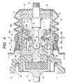
- Fig. 4 is a diagram, corresponding to Fig. 2, used to explain the servo release process;
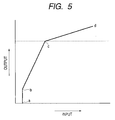
- Fig. 5 is a graph showing the servo characteristic of the vacuum booster; and
- Fig. 6 is a cross-sectional view of a control valve element in a conventional vacuum booster.
-
- One embodiment of the present invention will now be described while referring to Figs. 1 - 5.
- First, in Figs. 1 and 2, a booster shell 1 of a vacuum booster B is formed of a pair of a
front half shell 1a and arear half shell 1b, the facing ends of which are connected with each other. Thehalf shells rear half shell 1b is secured, via thetie rods 8, to the front wall F of the vehicle compartment, and a cylinder body Ma of a brake master cylinder M is secured to thefront half shell 1a. - The inside of the booster shell 1 is divided into a
front vacuum chamber 2 and arear operating chamber 3 by abooster piston 4 which is reciprocally accommodated in the booster shell 1, and adiaphragm 5 which is bonded over the rear face of thebooster piston 4 and sandwiched between thehalf shells vacuum chamber 2 is connected, via avacuum pipe 14, to a vacuum source V (e.g., the interior of the intake manifold of a combustion engine). - The
booster piston 4 and thediaphragm 5 are also penetrated by thetie rods 8, and thediaphragm 5, especially, is fitted over thetie rods 8 so that the airtight condition existing between thevacuum chamber 2 and theoperating chamber 3 can be maintained, while the movement of thebooster piston 4 is permitted. - The
booster piston 4, which is formed of stainless steel, is formed in a ring shape, and acylinder valve 10 made of a synthetic resin, is integrally coupled with the centers of thebooster piston 4 and thediaphragm 5. Thevalve cylinder 10 is slidably supported, via abearing member 13 having a sealing lip, to asupport cylinder 12 projecting rearwardly from the center of therear half shell 1b. - Arranged within the
valve cylinder 10 are avalve piston 18, aninput rod 20 which is connected to thevalve piston 18, and acontrol valve 38 which alters the communicaiton of theoperating chamber 3 with either thevacuum chamber 2 or the atmosphere in accordance with the movement of theinput rod 20. - The
valve piston 18 is slidably fitted into a guide hole 11 formed in thevalve cylinder 10, and areaction piston 17 is formed at the front portion thereof, via aneck portion 18b, while a flange-shaped atmosphereintroduction valve seat 31 is formed at the rear portion thereof. Further, in thecylinder valve 10, there is formed a ring-shaped vacuumintroduction valve seat 30 positioned concentrically with the atmosphericintroduction valve seat 31 to enclose the atmosphericintroduction valve seat 31. - A
connection hole 18a is formed in thevalve piston 18 that opens to the rear of the atmosphericintroduction valve seat 31, and aspherical front end 20a of theinput rod 20 is fitted into theconnection hole 18a. Part of thevalve piston 18 is calked to prevent it from slipping off thefront end 20a, and as a result, theinput rod 20 is pivotally coupled with thevalve piston 18. - In addition, one
common valve element 34 is attached to thevalve cylinder 10, for cooperating with the vacuumintroduction valve seat 30 and the atmosphereintroduction valve seat 31. Thevalve seat 34 is entirely formed of an elastic material, such as rubber, and includes a ring-shapedattachment bead portion 34b, anelastic cylinder 34c that extends forward from theattachment bead portion 34b, and a flange-shapedvalve portion 34a that projects radially outward from the front end of theelastic cylinder 34c. A ring-shaped reinforcingplate 44 is inserted from the inner wall of thevalve portion 34a by mold coupling. Further, a ring-shaped sealinglip 37, which is bent to the rear, is integrally formed with the outer wall of thevalve portion 34a. - The
attachment bead portion 34b is sandwiched between a pair ofvalve holders projection 10a. The ring-shapedprojection 10a is integrally formed in the inner wall of thevalve cylinder 10 together with the vacuumintroduction valve seat 30. At this time, therear valve holder 35B is fitted into the inner wall of thevalve cylinder 10 via an O-ring 43. And, thevalve portion 34a is located facing the atmosphereintroduction valve seat 31 and the vacuumintroduction valve seat 30, so that thevalve portion 34a can be seated on them. - A
valve spring 36 is shrinkingly disposed between the reinforcingplate 44 of thevalve portion 34a and theinput rod 20 and impels thevalve portion 34a in the direction that thevalve portion 34a seats on the valve seats 30 and 31. As a result, acontrol valve 38 is constituted by the vacuumintroduction valve seat 30, the atmosphereintroduction valve seat 31, thevalve element 34 and thevalve spring 36. - An
input return spring 41 is shrinkingly disposed between therear valve holder 35B and theinput rod 20, and with this arrangement, the front andrear valve holders shapedprojection 10a of thevalve cylinder 10, while theinput rod 20 is urged to the rear. - A front
annular chamber 45A that encloses the vacuumintroduction valve seat 30 is formed in the ring-shapedprojection 10a on the inner wall of thevalve cylinder 10, and the front face of thevalve portion 34a faces thering chamber 45A. The inner wall of the frontannular chamber 45A, which radially is near the exterior, extends to the rear from the vacuumintroduction valve seat 30, and the sealinglip 37 on the outer wall of thevalve portion 34a closely contacts with and slides along the inner wall of thering chamber 45A. Therefore, the frontannular chamber 45A is closed when thevalve portion 34a is seated on the vacuumintroduction valve seat 30. - Furthermore, a rear
annular chamber 45B to which the rear face of thevalve portion 34a is faced, is defined inside the ring-shapedprojection 10a by using thevalve portion 34a with the sealinglip 37. - First and
second ports valve cylinder 10. One end of thefirst port 28 opens into thevacuum chamber 2, and the other end thereof opens into the frontannular chamber 45A. One end of thesecond port 29 opens into the operatingchamber 3, and the other end thereof opens between the vacuumintroduction valve seat 30 and the atmosphereintroduction valve seat 31. Thesecond port 29 communicates with the rearannular chamber 45B via acommunication hole 47, which is formed at the base of the ring-shapedprojection 10a and is parallel to the axial line of thevalve cylinder 10. Thecommunication hole 47, which is parallel to the axial line of thevalve cylinder 10, can be easily formed by using a core cylindrical pin during the process employed for forming thevalve cylinder 10. - The both ends of a
boot 40, which covers thevalve cylinder 10 and can be stretched or contracted, are fitted around theinput rod 20 and to the rear end of asupport cylinder 12 of therearhalf shell 1b. Anatmosphere inlet port 39 communicating with the inside of thevalve element 34 is formed in the rear surface of theboot 40. Afilter 42, which filters the air that flows through theatmosphere inlet port 39, is located between the outer wall of theinput rod 20 and the inner wall of thevalve cylinder 10. Thefilter 42 has a flexibility so that the relative movements of theinput rod 20 and thevalve cylinder 10 are not interfered therewith. - A key 32 which determines the retraction limits for the
booster piston 4 and thevalve piston 18 is attached to thevalve cylinder 10 so that the key 32 can be moved by a predetermined distance in the axial direction. At the internal end of the key 32, afork 32b extends across theneck portion 18b located between thevalve piston 18 and thereaction piston 17. Anouter end 32a of the key 32 is located to face with the front face of astopper wall 19 provided in thesupport cylinder 12 of therear half shell 1b. Therefore, when the key 32 contacts thestopper wall 19, the limit of the retraction of thebooster piston 4 and thevalve cylinder 10 is determined, and when the rear end of thereaction piston 17 contacts the key 32, the limit of the retraction of thevalve piston 18 and theinput rod 20 is determined. Since the width of theneck portion 18b in the axial direction is set to be greater than the thickness of the key 32, thevalve piston 18 and the key 32 can be moved slightly relative to each other. - A forwardly projecting
operating piston 15 and a smalldiameter cylinder hole 16 which passes through the center of theoperating piston 15, are formed in thevalve cylinder 10, and thereaction piston 17 is slidably fitted into thecylinder hole 16. Acup member 21 is slidably fitted over the outer wall of theoperating piston 15, and a flatflexible piston 22 is inserted into thecup member 21 so that the flatflexible piston 22 is positioned opposite to theoperating piston 15 and thereaction piston 17. At this time, a specific gap is formed between thereaction piston 17 and theflexible piston 22 when the vacuum booster B is not being operated. - An
output rod 25 projects from the front face of thecup member 21, and is connected to a piston Mb of the brake master cylinder M. - With this arrangement, the
operating piston 15, thereaction piston 17, theflexible piston 22 and thecup member 21 constitute areaction mechanism 24 that feeds part of the output produced by theoutput rod 25 back to theinput rod 20. - A
retainer 26 is positioned so that it contacts thecup member 21 and the front face of thevalve cylinder 10. Abooster return spring 27, which urges thebooster piston 4 and thevalve cylinder 10 to the rear, is shrinkingly disposed between theretainer 26 and the front wall of the booster shell 1. - The operation performed for the embodiment will now be explained.
- As is shown in Figs. 1 and 2, in the state wherein the vacuum booster B is halted, the key 32 attached to the
valve cylinder 10 contacts the front face of thestopper wall 19 of therear half shell 1b, and the rear end face of thereaction piston 17 contacts the key 32, so that thebooster piston 4 and theinput rod 20 are located at the retraction limit position. At this time, the atmosphereintroduction valve seat 31 presses against thevalve portion 34a of thevalve element 34, which it closely contacts, and slightly separates thevalve portion 34a from the vacuumintroduction valve seat 30. Thus, communication between theatmosphere inlet port 39 and thesecond port 29 is cut off, while communication between the first and thesecond ports vacuum chamber 2 is transmitted via the first andsecond ports operating chamber 3, and since this equalizes the pressure in thechambers booster piston 4 and thevalve cylinder 10 are held at the retraction position by the urging force exerted by thebooster return spring 27. - When to brake a vehicle the brake pedal P is pushed in and the
input rod 20, together with thevalve piston 18, is driven forward against the set load of theinput return spring 41, theelastic cylinder 34c is stretched by the force exerted by thevalve spring 36, and thevalve portion 34a is seated on the vacuumintroduction valve seat 30, while at the same time, the atmosphereintroduction valve seat 31 is separated from thevalve element 34, as is shown in Fig. 3. Thus, communication between the first and thesecond ports second port 29 and theatmosphere inlet port 39 via the interior of thevalve element 34. - As a result, the air that flows into the
valve cylinder 10 through theatmosphere inlet port 39 passes through the atmosphereintroduction valve seat 31 and subsequently is transmitted, via thesecond port 29, to theoperating chamber 3, wherein the pressure of theoperating chamber 3 is increased until it is higher than that in thevacuum chamber 2. Thus, by employing the forward propulsive force produced by the pressure difference, thebooster piston 4, together with thevalve cylinder 10, theoperating piston 15, theflexible piston 22, thecup member 21 and theoutput rod 25, is pressed forward against the force exerted by thebooster return spring 27, and the piston Mb of the brake master cylinder M is driven forward by theoutput rod 25. Theflexible piston 22 is compressed by the reaction force that is generated as the piston Mb is driven, while a part of thepiston 22 is distended and enters thesmall cylinder hole 16. However, since the reaction force is not transmitted to theinput rod 20 until the distended portion of theflexible piston 22 contacts the front face of thereaction piston 17, the output of theoutput rod 25 has a leaping characteristic, as indicated by line a-b in Fig. 5, and produces a precipitous rise. - During the forward movement of the
input rod 20, the vacuum pressure, which is transmitted from thefirst port 28 to the frontannular chamber 45A of thevalve cylinder 10, acts on the front face of thevalve portion 34a that faces the frontannular chamber 45A, while the atmospheric pressure, which is transmitted from thesecond port 29, via thecommunication hole 47, to the rearannular chamber 45B, acts on the rear face of thevalve portion 34a that faces the rear annular chamber 45b. Therefore, thevalve portion 34a is urged in the direction in which it will be seated on the vacuumintroduction valve seat 30, not only by the set load of thevalve spring 36, but also by the difference in pressures built up in the front and rearannular chambers valve spring 36 can be reduced by a value equivalent to the urging force produced by the pressure difference, and accordingly, the set load of theinput return spring 41, which urges theinput rod 20 in the retraction direction, can also be reduced. As a result, the jumping characteristic can be produced by applying a smaller initial operating force, so that invalid strokes of the brake master cylinder M and the wheel brakes can be quickly removed, and the response of each wheel brake can be enhanced. - Further, in this state, since the sealing
lip 37 on the outer wall of thevalve portion 34a is bent to the rear and closely contacts the inner wall of thevalve cylinder 10, the contact force applied to the inner wall can be increased by the pressure difference between the front and rearannular chambers ring chambers - After the
flexible piston 22 contacts thereaction piston 17, a part of the reaction force exerted by theoutput rod 25 is fed back to theinput rod 20, via theflexible piston 22, so that a driver can perceive the magnitude of the output of theoutput rod 25. The output of theoutput rod 25 is increased, as is indicated by line b-c in Fig. 5, at a servo ratio that is determined by the ratio of the pressure reception areas of theoperating piston 15 and thereaction piston 17 that contact theflexible piston 22. - After the pressure difference between the
vacuum chamber 2 and theoperating chamber 3 has reached the servo limit point c, as is indicated by line c-d, the output of theoutput rod 25 equals the sum of the maximum propulsive force produced, due to the pressure difference, by thebooster piston 4 and the operating pressure input to theinput rod 20. - When the brake pedal P is released in order to cancel the braking state of the vehicle, first, the
input rod 20 and thevalve piston 18 are retracted by the force exerted by theinput return spring 41. Accordingly, as is shown in Fig. 4, thevalve piston 18 seats thevalve element 34 on the atmosphereintroduction valve seat 31, while widely separating thevalve element 34 from the vacuumintroduction valve seat 30. Thus, the operatingchamber 3 communicates with thevacuum chamber 2 via thesecond port 29 and thefirst port 28. As a result, the introduction into the operatingchamber 3 of air from the atmosphere is prevented, and air from the operatingchamber 3 is obtained, via thevacuum chamber 2, by the vacuum source V, thereby removing the existing pressure difference. Thus, thebooster piston 4 is also retracted by the urging force applied by thebooster return spring 27 to cancel the operation of the master cylinder M, and thereafter, thebooster piston 4 and theinput rod 20 are returned to the halted state shown in Figs. 1 and 2. - This invention is not limited to this embodiment, and can be variously modified without departing from the scope of the invention. For example, the vacuum booster B can be provided as a tandem-type booster wherein a pair of front and rear booster pistons are coupled with the same valve cylinder.
- As is described above, according to the first aspect of the invention, a vacuum booster is provided,
wherein a booster piston is located in a booster shell to divide the interior of the booster shell into a front vacuum chamber and a rear operating chamber, both of which communicate with a vacuum source,
wherein a valve piston fitted into a valve cylinder slides forward and backward, an input rod that connects the front end to the valve piston, a control valve that, in accordance with the forward and backward movement of the input rod between the valve piston and the valve cylinder, alters the configuration of the operating chamber to enable communication with either the vacuum chamber or with the atmosphere, and an input return spring that impels the input rod backward are arranged in the valve cylinder that communicates with the booster piston,
wherein the control valve is constituted by a ring-shaped vacuum introduction valve seat formed for the valve cylinder, an atmosphere introduction valve seat formed for the valve piston and positioned inside the vacuum introduction valve seat, a valve element that includes: a ring-shaped attachment bead portion securely supported at the inner wall of the valve cylinder; an elastic cylinder axially extending from the attachment bead portion; and a valve portion connected, flange-like, to the front end of the elastic cylinder and located facing the vacuum introduction valve seat and the atmosphere introduction valve seat, on which the valve portion is to be seated thereon,
wherein a first port that communicates with the vacuum chamber is opened to the outer wall side of the vacuum introduction valve seat, and a second port that communicates with the operating chamber is opened between the vacuum introduction valve seat and the atmosphere introduction valve seat, thus enabling the inside of the valve portion to communicate with the atmosphere, and
wherein the valve portion is fitted inside the valve cylinder so as to slide in close proximity along the inner wall of the valve cylinder,
wherein a front annular chamber, which is located at the front face of the valve portion and which is closed when the valve portion is seated on the vacuum introduction valve seat, and a rear annular chamber, toward which the rear of the valve portion faces, are formed in the valve cylinder, and
wherein the front annular chamber communicates with the first port, and the rear annular chamber communicates with the second port. Therefore, when the input rod is moved forward, and when the atmosphere introduction valve seat is separated from the valve portion of the valve element while the valve disk is seated on the vacuum introduction valve seat, not only in accordance with the set load of the valve spring, but also in accordance with the pressure difference between the front and rear annular chambers, the valve portion is urged in the direction in which it will be seated on the vacuum introduction valve seat. Therefore, only a small load is required to set not only for the valve spring, but also for the input return spring that impels the input rod to the rear, so that the load imposed by the initial operation of the input rod can be reduced. - According to the second aspect of the invention, a sealing lip, which is formed around the outer wall of the valve portion, is bent to the rear so as slide in close proximity along the inner wall of the valve cylinder. Therefore, when the atmosphere introduction valve seat is separated from the valve portion of the valve element, and when the valve portion is seated on the vacuum introduction valve seat, the force with which the sealing lip is held closely against the inner wall of the valve cylinder is increased due to the pressure difference generated between the front and rear annular chambers, and between the front and rear annular chambers an airtight condition can be obtained.
- According to the third aspect, a through hole, which connects the rear annular chamber and the first port, is formed in the valve cylinder parallel to the axial line. Therefore, at the same time as the valve cylinder is formed, the through hole can also be formed by a core cylindrical pin. Thus, a valve cylinder having a communication path can be provided at a low cost.
further wherein the valve portion is fitted with the valve cylinder so as to be slidably contacted with the inner wall of the valve cylinder, to define a front annular chamber and a read ring chamber within the valve cylinder, the front rind chamber being closed by a front face of the valve portion when the valve portion is seated on the vacuum introduction valve seat, the rear annular chamber being formed so that the rear of the valve portion is faced thereto, and
further wherein the front annular chamber communicates with the first port, and the rear annular chamber communicates with the second port.
Claims (5)
- A vacuum booster, comprising:wherein a first port (28) that communicates with said vacuum chamber (2) is opened to an outer periphery side of said vacuum introduction valve seat (30), a second port (29) that communicates with said operating chamber (3) is opened between said vacuum introduction valve seat (30) and said atmosphere introduction valve seat (31), and an inner periphery side of said valve portion (34a) is communicated with the atmosphere,a booster shell (1);a booster piston (4) accommodated in said booster shell (1) to divide the interior of said booster shell (1) into a front vacuum chamber (2) communicating with a vacuum source (V) and a rear operating chamber (3);a valve cylinder (10) connected to said booster piston (4);a valve piston (18) fitted into said valve cylinder (10) so as to be slidable forward and backward;an input rod (20) connected to said valve piston (18) at a front end thereof;an input return spring (41) urging said input rod (20) backward; anda control valve (38) arranged within said valve cylinder (10), for changing over the communication of said operating chamber (3) with one of said vacuum chamber (2) and the atmosphere in accordance with the forward and backward movement of said input rod (20), said control valve (38) including:a ring-shaped vacuum introduction valve seat (30) formed in said valve cylinder (10);an atmosphere introduction valve seat (31) formed in said valve piston (18) and disposed inside said vacuum introduction valve seat (30);a valve element (34) having: a ring-shaped attachment bead portion (34b) securely held with respect to an inner wall of said valve cylinder (10); an elastic cylinder (34c) axially extending from said attachment bead portion (34B); and, an annular valve portion (34a) connected in a flange shape to a front end of said elastic cylinder (34c) and facing said vacuum introduction valve seat (30) and said atmosphere introduction valve seat (31), on which said valve portion (34a) is to be seated; anda valve spring (36) urging said valve portion (34a) in a direction that said valve portion (34a) is seated on said vacuum introduction valve seat (30) and said atmosphere introduction valve seat (31),
further wherein said valve portion (34a) is fitted with said valve cylinder (10) so as to be slidably contacted with the inner wall of said valve cylinder (10), to define a front annular chamber (45A) and a read ring chamber (45B) within said valve cylinder (10), said front rind chamber (45A) being closed by a front face of said valve portion (34a) when said valve portion (34a) is seated on said vacuum introduction valve seat (30), said rear annular chamber (45B) being formed so that the rear of said valve portion (34a) is faced thereto, and
further wherein said front annular chamber (45A) communicates with said first port (28), and said rear annular chamber (45B) communicates with said second port (29). - The vacuum booster according to claim 1, wherein said valve portion (34a) includes a sealing lip (37) in the outer periphery thereof, bent rearwardly so as to be slidably contacted with the inner wall of said valve cylinder (10).
- The vacuum booster according to claim 1 or 2, wherein a through hole (47) communicating with said rear annular chamber (45B) and the first port (28) is formed in said valve cylinder (10) parallel to an axial line of said valve cylinder (10).
- The vacuum booster according to any one of claims 1 to 3, further comprising:a valve holder (35A, 35B) for securely holding said attachment bead portion (34b) with respect to the inner wall of said valve cylinder (10), said valve holder (35A, 35B) being axially positioned by a stepped portion formed in the inner wall of said valve cylinder (10) and said input return spring (41).
- The vacuum booster according to any one of claims 1 - 4, wherein said front annular chamber (45A) is partially defined by an outer surface of said annular vacuum introduction valve seat (30) and the inner wall of said valve cylinder (10) contacting an outer periphery of said valve portion (34a).
Applications Claiming Priority (2)
| Application Number | Priority Date | Filing Date | Title |
|---|---|---|---|
| JP2000386933 | 2000-12-20 | ||
| JP2000386933A JP3854064B2 (en) | 2000-12-20 | 2000-12-20 | Negative pressure booster |
Publications (3)
| Publication Number | Publication Date |
|---|---|
| EP1216906A2 true EP1216906A2 (en) | 2002-06-26 |
| EP1216906A3 EP1216906A3 (en) | 2003-01-22 |
| EP1216906B1 EP1216906B1 (en) | 2005-03-02 |
Family
ID=18853958
Family Applications (1)
| Application Number | Title | Priority Date | Filing Date |
|---|---|---|---|
| EP01130238A Expired - Lifetime EP1216906B1 (en) | 2000-12-20 | 2001-12-19 | Vacuum booster |
Country Status (8)
| Country | Link |
|---|---|
| US (1) | US6718863B2 (en) |
| EP (1) | EP1216906B1 (en) |
| JP (1) | JP3854064B2 (en) |
| CN (1) | CN1257819C (en) |
| AU (1) | AU782436B2 (en) |
| DE (1) | DE60109118T2 (en) |
| ES (1) | ES2238381T3 (en) |
| TW (1) | TW491784B (en) |
Cited By (1)
| Publication number | Priority date | Publication date | Assignee | Title |
|---|---|---|---|---|
| DE10302780A1 (en) * | 2003-01-24 | 2004-08-19 | Lucas Automotive Gmbh | Valve element for a control valve of a brake booster, brake booster and method for producing a valve element |
Families Citing this family (14)
| Publication number | Priority date | Publication date | Assignee | Title |
|---|---|---|---|---|
| JP2004025911A (en) * | 2002-06-21 | 2004-01-29 | Nissin Kogyo Co Ltd | Negative pressure booster |
| US20040134295A1 (en) * | 2003-01-13 | 2004-07-15 | Delphi Technologies Inc. | Engine compartment breather boot |
| US7021724B2 (en) * | 2003-07-01 | 2006-04-04 | Nissin Kogyo Co., Ltd. | Vacuum booster |
| DE102004039494A1 (en) * | 2003-11-19 | 2005-06-23 | Sms Demag Ag | Adjusting cylinders in rolling stands, among others in vertical upsetting frames |
| JP2006088887A (en) * | 2004-09-24 | 2006-04-06 | Hitachi Ltd | Pneumatic booster |
| JP4492459B2 (en) * | 2005-06-22 | 2010-06-30 | 株式会社アドヴィックス | Negative pressure booster |
| CN101885330A (en) * | 2010-07-14 | 2010-11-17 | 清华大学 | An Adaptive Vacuum Pump Braking System for Electric Vehicles |
| US8677746B2 (en) * | 2010-09-02 | 2014-03-25 | Robert Bosch Gmbh | Master cylinder and brake booster assembly |
| DE102011016830A1 (en) | 2011-04-12 | 2012-10-18 | Lucas Automotive Gmbh | Brake booster with position-dependent pressure compensation |
| DE102011083827A1 (en) | 2011-09-30 | 2013-04-04 | Robert Bosch Gmbh | Primary piston assembly for a master cylinder of a brake system of a vehicle, method of manufacturing a brake device and method for operating a braking device |
| JP5738256B2 (en) * | 2012-10-12 | 2015-06-17 | 日信工業株式会社 | Negative pressure booster |
| CN105715700B (en) * | 2016-03-16 | 2017-11-24 | 汪云峰 | A kind of automobile exhaust formula air booster |
| JP2021003992A (en) * | 2019-06-27 | 2021-01-14 | 株式会社アドヴィックス | Negative pressure type booster |
| CN113027861B (en) * | 2021-03-04 | 2023-08-25 | 兖矿集团唐村实业有限公司 | Servo hydraulic cylinder |
Family Cites Families (5)
| Publication number | Priority date | Publication date | Assignee | Title |
|---|---|---|---|---|
| JPS5848923A (en) | 1981-09-18 | 1983-03-23 | Fujitsu Ltd | High pressure oxidizer |
| US4800799A (en) * | 1985-03-05 | 1989-01-31 | Aisin Seiki Kabushiki Kaisha | Vacuum type brake booster |
| DE4227879A1 (en) | 1992-08-22 | 1994-02-24 | Teves Gmbh Alfred | Vacuum brake booster for motor vehicles |
| FR2724356B1 (en) * | 1994-09-08 | 1997-01-10 | Alliedsignal Europ Services | PNEUMATIC BRAKE SUPPORT SERVOMOTOR |
| GB2320539B (en) * | 1996-12-21 | 2000-08-02 | Delphi France Automotive Sys | Vacuum brake booster |
-
2000
- 2000-12-20 JP JP2000386933A patent/JP3854064B2/en not_active Expired - Fee Related
-
2001
- 2001-07-31 TW TW090118684A patent/TW491784B/en not_active IP Right Cessation
- 2001-12-04 AU AU97060/01A patent/AU782436B2/en not_active Expired
- 2001-12-11 CN CNB011431652A patent/CN1257819C/en not_active Expired - Lifetime
- 2001-12-19 ES ES01130238T patent/ES2238381T3/en not_active Expired - Lifetime
- 2001-12-19 DE DE60109118T patent/DE60109118T2/en not_active Expired - Lifetime
- 2001-12-19 US US10/021,073 patent/US6718863B2/en not_active Expired - Lifetime
- 2001-12-19 EP EP01130238A patent/EP1216906B1/en not_active Expired - Lifetime
Non-Patent Citations (1)
| Title |
|---|
| None |
Cited By (2)
| Publication number | Priority date | Publication date | Assignee | Title |
|---|---|---|---|---|
| DE10302780A1 (en) * | 2003-01-24 | 2004-08-19 | Lucas Automotive Gmbh | Valve element for a control valve of a brake booster, brake booster and method for producing a valve element |
| DE10302780B4 (en) * | 2003-01-24 | 2008-04-24 | Lucas Automotive Gmbh | Valve element for a control valve of a brake booster, brake booster and method for producing a valve element |
Also Published As
| Publication number | Publication date |
|---|---|
| US6718863B2 (en) | 2004-04-13 |
| EP1216906B1 (en) | 2005-03-02 |
| AU782436B2 (en) | 2005-07-28 |
| JP3854064B2 (en) | 2006-12-06 |
| US20020073834A1 (en) | 2002-06-20 |
| JP2002187540A (en) | 2002-07-02 |
| CN1257819C (en) | 2006-05-31 |
| TW491784B (en) | 2002-06-21 |
| CN1359819A (en) | 2002-07-24 |
| DE60109118T2 (en) | 2006-04-06 |
| AU9706001A (en) | 2002-06-27 |
| EP1216906A3 (en) | 2003-01-22 |
| ES2238381T3 (en) | 2005-09-01 |
| DE60109118D1 (en) | 2005-04-07 |
Similar Documents
| Publication | Publication Date | Title |
|---|---|---|
| EP1216906B1 (en) | Vacuum booster | |
| US4350077A (en) | Differential pressure operated servo boosters | |
| US4794844A (en) | Pneumatically operated servo-booster | |
| US20140182987A1 (en) | Vacuum booster | |
| US7021724B2 (en) | Vacuum booster | |
| GB2104989A (en) | Pneumatic servo booster | |
| US6397723B1 (en) | Negative pressure booster | |
| JP3759306B2 (en) | Negative pressure booster with electromagnetic auxiliary control means | |
| US7549711B2 (en) | Vacuum pressure booster | |
| JP4590119B2 (en) | Negative pressure booster | |
| JPH1111294A (en) | Pneumatic booster | |
| JP2001213303A (en) | Negative pressure booster | |
| JP5078796B2 (en) | Negative pressure booster | |
| JP4167354B2 (en) | Negative pressure booster | |
| JP3759308B2 (en) | Negative pressure booster with electromagnetic auxiliary control means | |
| JP3856269B2 (en) | Negative pressure booster | |
| US20040182238A1 (en) | Sealing structure and master cylinder and brake booster combination incorporating the same | |
| JPS59995Y2 (en) | Booster recoil mechanism | |
| JP6368541B2 (en) | Negative pressure booster | |
| JPS6023235Y2 (en) | Negative pressure booster | |
| JPH0739718Y2 (en) | Negative pressure booster | |
| JP3885178B2 (en) | Pneumatic booster | |
| JPS5826667A (en) | Vacuum booster | |
| JP2001048003A (en) | Negative pressure booster | |
| JP2000127946A (en) | Negative pressure booster |
Legal Events
| Date | Code | Title | Description |
|---|---|---|---|
| PUAI | Public reference made under article 153(3) epc to a published international application that has entered the european phase |
Free format text: ORIGINAL CODE: 0009012 |
|
| AK | Designated contracting states |
Kind code of ref document: A2 Designated state(s): AT BE CH CY DE DK ES FI FR GB GR IE IT LI LU MC NL PT SE TR |
|
| AX | Request for extension of the european patent |
Free format text: AL;LT;LV;MK;RO;SI |
|
| PUAL | Search report despatched |
Free format text: ORIGINAL CODE: 0009013 |
|
| AK | Designated contracting states |
Kind code of ref document: A3 Designated state(s): AT BE CH CY DE DK ES FI FR GB GR IE IT LI LU MC NL PT SE TR |
|
| AX | Request for extension of the european patent |
Free format text: AL;LT;LV;MK;RO;SI |
|
| 17P | Request for examination filed |
Effective date: 20030716 |
|
| AKX | Designation fees paid |
Designated state(s): DE ES GB |
|
| 17Q | First examination report despatched |
Effective date: 20030911 |
|
| GRAP | Despatch of communication of intention to grant a patent |
Free format text: ORIGINAL CODE: EPIDOSNIGR1 |
|
| GRAS | Grant fee paid |
Free format text: ORIGINAL CODE: EPIDOSNIGR3 |
|
| GRAA | (expected) grant |
Free format text: ORIGINAL CODE: 0009210 |
|
| AK | Designated contracting states |
Kind code of ref document: B1 Designated state(s): DE ES GB |
|
| REG | Reference to a national code |
Ref country code: GB Ref legal event code: FG4D |
|
| REG | Reference to a national code |
Ref country code: IE Ref legal event code: FG4D |
|
| REF | Corresponds to: |
Ref document number: 60109118 Country of ref document: DE Date of ref document: 20050407 Kind code of ref document: P |
|
| REG | Reference to a national code |
Ref country code: ES Ref legal event code: FG2A Ref document number: 2238381 Country of ref document: ES Kind code of ref document: T3 |
|
| PLBE | No opposition filed within time limit |
Free format text: ORIGINAL CODE: 0009261 |
|
| STAA | Information on the status of an ep patent application or granted ep patent |
Free format text: STATUS: NO OPPOSITION FILED WITHIN TIME LIMIT |
|
| 26N | No opposition filed |
Effective date: 20051205 |
|
| REG | Reference to a national code |
Ref country code: ES Ref legal event code: PC2A Owner name: AUTOLIV NISSIN BRAKE SYSTEMS JAPAN CO., LTD Effective date: 20160824 |
|
| REG | Reference to a national code |
Ref country code: DE Ref legal event code: R082 Ref document number: 60109118 Country of ref document: DE Representative=s name: HOFFMANN - EITLE PATENT- UND RECHTSANWAELTE PA, DE Ref country code: DE Ref legal event code: R081 Ref document number: 60109118 Country of ref document: DE Owner name: AUTOLIV NISSIN BRAKE SYSTEMS JAPAN CO., LTD., , JP Free format text: FORMER OWNER: NISSIN KOGYO CO., LTD., UEDA, NAGANO, JP |
|
| REG | Reference to a national code |
Ref country code: GB Ref legal event code: 732E Free format text: REGISTERED BETWEEN 20160811 AND 20160817 |
|
| PGFP | Annual fee paid to national office [announced via postgrant information from national office to epo] |
Ref country code: GB Payment date: 20201224 Year of fee payment: 20 |
|
| PGFP | Annual fee paid to national office [announced via postgrant information from national office to epo] |
Ref country code: DE Payment date: 20201223 Year of fee payment: 20 Ref country code: ES Payment date: 20210122 Year of fee payment: 20 |
|
| REG | Reference to a national code |
Ref country code: DE Ref legal event code: R071 Ref document number: 60109118 Country of ref document: DE |
|
| REG | Reference to a national code |
Ref country code: GB Ref legal event code: PE20 Expiry date: 20211218 |
|
| PG25 | Lapsed in a contracting state [announced via postgrant information from national office to epo] |
Ref country code: GB Free format text: LAPSE BECAUSE OF EXPIRATION OF PROTECTION Effective date: 20211218 |
|
| REG | Reference to a national code |
Ref country code: ES Ref legal event code: FD2A Effective date: 20220406 |
|
| PG25 | Lapsed in a contracting state [announced via postgrant information from national office to epo] |
Ref country code: ES Free format text: LAPSE BECAUSE OF EXPIRATION OF PROTECTION Effective date: 20211220 |