EP1216887A1 - Device for wrapping and fastening an electric wire harness - Google Patents
Device for wrapping and fastening an electric wire harness Download PDFInfo
- Publication number
- EP1216887A1 EP1216887A1 EP01128891A EP01128891A EP1216887A1 EP 1216887 A1 EP1216887 A1 EP 1216887A1 EP 01128891 A EP01128891 A EP 01128891A EP 01128891 A EP01128891 A EP 01128891A EP 1216887 A1 EP1216887 A1 EP 1216887A1
- Authority
- EP
- European Patent Office
- Prior art keywords
- shell
- support
- elongated
- opening
- width
- Prior art date
- Legal status (The legal status is an assumption and is not a legal conclusion. Google has not performed a legal analysis and makes no representation as to the accuracy of the status listed.)
- Withdrawn
Links
Images
Classifications
-
- B—PERFORMING OPERATIONS; TRANSPORTING
- B60—VEHICLES IN GENERAL
- B60R—VEHICLES, VEHICLE FITTINGS, OR VEHICLE PARTS, NOT OTHERWISE PROVIDED FOR
- B60R16/00—Electric or fluid circuits specially adapted for vehicles and not otherwise provided for; Arrangement of elements of electric or fluid circuits specially adapted for vehicles and not otherwise provided for
- B60R16/02—Electric or fluid circuits specially adapted for vehicles and not otherwise provided for; Arrangement of elements of electric or fluid circuits specially adapted for vehicles and not otherwise provided for electric constitutive elements
- B60R16/0207—Wire harnesses
- B60R16/0215—Protecting, fastening and routing means therefor
Definitions
- the invention relates to a method and a device for wrap a bundle of electrical cables and secure it along an elongated support, especially for food electrical appliance and / or signal transmission electric vehicles.
- wiring harness means a set of cables or electric wires joined or grouped to each other so as to spread side by side along a common route.
- each cable or wire is joined to others on only part of its length, and deviates from it over at least one other part of its length to reach elements to be connected electrically.
- the present invention relates more particularly the wrapping and fixing of a set of such adjoining parts of cables or wires.
- the beam on its support which is by example the cross supporting the cockpit in the case of a harness used to connect equipment to the switchboard harness used to connect equipment to the switchboard on board a vehicle, it is carried out by staples metallic or plastic spread over the length of the beam.
- This method of attachment is also relatively labor-intensive and does not provide immobilization perfect beam over its entire length.
- the object of the invention is to remedy these drawbacks.
- the invention relates in particular to a method of the kind defined in introduction, and plans to insert the beam into a elongated shell in the form of an elastically deformable channel, by a longitudinal entry opening, the shell being itself fixed to the support in a position where the width of said inlet opening is less than the diameter of the beam.
- the width of the inlet opening is less than maximum beam diameter.
- the invention also relates to a device for the implementation of the method as defined above, comprising a bundle of electric cables, a shell elongated, clean, elastically deformable channel to receive said beam through an entrance opening longitudinal, and means for fixing the shell along an elongated support, in a position where the width of said inlet opening is less than the diameter of the beam.
- the means for fixing the shell comprise an elongated housing provided in the support, suitable for receive the shell through a longitudinal entry opening whose width is less than the outside diameter of the shell when it surrounds the beam.
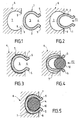
- FIGS 1 to 4 are schematic sectional views cross section showing successive process steps according to the invention.
- Figure 5 is a view similar to the previous ones, showing the device according to the invention at the end of the process.
- FIG. 1 shows in the rest state, that is to say in the absence of elastic deformation, a shell 1 intended to receive a bundle of electrical cables (not shown) in the process according to the invention.
- Shell 1 is a part extruded from polyethylene foam which can undergo elastic deformation both by bending of its wall and by compression in the thickness direction thereof, thanks to its porosity. It has a section transverse ⁇ -shaped, of which the main part 2, defining the body of the shell, is curved over more than one U-turn so as to delimit a cavity 3 communicating with the outside through a residual opening or slot 4.
- the part 2 is connected to two flanges 5 deviating from one of the other outward from the edges of the opening 4.
- Figure 1 also partially shows a cross 6 intended to extend transversely to the front of the passenger compartment of a motor vehicle to support the board on board and / or all or part of the cockpit equipment of the vehicle.
- the crosspiece 6 has a longitudinal housing 7 represented in the form of a groove which is made advantageously in a possibly extruded part constituting or belonging to the crosspiece.
- Wall of groove 7 is curved substantially in correspondence of the external surface of the body 2 of the shell 1, and the groove 7 communicates with the outside through an opening longitudinal 8 whose width is less than the width maximum of the groove.
- the shell is pushed 1 according to arrow F1 so as to make it enter the groove 7 through the opening 8.
- the size at rest of the body 2 in the direction of the width of opening 8 is greater than this width, by so that the edges 9 of the opening 8 rest on the body 2, reducing the width thereof by deformation elastic.
- the shell 1 relaxes and resumes its original shape insofar as the respective dimensions of the shell and of the groove 7 allow, a residual deformation may remain without affecting the function of the hull.
- Another way of proceeding consists in first mounting the beam in the hull, then the assembly thus obtained in the support.
- the final position is shown in figure 5.
- the beam 10 is housed in the cavity 3 and comes into contact with the shell 1 according to at least three generators, the shell being itself in contact with the wall of the groove 7 also according to at least three generators.
- This results in a beam-free positioning relative to the cross 6 in the plane of the figure, that is to say in a plane perpendicular to the longitudinal direction of the beam.
- this maintenance is further reinforced by radial tightening of the beam in the hull and of the hull in the groove, thanks to the elastic deformation of the shell. It is also possible to leave a clearance between the shell and beam, the foam wall of the shell avoiding beam noises.
- the wiring harness route is not necessarily straight. It can also be curvilinear and / or online broken, especially when the support itself is not straight.
- the housing 7 is then shaped according to the path desired, and the shell adapts to it by deformation elastic.
Abstract
Description
L'invention concerne un procédé et un dispositif pour envelopper un faisceau de câbles électriques et le fixer le long d'un support allongé, notamment pour l'alimentation électrique d'appareils et/ou la transmission de signaux électriques dans un véhicule automobile.The invention relates to a method and a device for wrap a bundle of electrical cables and secure it along an elongated support, especially for food electrical appliance and / or signal transmission electric vehicles.
L'expression "faisceau de câbles électriques" désigne un ensemble de câbles ou de fils électriques accolés ou regroupés les uns aux autres de manière à s'étendre côte à côte selon un trajet commun. Généralement, chaque câble ou fil est accolé aux autres sur une partie seulement de sa longueur, et s'en écarte sur au moins une autre partie de sa longueur pour atteindre des éléments à raccorder électriquement. La présente invention concerne plus particulièrement l'enveloppement et la fixation d'un ensemble de telles parties accolées de câbles ou fils.The term "wiring harness" means a set of cables or electric wires joined or grouped to each other so as to spread side by side along a common route. Generally, each cable or wire is joined to others on only part of its length, and deviates from it over at least one other part of its length to reach elements to be connected electrically. The present invention relates more particularly the wrapping and fixing of a set of such adjoining parts of cables or wires.
Dans les applications automobiles notamment, il est nécessaire d'envelopper les faisceaux de câbles, pour éviter que le frottement entre ceux-ci et des éléments voisins, dû aux vibrations et aux mouvements du véhicule, provoque un endommagement des câbles ou fils d'une part, et l'émission de bruit d'autre part. Cet enveloppement peut être réalisé au moyen de rubans adhésifs enroulés en hélice autour des fils de manière à les recouvrir au moins partiellement, et complètement par endroits. Une autre fonction des rubans adhésifs est de rendre les fils des faisceaux solidaires pour leur montage et leur tenue dans le véhicule. Ces rubans adhésifs peuvent coûter cher, et l'opération d'enrubannage être coûteuse en main-d'oeuvre. En outre, l'insonorisation obtenue n'est pas toujours entièrement satisfaisante.In automotive applications in particular, it is necessary wrap the cable harnesses to prevent the friction between them and neighboring elements, due to vibration and movement of the vehicle, causes damage to cables or wires on the one hand, and the emission noise on the other hand. This wrapping can be done by means of adhesive tapes wound in a helix around the wires so as to cover them at least partially, and completely in places. Another function of ribbons is to make the wires of the bundles united for mounting and holding in the vehicle. These ribbons adhesives can be expensive, and the wrapping operation be costly in labor. In addition, soundproofing obtained is not always entirely satisfactory.
Quant à la fixation du faisceau sur son support, qui est par exemple la traverse supportant le cockpit dans le cas d'un faisceau servant à raccorder des équipements du tableau de faisceau servant à raccorder des équipements du tableau de bord d'un véhicule, elle est réalisée par des agrafes métalliques ou plastiques réparties sur la longueur du faisceau. Ce mode de fixation est lui aussi relativement coûteux en main-d'oeuvre et n'assure pas une immobilisation parfaite du faisceau sur toute sa longueur.As for fixing the beam on its support, which is by example the cross supporting the cockpit in the case of a harness used to connect equipment to the switchboard harness used to connect equipment to the switchboard on board a vehicle, it is carried out by staples metallic or plastic spread over the length of the beam. This method of attachment is also relatively labor-intensive and does not provide immobilization perfect beam over its entire length.
Le but de l'invention est de remédier à ces inconvénients.The object of the invention is to remedy these drawbacks.
L'invention vise notamment un procédé du genre défini en introduction, et prévoit qu'on insère le faisceau dans une coque allongée en forme de canal déformable élastiquement, par une ouverture d'entrée longitudinale, la coque étant elle-même fixée au support dans une position où la largeur de ladite ouverture d'entrée est inférieure au diamètre du faisceau.The invention relates in particular to a method of the kind defined in introduction, and plans to insert the beam into a elongated shell in the form of an elastically deformable channel, by a longitudinal entry opening, the shell being itself fixed to the support in a position where the width of said inlet opening is less than the diameter of the beam.
Lorsque le diamètre du faisceau varie sur la longueur de la coque, la largeur de l'ouverture d'entrée est inférieure au diamètre maximal du faisceau.When the beam diameter varies over the length of the shell, the width of the inlet opening is less than maximum beam diameter.
Des caractéristiques optionnelles de l'invention, complémentaires ou alternatives, sont énoncées ci-après:
- On fixe la coque au support avant d'y insérer le faisceau. Ainsi la coque peut servir de support d'assemblage et de transport des fils ou câbles constituant le faisceau, dans les diverses configurations de celui-ci correspondant aux options du véhicule.
- On insère le faisceau dans la coque avant de fixer celle-ci au support.
- On fixe la coque au support en insérant celle-ci dans un logement allongé prévu dans le support, par une ouverture d'entrée longitudinale dont la largeur est inférieure au diamètre extérieur de la coque lorsque celle-ci entoure le faisceau.
- Ledit logement est prévu dans une partie extrudée du support.
- La coque présente deux rebords s'écartant l'un de l'autre vers l'extérieur à partir des bords de son ouverture d'entrée respectivement, propres à faciliter la dilatation élastique de l'ouverture lors de l'introduction du faisceau et/ou à protéger des parties de fils s'écartant de celui-ci à leur sortie du support.
- La coque est extrudée.
- La coque est en matériau cellulaire.
- La coque est en polyéthylène.
- The shell is fixed to the support before inserting the beam into it. Thus the shell can serve as a support for assembling and transporting the wires or cables constituting the bundle, in the various configurations thereof corresponding to the options of the vehicle.
- The beam is inserted into the shell before fixing it to the support.
- The shell is fixed to the support by inserting the latter into an elongated housing provided in the support, by a longitudinal entry opening whose width is less than the outside diameter of the shell when the latter surrounds the beam.
- Said housing is provided in an extruded part of the support.
- The shell has two flanges deviating from one another outward from the edges of its inlet opening respectively, capable of facilitating the elastic expansion of the opening when the beam is introduced and / or to protect parts of wires deviating therefrom when they exit from the support.
- The shell is extruded.
- The shell is made of cellular material.
- The shell is made of polyethylene.
L'invention a également pour objet un dispositif pour la mise en oeuvre du procédé tel que défini ci-dessus, comprenant un faisceau de câbles électriques, une coque allongée en forme de canal déformable élastiquement, propre à recevoir ledit faisceau par une ouverture d'entrée longitudinale, et des moyens de fixation de la coque le long d'un support allongé, dans une position où la largeur de ladite ouverture d'entrée est inférieure au diamètre du faisceau.The invention also relates to a device for the implementation of the method as defined above, comprising a bundle of electric cables, a shell elongated, clean, elastically deformable channel to receive said beam through an entrance opening longitudinal, and means for fixing the shell along an elongated support, in a position where the width of said inlet opening is less than the diameter of the beam.
Avantageusement, les moyens de fixation de la coque comprennent un logement allongé prévu dans le support, propre à recevoir la coque par une ouverture d'entrée longitudinale dont la largeur est inférieure au diamètre extérieur de la coque lorsque celle-ci entoure le faisceau.Advantageously, the means for fixing the shell comprise an elongated housing provided in the support, suitable for receive the shell through a longitudinal entry opening whose width is less than the outside diameter of the shell when it surrounds the beam.
Les caractéristiques et avantages de l'invention seront exposés plus en détail dans la description ci-après, en se référant aux dessins annexés. The characteristics and advantages of the invention will be described in more detail in the description below, in referring to the attached drawings.
Les figures 1 à 4 sont des vues schématiques en coupe transversale montrant des étapes successives du procédé selon l'invention.Figures 1 to 4 are schematic sectional views cross section showing successive process steps according to the invention.
La figure 5 est une vue analogue aux précédentes, montrant le dispositif selon l'invention à l'issue du procédé.Figure 5 is a view similar to the previous ones, showing the device according to the invention at the end of the process.
La figure 1 montre à l'état de repos, c'est-à-dire en
l'absence déformation élastique, une coque 1 destinée à
recevoir un faisceau de câbles électriques (non représenté)
dans le procédé selon l'invention. La coque 1 est une pièce
extrudée en mousse de polyéthylène pouvant subir une
déformation élastique aussi bien par flexion de sa paroi que
par compression dans la direction de l'épaisseur de celle-ci,
grâce à sa porosité. Elle présente une section
transversale en forme de Ω, dont la partie principale 2,
définissant le corps de la coque, est incurvée sur plus d'un
demi-tour de manière à délimiter une cavité 3 communiquant
avec l'extérieur par une ouverture résiduelle ou fente 4. La
partie 2 se raccorde à deux rebords 5 s'écartant l'un de
l'autre vers l'extérieur à partir des bords de l'ouverture
4.FIG. 1 shows in the rest state, that is to say in
the absence of elastic deformation, a
La figure 1 montre également en partie une traverse 6
destinée à s'étendre transversalement à l'avant de l'habitacle
d'un véhicule automobile pour supporter la planche de
bord et/ou tout ou partie des équipements du cockpit du
véhicule. La traverse 6 présente un logement longitudinal 7
représenté sous la forme d'une rainure qui est réalisée
avantageusement dans une pièce éventuellement extrudée
constituant la traverse ou appartenant à celle-ci. La paroi
de la rainure 7 est incurvée sensiblement en correspondance
de la surface externe du corps 2 de la coque 1, et la
rainure 7 communique avec l'extérieur par une ouverture
longitudinale 8 dont la largeur est inférieure à la largeur
maximale de la rainure. Figure 1 also partially shows a
Dans l'étape du procédé représentée sur la figure 1, on
présente la coque 1 en regard de l'ouverture 8, l'ouverture
4 étant placée à l'opposé de cette dernière.In the process step shown in Figure 1, we
presents the
Dans l'étape représentée sur la figure 2, on pousse la coque
1 selon la flèche F1 de manière à la faire pénétrer dans la
rainure 7 à travers l'ouverture 8. Dans l'exemple illustré,
l'encombrement au repos du corps 2 dans la direction de la
largeur de l'ouverture 8 est supérieur à cette largeur, de
sorte que les bords 9 de l'ouverture 8 s'appuient sur le
corps 2, réduisant la largeur de celui-ci par déformation
élastique. À la fin de l'introduction, comme montré sur la
figure 3, la coque 1 se détend et reprend sa forme initiale
dans la mesure où les dimensions respectives de la coque et
de la rainure 7 le permettent, une déformation résiduelle
pouvant subsister sans nuire à la fonction de la coque.In the step shown in Figure 2, the shell is pushed
1 according to arrow F1 so as to make it enter the
Dans l'étape représentée sur la figure 4, on présente le
faisceau de câbles 10 en regard de l'ouverture 4 et on le
pousse selon la flèche F2 pour le faire pénétrer à l'intérieur
de la coque. La poussée du faisceau écarte les rebords
5 par déformation élastique, et l'épaisseur de paroi de la
coque est localement réduite si nécessaire, grâce à la
porosité de la coque, lors du passage du faisceau dans son
diamètre maximal à travers l'ouverture 8.In the step shown in Figure 4, we present the
Comme évoqué plus haut, une autre manière de procéder consiste à monter d'abord le faisceau dans la coque, puis l'ensemble ainsi obtenu dans le support.As mentioned above, another way of proceeding consists in first mounting the beam in the hull, then the assembly thus obtained in the support.
La position finale est montrée sur la figure 5. Le faisceau
10 est logé dans la cavité 3 et vient en contact avec la
coque 1 selon au moins trois génératrices, la coque étant
elle-même en contact avec la paroi de la rainure 7 également
selon au moins trois génératrices. Il en résulte un
positionnement sans jeu du faisceau par rapport à la
traverse 6 dans le plan de la figure, c'est-à-dire dans un
plan perpendiculaire à la direction longitudinale du
faisceau. De préférence, ce maintien est encore renforcé par
un serrage radial du faisceau dans la coque et de la coque
dans la rainure, grâce à la déformation élastique de la
coque. Il est également possible de laisser un jeu entre la
coque et le faisceau, la paroi en mousse de la coque évitant
les bruits du faisceau.The final position is shown in figure 5. The
Le trajet du faisceau de câbles n'est pas nécessairement
rectiligne. Il peut également être curviligne et/ou en ligne
brisée, notamment lorsque le support lui-même n'est pas
rectiligne. Le logement 7 est alors conformé selon le trajet
souhaité, et la coque s'adapte à celui-ci par déformation
élastique.The wiring harness route is not necessarily
straight. It can also be curvilinear and / or online
broken, especially when the support itself is not
straight. The
Bien qu'on ait décrit l'utilisation d'une coque en mousse,
c'est-à-dire à paroi poreuse, il est également possible
d'utiliser une coque à paroi pleine. Dans ce cas, la diminution
d'épaisseur mentionnée à propos de la figure 4, si elle
est nécessaire, c'est-à-dire si l'épaisseur au repos de la
paroi est supérieure à la moitié de la différence entre la
largeur de l'ouverture 8 et le diamètre maximal du faisceau
10, est obtenue par déplacement de matière parallèlement à
la direction d'introduction du faisceau. Par ailleurs, dans
le cas où la largeur de la coque n'est pas supérieure, au
repos, à la largeur de l'ouverture 8, cette largeur est
augmentée par déformation élastique, lorsque le faisceau 10
est introduit, pour empêcher la coque et le faisceau de
sortir du logement 7.Although the use of a foam shell has been described,
that is to say with a porous wall, it is also possible
use a full-walled hull. In this case, the decrease
of thickness mentioned in connection with Figure 4, if it
is necessary, i.e. if the thickness at rest of the
wall is more than half the difference between the
width of
Claims (10)
Applications Claiming Priority (2)
| Application Number | Priority Date | Filing Date | Title |
|---|---|---|---|
| FR0016796A FR2818816B1 (en) | 2000-12-21 | 2000-12-21 | DEVICE FOR ENCLOSING AND FIXING A BEAM OF ELECTRICAL CABLES |
| FR0016796 | 2000-12-21 |
Publications (1)
| Publication Number | Publication Date |
|---|---|
| EP1216887A1 true EP1216887A1 (en) | 2002-06-26 |
Family
ID=8858020
Family Applications (1)
| Application Number | Title | Priority Date | Filing Date |
|---|---|---|---|
| EP01128891A Withdrawn EP1216887A1 (en) | 2000-12-21 | 2001-12-05 | Device for wrapping and fastening an electric wire harness |
Country Status (4)
| Country | Link |
|---|---|
| US (1) | US6688679B2 (en) |
| EP (1) | EP1216887A1 (en) |
| JP (1) | JP2002305834A (en) |
| FR (1) | FR2818816B1 (en) |
Cited By (1)
| Publication number | Priority date | Publication date | Assignee | Title |
|---|---|---|---|---|
| WO2022142055A1 (en) * | 2020-12-29 | 2022-07-07 | 罗森伯格技术有限公司 | Cable fixing device and antenna |
Families Citing this family (14)
| Publication number | Priority date | Publication date | Assignee | Title |
|---|---|---|---|---|
| KR100461418B1 (en) * | 2002-10-02 | 2004-12-10 | 현대자동차주식회사 | a mounting structure of power steering return tube |
| US7557298B2 (en) * | 2002-10-14 | 2009-07-07 | World Properties, Inc. | Laminated bus bar assembly |
| EP1498651A3 (en) * | 2003-07-17 | 2006-04-12 | Peter Brandes | Fastening device |
| DE102005004605B4 (en) * | 2005-02-01 | 2009-03-05 | Lisa Dräxlmaier GmbH | Crossmember module for a motor vehicle |
| US20080029656A1 (en) * | 2006-07-20 | 2008-02-07 | John Feehan | Guide for cords, cables and wires |
| US8523824B2 (en) * | 2008-07-08 | 2013-09-03 | Vascular Solutions, Inc. | Guidewire and catheter management device |
| US20100006738A1 (en) * | 2008-07-08 | 2010-01-14 | Teirstein Paul S | Guide wire and catheter management device |
| US8011720B2 (en) * | 2009-04-09 | 2011-09-06 | Toyota Motor Engineering & Manufacturing North America, Inc. | Apparatus to aid in the assembly of cables and electrical components |
| JP5326171B2 (en) * | 2009-08-31 | 2013-10-30 | ポップリベット・ファスナー株式会社 | Long member holder |
| US9638085B2 (en) | 2013-01-18 | 2017-05-02 | Cnh Industrial America Llc | Diesel exhaust fluid tank for an off-road vehicle |
| KR101801669B1 (en) * | 2016-09-13 | 2017-11-28 | 린나이코리아 주식회사 | Electronic equipment wire fixed bush |
| JP2019089398A (en) * | 2017-11-13 | 2019-06-13 | 矢崎総業株式会社 | Electric wire arrangement structure and vehicle circuit body |
| US11791064B2 (en) | 2018-12-17 | 2023-10-17 | Sumitomo Wiring Systems, Ltd. | Wiring member and attachment structure of wiring member |
| US11266275B1 (en) * | 2019-08-09 | 2022-03-08 | Interdesign, Inc. | Shower caddy grip hook and accessory grip lock |
Citations (6)
| Publication number | Priority date | Publication date | Assignee | Title |
|---|---|---|---|---|
| DE3031833A1 (en) * | 1980-08-23 | 1982-05-06 | Felten & Guilleaume Carlswerk AG, 5000 Köln | Continuous attachment element for parallel cables and conductors - has continuous longitudinal ducts some with wall slits |
| GB2203598A (en) * | 1987-01-17 | 1988-10-19 | Honda Motor Co Ltd | Structure for securing a wire harness assembly |
| EP0349376A1 (en) * | 1988-06-28 | 1990-01-03 | Legrand | Cable-guide |
| DE29607671U1 (en) * | 1996-04-27 | 1996-07-25 | Zipper Technik Gmbh | Fastening element for a tubular casing |
| US5879047A (en) * | 1996-08-08 | 1999-03-09 | Yazaki Corporation | Wire harness installation structure for vehicle door |
| US6092854A (en) * | 1997-01-08 | 2000-07-25 | Cascade Engineering, Inc. | Mat with integral wire harness fastener and channel |
-
2000
- 2000-12-21 FR FR0016796A patent/FR2818816B1/en not_active Expired - Fee Related
-
2001
- 2001-12-04 US US10/000,491 patent/US6688679B2/en not_active Expired - Fee Related
- 2001-12-05 EP EP01128891A patent/EP1216887A1/en not_active Withdrawn
- 2001-12-20 JP JP2001387018A patent/JP2002305834A/en active Pending
Patent Citations (6)
| Publication number | Priority date | Publication date | Assignee | Title |
|---|---|---|---|---|
| DE3031833A1 (en) * | 1980-08-23 | 1982-05-06 | Felten & Guilleaume Carlswerk AG, 5000 Köln | Continuous attachment element for parallel cables and conductors - has continuous longitudinal ducts some with wall slits |
| GB2203598A (en) * | 1987-01-17 | 1988-10-19 | Honda Motor Co Ltd | Structure for securing a wire harness assembly |
| EP0349376A1 (en) * | 1988-06-28 | 1990-01-03 | Legrand | Cable-guide |
| DE29607671U1 (en) * | 1996-04-27 | 1996-07-25 | Zipper Technik Gmbh | Fastening element for a tubular casing |
| US5879047A (en) * | 1996-08-08 | 1999-03-09 | Yazaki Corporation | Wire harness installation structure for vehicle door |
| US6092854A (en) * | 1997-01-08 | 2000-07-25 | Cascade Engineering, Inc. | Mat with integral wire harness fastener and channel |
Cited By (1)
| Publication number | Priority date | Publication date | Assignee | Title |
|---|---|---|---|---|
| WO2022142055A1 (en) * | 2020-12-29 | 2022-07-07 | 罗森伯格技术有限公司 | Cable fixing device and antenna |
Also Published As
| Publication number | Publication date |
|---|---|
| JP2002305834A (en) | 2002-10-18 |
| US6688679B2 (en) | 2004-02-10 |
| US20020079122A1 (en) | 2002-06-27 |
| FR2818816A1 (en) | 2002-06-28 |
| FR2818816B1 (en) | 2003-10-03 |
Similar Documents
| Publication | Publication Date | Title |
|---|---|---|
| EP1216887A1 (en) | Device for wrapping and fastening an electric wire harness | |
| EP2115837B1 (en) | Attachment device for a yarn cable track | |
| FR2888683A1 (en) | ECONESS FOR CONNECTING CABLE TRUNCTIONS | |
| EP1463904B1 (en) | Protective sheath reclosable by overlapping and use thereof | |
| EP0978915B1 (en) | Cableway | |
| WO2020038701A1 (en) | Assembly for protecting and securing a wiring harness | |
| FR2880401A1 (en) | DEVICE FOR FIXING ELONGATE ELEMENTS TO A STRUCTURE | |
| EP0891897B1 (en) | Flexible protective sheath for ensuring the passage between two installation parts such as an automotive vehicle | |
| EP1376798A1 (en) | Conduit meshsupport | |
| FR2734218A1 (en) | Fixing device for fixing cable bundle to part of motor vehicle body | |
| EP0706915B1 (en) | Mounting device for wire harness | |
| EP0797281A1 (en) | Process and assembly for mounting tightly a resilient tubular covering on an element | |
| FR2882198A1 (en) | Electric cable connecting device for e.g. car, has ring shape rigid insert housed in one of two end parts of body and assembled after molding, and notches symmetrically arranged on both sides of insert, where end parts have sealing lips | |
| FR2884579A1 (en) | Wall e.g. bulkhead, ring for vehicle, has cylindrical body, to be inserted in wall opening, formed of bellows, each presenting two extensible parts, where body has, at ends, rim and collar carried against respective sides of wall | |
| EP0686780B1 (en) | Mounting fitting for control cable | |
| FR3002090A1 (en) | System for providing watertight passage for pipes in e.g. electric or hybrid motor vehicle, has blocking head to exert support force on segments by driving head in position folded up towards support portion when rod is in fixed position | |
| EP3947046B1 (en) | Device for the sealed leadthrough of a cable sheath through an opening of a motor vehicle bulkhead | |
| FR3072153B1 (en) | DEVICE FOR FIXING A CORD TO A WALL | |
| FR2751048A1 (en) | Exhaust Pipe Articluated support for Cars | |
| FR2623857A1 (en) | Fixing device for tubing or the like | |
| EP0767468B1 (en) | Extensible and compressible electrical coupling harness | |
| FR2826091A1 (en) | Structured grommet seal passing wires through bulkhead, includes annular ring with first and second sets of retention tabs resting on opposite faces of wall. | |
| EP4046876A1 (en) | Accoustic grommet | |
| FR3124141A1 (en) | System for fixing connectors to a dashboard cross member. | |
| FR2793082A1 (en) | SEALING GASKET FOR A WALL PASSAGE AND ASSEMBLY OBTAINED WITH THIS GASKET |
Legal Events
| Date | Code | Title | Description |
|---|---|---|---|
| PUAI | Public reference made under article 153(3) epc to a published international application that has entered the european phase |
Free format text: ORIGINAL CODE: 0009012 |
|
| AK | Designated contracting states |
Kind code of ref document: A1 Designated state(s): AT BE CH CY DE DK ES FI FR GB GR IE IT LI LU MC NL PT SE TR |
|
| AX | Request for extension of the european patent |
Free format text: AL;LT;LV;MK;RO;SI |
|
| 17P | Request for examination filed |
Effective date: 20021216 |
|
| AKX | Designation fees paid |
Designated state(s): DE ES GB IT |
|
| 17Q | First examination report despatched |
Effective date: 20031104 |
|
| STAA | Information on the status of an ep patent application or granted ep patent |
Free format text: STATUS: THE APPLICATION IS DEEMED TO BE WITHDRAWN |
|
| 18D | Application deemed to be withdrawn |
Effective date: 20050922 |