EP1216875A2 - Power distribution apparatus for a four-wheel drive vehicle - Google Patents
Power distribution apparatus for a four-wheel drive vehicle Download PDFInfo
- Publication number
- EP1216875A2 EP1216875A2 EP01130463A EP01130463A EP1216875A2 EP 1216875 A2 EP1216875 A2 EP 1216875A2 EP 01130463 A EP01130463 A EP 01130463A EP 01130463 A EP01130463 A EP 01130463A EP 1216875 A2 EP1216875 A2 EP 1216875A2
- Authority
- EP
- European Patent Office
- Prior art keywords
- gear
- oil pressure
- plate clutch
- hydraulic multi
- pressure control
- Prior art date
- Legal status (The legal status is an assumption and is not a legal conclusion. Google has not performed a legal analysis and makes no representation as to the accuracy of the status listed.)
- Granted
Links
- 239000003921 oil Substances 0.000 claims abstract description 98
- 230000005540 biological transmission Effects 0.000 claims abstract description 50
- 230000007246 mechanism Effects 0.000 claims abstract description 43
- 239000010720 hydraulic oil Substances 0.000 claims abstract description 10
- 238000012546 transfer Methods 0.000 claims description 49
- 230000008859 change Effects 0.000 claims description 4
- 230000010349 pulsation Effects 0.000 abstract description 3
- 238000010276 construction Methods 0.000 description 7
- 238000012423 maintenance Methods 0.000 description 7
- 230000001276 controlling effect Effects 0.000 description 5
- 239000012530 fluid Substances 0.000 description 5
- 230000004308 accommodation Effects 0.000 description 3
- 230000015572 biosynthetic process Effects 0.000 description 2
- 230000008878 coupling Effects 0.000 description 2
- 238000010168 coupling process Methods 0.000 description 2
- 238000005859 coupling reaction Methods 0.000 description 2
- 238000013461 design Methods 0.000 description 2
- 238000010586 diagram Methods 0.000 description 2
- 230000001050 lubricating effect Effects 0.000 description 2
- 239000010687 lubricating oil Substances 0.000 description 2
- 238000004519 manufacturing process Methods 0.000 description 2
- 230000001105 regulatory effect Effects 0.000 description 2
- 238000004891 communication Methods 0.000 description 1
- 239000000470 constituent Substances 0.000 description 1
- 239000000446 fuel Substances 0.000 description 1
- 238000009499 grossing Methods 0.000 description 1
- 238000002347 injection Methods 0.000 description 1
- 239000007924 injection Substances 0.000 description 1
- 238000009434 installation Methods 0.000 description 1
- 230000004048 modification Effects 0.000 description 1
- 238000012986 modification Methods 0.000 description 1
- 230000000717 retained effect Effects 0.000 description 1
- 238000007789 sealing Methods 0.000 description 1
Images


Classifications
-
- F—MECHANICAL ENGINEERING; LIGHTING; HEATING; WEAPONS; BLASTING
- F16—ENGINEERING ELEMENTS AND UNITS; GENERAL MEASURES FOR PRODUCING AND MAINTAINING EFFECTIVE FUNCTIONING OF MACHINES OR INSTALLATIONS; THERMAL INSULATION IN GENERAL
- F16H—GEARING
- F16H57/00—General details of gearing
- F16H57/04—Features relating to lubrication or cooling or heating
- F16H57/0434—Features relating to lubrication or cooling or heating relating to lubrication supply, e.g. pumps; Pressure control
-
- B—PERFORMING OPERATIONS; TRANSPORTING
- B60—VEHICLES IN GENERAL
- B60K—ARRANGEMENT OR MOUNTING OF PROPULSION UNITS OR OF TRANSMISSIONS IN VEHICLES; ARRANGEMENT OR MOUNTING OF PLURAL DIVERSE PRIME-MOVERS IN VEHICLES; AUXILIARY DRIVES FOR VEHICLES; INSTRUMENTATION OR DASHBOARDS FOR VEHICLES; ARRANGEMENTS IN CONNECTION WITH COOLING, AIR INTAKE, GAS EXHAUST OR FUEL SUPPLY OF PROPULSION UNITS IN VEHICLES
- B60K17/00—Arrangement or mounting of transmissions in vehicles
- B60K17/02—Arrangement or mounting of transmissions in vehicles characterised by arrangement, location, or kind of clutch
-
- B—PERFORMING OPERATIONS; TRANSPORTING
- B60—VEHICLES IN GENERAL
- B60K—ARRANGEMENT OR MOUNTING OF PROPULSION UNITS OR OF TRANSMISSIONS IN VEHICLES; ARRANGEMENT OR MOUNTING OF PLURAL DIVERSE PRIME-MOVERS IN VEHICLES; AUXILIARY DRIVES FOR VEHICLES; INSTRUMENTATION OR DASHBOARDS FOR VEHICLES; ARRANGEMENTS IN CONNECTION WITH COOLING, AIR INTAKE, GAS EXHAUST OR FUEL SUPPLY OF PROPULSION UNITS IN VEHICLES
- B60K17/00—Arrangement or mounting of transmissions in vehicles
- B60K17/34—Arrangement or mounting of transmissions in vehicles for driving both front and rear wheels, e.g. four wheel drive vehicles
-
- B—PERFORMING OPERATIONS; TRANSPORTING
- B60—VEHICLES IN GENERAL
- B60K—ARRANGEMENT OR MOUNTING OF PROPULSION UNITS OR OF TRANSMISSIONS IN VEHICLES; ARRANGEMENT OR MOUNTING OF PLURAL DIVERSE PRIME-MOVERS IN VEHICLES; AUXILIARY DRIVES FOR VEHICLES; INSTRUMENTATION OR DASHBOARDS FOR VEHICLES; ARRANGEMENTS IN CONNECTION WITH COOLING, AIR INTAKE, GAS EXHAUST OR FUEL SUPPLY OF PROPULSION UNITS IN VEHICLES
- B60K17/00—Arrangement or mounting of transmissions in vehicles
- B60K17/34—Arrangement or mounting of transmissions in vehicles for driving both front and rear wheels, e.g. four wheel drive vehicles
- B60K17/344—Arrangement or mounting of transmissions in vehicles for driving both front and rear wheels, e.g. four wheel drive vehicles having a transfer gear
- B60K17/346—Arrangement or mounting of transmissions in vehicles for driving both front and rear wheels, e.g. four wheel drive vehicles having a transfer gear the transfer gear being a differential gear
-
- B—PERFORMING OPERATIONS; TRANSPORTING
- B60—VEHICLES IN GENERAL
- B60K—ARRANGEMENT OR MOUNTING OF PROPULSION UNITS OR OF TRANSMISSIONS IN VEHICLES; ARRANGEMENT OR MOUNTING OF PLURAL DIVERSE PRIME-MOVERS IN VEHICLES; AUXILIARY DRIVES FOR VEHICLES; INSTRUMENTATION OR DASHBOARDS FOR VEHICLES; ARRANGEMENTS IN CONNECTION WITH COOLING, AIR INTAKE, GAS EXHAUST OR FUEL SUPPLY OF PROPULSION UNITS IN VEHICLES
- B60K17/00—Arrangement or mounting of transmissions in vehicles
- B60K17/34—Arrangement or mounting of transmissions in vehicles for driving both front and rear wheels, e.g. four wheel drive vehicles
- B60K17/348—Arrangement or mounting of transmissions in vehicles for driving both front and rear wheels, e.g. four wheel drive vehicles having differential means for driving one set of wheels, e.g. the front, at one speed and the other set, e.g. the rear, at a different speed
- B60K17/35—Arrangement or mounting of transmissions in vehicles for driving both front and rear wheels, e.g. four wheel drive vehicles having differential means for driving one set of wheels, e.g. the front, at one speed and the other set, e.g. the rear, at a different speed including arrangements for suppressing or influencing the power transfer, e.g. viscous clutches
-
- B—PERFORMING OPERATIONS; TRANSPORTING
- B60—VEHICLES IN GENERAL
- B60K—ARRANGEMENT OR MOUNTING OF PROPULSION UNITS OR OF TRANSMISSIONS IN VEHICLES; ARRANGEMENT OR MOUNTING OF PLURAL DIVERSE PRIME-MOVERS IN VEHICLES; AUXILIARY DRIVES FOR VEHICLES; INSTRUMENTATION OR DASHBOARDS FOR VEHICLES; ARRANGEMENTS IN CONNECTION WITH COOLING, AIR INTAKE, GAS EXHAUST OR FUEL SUPPLY OF PROPULSION UNITS IN VEHICLES
- B60K23/00—Arrangement or mounting of control devices for vehicle transmissions, or parts thereof, not otherwise provided for
- B60K23/08—Arrangement or mounting of control devices for vehicle transmissions, or parts thereof, not otherwise provided for for changing number of driven wheels, for switching from driving one axle to driving two or more axles
- B60K23/0808—Arrangement or mounting of control devices for vehicle transmissions, or parts thereof, not otherwise provided for for changing number of driven wheels, for switching from driving one axle to driving two or more axles for varying torque distribution between driven axles, e.g. by transfer clutch
-
- B—PERFORMING OPERATIONS; TRANSPORTING
- B60—VEHICLES IN GENERAL
- B60K—ARRANGEMENT OR MOUNTING OF PROPULSION UNITS OR OF TRANSMISSIONS IN VEHICLES; ARRANGEMENT OR MOUNTING OF PLURAL DIVERSE PRIME-MOVERS IN VEHICLES; AUXILIARY DRIVES FOR VEHICLES; INSTRUMENTATION OR DASHBOARDS FOR VEHICLES; ARRANGEMENTS IN CONNECTION WITH COOLING, AIR INTAKE, GAS EXHAUST OR FUEL SUPPLY OF PROPULSION UNITS IN VEHICLES
- B60K5/00—Arrangement or mounting of internal-combustion or jet-propulsion units
- B60K5/04—Arrangement or mounting of internal-combustion or jet-propulsion units with the engine main axis, e.g. crankshaft axis, transversely to the longitudinal centre line of the vehicle
-
- Y—GENERAL TAGGING OF NEW TECHNOLOGICAL DEVELOPMENTS; GENERAL TAGGING OF CROSS-SECTIONAL TECHNOLOGIES SPANNING OVER SEVERAL SECTIONS OF THE IPC; TECHNICAL SUBJECTS COVERED BY FORMER USPC CROSS-REFERENCE ART COLLECTIONS [XRACs] AND DIGESTS
- Y10—TECHNICAL SUBJECTS COVERED BY FORMER USPC
- Y10T—TECHNICAL SUBJECTS COVERED BY FORMER US CLASSIFICATION
- Y10T74/00—Machine element or mechanism
- Y10T74/19—Gearing
- Y10T74/19023—Plural power paths to and/or from gearing
- Y10T74/19074—Single drive plural driven
- Y10T74/19112—Aligned
- Y10T74/19116—Vehicle
Definitions
- the present invention relates to a power distribution apparatus for a four-wheel drive vehicle.
- the power distribution apparatus efficiently distributes drive force from a transmission, which is connected to a transversely laid out engine, to front and rear wheels via a hydraulic multi-plate clutch that is disposed together with required constituent components thereof efficiently.
- a distribution of a predetermined power to front and rear wheels is usually accomplished by controlling a clamping force of a hydraulic multi-plate clutch as a transfer clutch.
- a clamping force of the hydraulic multi-plate clutch it is required to have at least an oil pressure control portion having a control valve for varying the clamping force of the hydraulic multi-plate clutch, and an oil pressure source for generating an oil pressure for the hydraulic multi-plate clutch.
- the engine is arranged on a front side of a vehicle body in order to secure a passenger space as wide as possible in the vehicle body.
- a transversal arrangement is adopted in such a manner that an output shaft of the engine is disposed in parallel with a wheel shaft. This construction also applies to a four-wheel drive vehicle.
- Japanese Unexamined Patent Publication No. Hei. 6-92156 discloses a construction in which a hydraulic multi-plate clutch distributes to the rear wheel side, a predetermined drive force inputted into a differential from a transmission.
- the hydraulic multi-plate clutch is mounted on a front drive shaft beside a differential for the front wheels.
- Japanese Patent Unexamined Publication No. Hei 6-107019 discloses a four-wheel drive vehicle having a hydraulic multi-plate clutch.
- the hydraulic multi-plate clutch that distributes a drive force to the rear wheel side is provided between a rear end of a gear shaft extending rearwards from one of a pair of direction changing gears for changing a drive force transmission direction to the rear wheel side and a distal end of a propeller shaft.
- the diameter of the clutch portion of the transfer unit is increased longitudinally and this leads to the enlargement of the transfer unit.
- this enlarged portion of the clutch portion typically runs across the vehicle body chassis structure such as a steering gearbox and a cross member thereabove or therebelow. Therefore in order to maintain a good positional relationship between those members and the transfer unit, the steering gearbox needs to be re-located and the cross member needs to be curved, thus making the vehicle structure complex.
- the present invention was made in view of the above problems and objects thereof are to provide a power distribution apparatus for a four-wheel drive vehicle which is compact in size, which is subject to no limitations as to the apparatus' position relative to the vehicle body structure such as the steering gearbox and the cross member, which can secure with ease the oil-tightness for hydraulic fluid for operating the hydraulic multi-plate clutch, which is superior in providing good productivity of transmissions and transfer units and serviceability thereof for maintenance after they are installed, and which is easy to be installed on the vehicle.
- a power distribution apparatus for a four-wheel drive vehicle comprising: a transversely laid out front engine outputting a drive force via a transmission coupled thereto; a transfer unit including: a pair of direction changing gears for changing a transmission direction of the drive force to a rear direction of the vehicle; a first gear provided on a gear shaft extending rearward from one of the pair of direction changing gears; a second gear adapted to mesh with the first gear so as to change the drive force transmission direction in parallel with the rear direction; an output shaft adapted to rotatably pass through an axial center of a gear shaft of the second gear so as to output the drive force to the rear direction of the vehicle; a hydraulic multi-plate clutch for variably transmitting torque between the gear shaft of the second gear and the output shaft; and an oil pressure control mechanism integrally incorporating at least an oil pressure source for generating a hydraulic oil pressure for the hydraulic multi-plate clutch and an oil pressure control portion for controlling the
- a power distribution apparatus for a four-wheel drive vehicle as set forth in the first aspect of the present invention, wherein the hydraulic multi-plate clutch and the oil pressure control mechanism portion are accommodated and disposed independently and oil-tightly relative to a gear mechanism portion.
- a power distribution apparatus for a four-wheel drive vehicle as set forth in the first or second aspect of the present invention, wherein an accommodation chamber for accommodating therein the hydraulic multi-plate clutch has an opening in one side thereof, and where a member for closing the opening is the oil pressure control mechanism portion.
- the transmission direction of the drive force from the transmission coupled to the transversely laid out front engine is changed to the rear by way of the pair of direction changing gears .
- the drive force is transmitted from the first gear, which is provided on the gear shaft extending to the rear from one of the pair of direction changing gears, to the second gear, so that the transmission direction of the drive force is changed in a parallel.
- the control valve in the oil pressure control portion is actuated so that the predetermined oil pressure is applied to the hydraulic multi-plate clutch by the hydraulic fluid, the hydraulic multi-plate clutch is clamped.
- the transfer unit can be constructed and laid out in a compact manner in both transverse and longitudinal directions.
- the hydraulic multi-plate clutch is subject to little positional limitation relative to the vehicle body structure such as the steering gearbox and the cross member, thus providing superior mounting properties.
- the oil pressure control portion and the oil pressure source may be integrally coupled together disposed at the substantially horizontal side position on the hydraulic multi-plate clutch as the oil pressure control mechanism portion.
- the oil pressure control mechanism portion is constructed by integrally coupling the oil pressure control portion and the oil pressure source, as with the power distribution apparatus for a four-wheel drive vehicle according to the second aspect of the present invention, the hydraulic multi-plate clutch and the oil pressure control mechanism portion are accommodated and disposed independently and in an oil-tight manner relative to the gear mechanism portion, whereby the oil-tightness can easily be secured relative to the other transmission oil and the like.
- the oil pressure control mechanism portion is constructed by integrally coupling the oil pressure control portion and the oil pressure source, there is no need to form oil paths or the like on the transmission side. Therefore, the transmission can be commonly used for both two-wheel drive vehicles and four-wheel drive vehicles. Moreover, the productivity of transfer units and the serviceability thereof for maintenance after installation can be improved.
- the power distribution apparatus for a four-wheel drive vehicle as set forth in the first or second aspect of the present invention, wherein the transfer unit further includes an accommodation chamber for accommodating the hydraulic multi-plate clutch therein, the accommodation chamber has an opening in one side thereof, and where the opening is closed by the oil pressure control mechanism portion.
- the power distribution apparatus can be made more space efficient and the serviceability for maintenance can also be improved.
- Figs. 1 to 3 show an embodiment according to the present invention.
- Fig. 1 is a sectional view of a main part of a transfer unit
- Fig. 2 is a schematic explanatory view of a positional relationship of an oil pressure control circuit and the like as viewed from the direction of a front wheel shaft
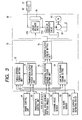
- Fig. 3 is a block diagram explaining the function of power distribution control and the construction of an oil pressure control mechanism portion.
- reference numeral 1 denotes a transversely laid out engine in a front engine compartment of a vehicle, and a transmission 2 coupled with the engine 1 is disposed on an output shaft of the engine 1 in the left-hand side of the hood.
- a transfer unit 3 is integrally provided with the engine 1 and the transmission 2 and disposed at the rear part of the engine 1 and the transmission 2, whereby a drive force outputted from the engine 1 is subject to a predetermined speed change at the transmission and is then distributed to a rear wheel side by the transfer unit 3.
- the transfer unit 3 is disposed to the rear of the transmission 2 in such a manner as to be offset toward the engine 1 side.
- the transfer unit 3 is constituted by a gear mechanism portion 7 for transmitting power, which is transmitted to a differential case 6 of a front differential 5 for transmitting drive force from the transmission 2 to a front wheel side and to the rear wheel side.
- the transfer unit 3 is further constituted by a hydraulic multi-plate clutch 8 acting as a transfer clutch for continuously variably controlling the distribution of the drive force to the rear wheel side in accordance with running conditions and driving conditions.
- the front differential 5 is integrally accommodated in a differential accommodating compartment 10.
- the gear mechanism 7 is integrally accommodated in a gear accommodating compartment 11 formed in a transfer case 9.
- the hydraulic multi-plate clutch 8 is integrally accommodated in a clutch accommodating compartment 12 formed in the transfer case 9.
- the front differential 5 comprises a final gear 17 around the outer circumference of the differential case 6.
- This final gear 17 is adapted to mesh with a drive gear 16 fixedly provided on an output shaft 15 of the transmission 2.
- the front differential 5 is a known bevel gear type differential and is constituted by a pair of differential pinions 21, 21 and left and right side gears 22L, 22R.
- the pair of differential pinions 21, 21 are rotatably supported on a pinion shaft 20 fixedly provided within the differential case 6.
- the left and right side gears 22L, 22R are adapted to mesh with the differential pinions 21, 21.
- left and right front wheel drive shafts 25L, 25R are fitted in the left and right side gears 22L, 22R via tube portions 26L, 26R extending transversely from the differential case 6.
- the drive force transmitted to the side gears 22L, 22R from the differential case 6 via the differential pinions 21, 21 is then transmitted to left and right front wheels via the drive shafts 25L, 25R of the left and right front wheels.
- the right side tube portion 26R of the differential case 6 is extended to the interior of the gear accommodating compartment 11.
- the drive force is transmitted to the gear mechanism portion 7 via the extended right side tube portion 26R.
- An oil seal 27 retained on the transfer case 9 is slidably connected to the outer circumference of the right side tube portion 26R at an intermediate position along the length thereof. Therefore, the oil-tightness within the differential accommodating compartment 10 and the gear accommodating compartment 11 is maintained. Note that in the case where lubricating oil for lubricating the front differential 5 and lubricating oil for lubricating the gear mechanism portion 7 are the same, the oil seal 27 may be omitted.
- the gear mechanism portion 7 comprises a pair of direction changing gears (first and second direction changing gears) 30, 31 comprising in turn hypoid gears and a pair of gears (first and second gears) 32, 33 comprising in turn helical gears.
- the first direction changing gear 30 is fixedly provided on a hollow transfer shaft 34 that is spline-fitted on the outer circumference of a distal end of the tube portion 26R.
- the second direction changing gear 31 meshes with the first direction changing gear 30 to thereby change the transmission direction of the drive force to the rear.
- a gear shaft (a pinion shaft) 31a of the second direction changing gear 31 extends rearwardly.
- the first gear 32 is spline fitted on a rear end of this pinion shaft 31a.
- the second gear 33 meshes with the first gear 32 at a right side position of the first gear 32.
- a gear shaft 33a of the second gear 33 is formed hollow, and an output shaft 35 for outputting the drive force to the rear is allowed to rotatably pass through the hollow gear shaft 33a.
- the output shaft 35 is clamped to be freely disengaged with transfer clutch torque.
- the transfer clutch torque is set by a drive force distribution control portion 70, which will be described later, and imparted by an oil pressure control mechanism portion 50 via the gear shaft 33a of the second gear 33 and the hydraulic multi-plate clutch 8.
- the hydraulic multi-plate clutch 8 may be a torque transmission capacity variable transfer clutch.
- the clutch accommodating compartment 12 for accommodating the hydraulic multi-plate clutch 8 is partitioned and formed on the axial center of the output shaft 35 on the engine 1 side ahead of the second gear 33.
- the distal ends of the gear shaft 33a and the output shaft 35 extend into this clutch accommodating compartment 12.
- a pair of oil seals 36, 36 are held in the transfer case 9 and a housing supporting the gears 32, 33.
- the pair of oil seals 36, 36 are brought into slidable contact with the gear shaft 33a at an intermediate position along the length thereof.
- These oil seals 36, 36 are provided in parallel with each other in such a manner that their sealing directions are opposite to each other, whereby the oil-tightness between the gear accommodating compartment 11 and the clutch accommodating compartment 12 is ensured.
- a clutch hub 37 of the hydraulic multi-plate clutch 8 is fixedly provided on the gear shaft 33a.
- a clutch drum 38 is fixedly provided on the output shaft 35.
- a plurality of drive plates 39 are fitted on the outer circumference of the clutch hub 37.
- a plurality of driven plates 40 are fitted in the clutch drum 38. Both of the plurality of drive plates 39 and the plurality of driven plates 40 are disposed alternately between the clutch hub 37 and the clutch drum 38.
- a clutch piston 41 is disposed on one end of the drive plates 39 and the driven plates 40 (on the engine 1 side) whereas a retaining plate (not shown) is disposed on the other end thereof (on the second gear 33 side).
- the clutch piston 41 slidably contacts the clutch drum 38 and the output shaft 35.
- a front side gap surrounded by the clutch piston 41 and the clutch drum 38 is formed as an oil pressure compartment 42.
- a retainer 43 is provided in such a manner as to confront the clutch piston 41, and is held on the output shaft 35.
- a return spring 44 is interposed between the retainer 43 and the clutch piston 41, whereby the clutch piston 41 is biased forward by means of this return spring 44.
- An opening is formed in a right side portion of the clutch accommodating compartment 12, i.e., a substantially horizontal side position of the hydraulic multi-plate clutch 8.
- the oil pressure control mechanism portion 50 is coupled to close this opening portion.
- the oil pressure control mechanism portion 50 is adapted to supply the oil pressure of hydraulic fluid to the hydraulic multi-plate clutch 8.
- the oil pressure control mechanism portion 50 comprises an oil pressure control portion 51 constituted mainly by an oil pressure control valve and oil paths, an oil pump 52 and an electric pump motor 53 which act as an oil pressure source for generating hydraulic oil pressure to be applied to the hydraulic multi-plate 8 and an accumulator 54 for smoothing the hydraulic oil pressure for the hydraulic multi-plate clutch 8 to prevent pulsations.
- the oil pressure control portion 51 comprises a pressure regulator valve 51a for regulating the oil pressure supplied by the oil pump 52 to an optimum pressure (line pressure) according to the driving conditions.
- the oil pressure control portion 51 comprises a control valve (a linear solenoid valve) 51b interposed along an oil path for providing a communication between the pressure regulator valve 51a and the oil pressure compartment 42 in the hydraulic multi-plate clutch 8 for variably controlling the oil pressure to the oil pressure compartment 42, i.e., the hydraulic oil pressure for the hydraulic multi-plate clutch 8 based on an output signal from the drive force distribution control portion 70 (see Fig. 3).
- a spherical diaphragm type accumulator 54 which is integrally fixed to a right side of the oil pressure control portion 51 is connected to a position along an oil path for connecting the pressure regulator valve 51a to the linear solenoid valve 51b.
- the oil pump 52 is constituted as, for example, an internal gear pump.
- the productivity and serviceability for maintenance of the apparatus can be improved by providing the oil pump 52 in the oil pressure control portion 51 and attaching the electric pump motor 53 and the accumulator to thereby integrally assemble them as the oil pressure control mechanism portion 50.
- the overall length of the oil path can be reduced to thereby facilitate the formation of the oil path and provide a simple construction, whereby the design period can be reduced and the production costs can be lowered.
- the transmission 2 side and the oil pressure control mechanism portion 50 are constructed to be independent from each other completely, the oil-tightness can easily be secured between the transmission 2 side and the oil pressure control mechanism 50 side.
- the transmission 2 and the oil pressure control mechanism portion 50 are constructed to be independent from each other completely, the apparatus can be applied to various types of transmissions (a manual transmission, an automatic transmission, a continuously variable transmission, or the like) and hence provides wide versatility.
- Output signals (transfer clutch torque signals) to the oil pressure control mechanism portion 50 for supplying the hydraulic oil pressure to the hydraulic multi-plate clutch 8 are designed to be set at the drive force distribution control portion 70.
- Sensors and the like are provided on the vehicle for detecting parameters required to set the transfer clutch torque. The sensors and the like are connected to the drive force distribution control portion 70.
- the wheel speeds ⁇ fl, ⁇ fr, ⁇ rl, ⁇ rr of the four wheels are detected by wheel speed sensors 61fl, 61fr, 61rl, 61rr.
- the steering angle ⁇ H is detected by a steering angle sensor 62.
- the yaw rate ⁇ is detected by a yaw rate sensor 63.
- Engine speed Ne and engine output torque Te is derived from an engine control unit 64 for performing various types of controls including fuel injection control.
- Turbine speed Nt and a gear ratio i is derived from a transmission control unit 65 for executing the change-speed control of an automatic transmission. Then, these values are inputted into the drive force distribution control portion 70.
- a torque sensing torque Tt, a differential rotation sensing torque Ts and a yaw rate feedback torque Ty are set based on the parameters so inputted at setting units 72, 73, 74 in the drive force distribution control portion 70. Then, these set torques are inputted in a transfer clutch torque setting unit 75, whereby a transfer clutch torque Ttr is set.
- the transfer clutch torque Ttr is set by the torque sensing torque Tt, the differential rotation torque Ts and the yaw rate feedback torque Ty.
- the clamping force of the hydraulic multi-clutch plate 8 is controlled optimally in accordance with the running conditions and driving conditions of the vehicle.
- a transmission output torque To is calculated at a transmission output torque calculating unit 71.
- a torque sensing torque Tt is calculated by at the torque sensing torque setting unit 72.
- a differential rotation sensing torque Ts is calculated by at the differential rotation sensing torque setting unit 73.
- a yaw rate feedback torque Ty is calculated at the yaw rate feedback torque setting unit 74.
- a transfer clutch torque Ttr is calculated and set based on the torque sensing torque Tt, the differential rotation sensing torque Ts and the yaw rate feedback torque Ty by at a transfer torque clutch setting unit 75 .
- the transfer clutch torque calculated and set is then outputted to the oil pressure control mechanism portion 50.
- oil pressure generated by both of the electric pump motor 53 and the oil pump 52 is regulated to an optimum line pressure according to the driving conditions by the pressure regulator valve 51a and is then applied to the linear solenoid valve 51b. Then, when a transfer clutch torque Ttr signal is outputted from the drive force distribution control portion 70 to the linear solenoid valve 51b, the linear solenoid valve 51b is actuated to vary the oil pressure in the oil pressure compartment 42 in the hydraulic multi-plate clutch 8 according to the transfer clutch torque Ttr. The clamping force of the hydraulic multi-plate clutch 8 is varied by the clutch piston 41.
- the hydraulic oil pressure to the hydraulic multi-plate clutch 8 is smoothed by the accumulator 54 to thereby prevent pulsations.
- the drive force is changed to the predetermined speed, when it is transmitted from the engine 1 to the transmission 2 and is then transmitted from the output shaft 15 of the transmission 2 to the differential case 6 via the final gear 17.
- the drive force is then transmitted to the left and right front wheels via the pinion shaft 20, the differential pinions 21, 21, the side gears 22L, 22R and the drive shafts 25L, 25R.
- the drive force transmitted to the differential case 6 is then transmitted to the tube portion 26R, and the drive force transmitted to this tube portion 26R is then transmitted to the transfer shaft 34.
- the drive force transmitted to the transfer shaft 34 is turned in a 90 degree angle to the rear via the first and second direction changing gears 30, 31, and is thereafter transmitted to the pinion shaft 31a.
- the drive force transmitted to the pinion shaft 31a is turned to the right in a parallel via the first and second gears 32, 33, and is thereafter transmitted to the gear shaft 33a.
- the drive force transmitted to the gear shaft 33a is variably (for example, the front and rear distribution ratio is varied between 100:0 and 50:50) distributed to the output shaft 35 according to the clamping force of the hydraulic multi-clutch 8 set as described above, and is then transmitted to the rear wheel side via the propeller shaft, not shown.
- the axial center of the pinion shaft 31a for transmitting the drive force which is turned by the first and second direction changing gears 30, 31 to the rear wheel side, is changed to the parallel position via the first and second gears 32, 33.
- the hydraulic multi-plate clutch 8 is disposed on the changed axial center of the second gear 33 in the gap closer to the engine 1 side than the second gear 33, whereby the enlargement of the transfer unit 3 can be prevented.
- the hydraulic multi-plate clutch 8 can be disposed in the gap between the engine 1 and the gear mechanism portion 7 by displacing the axial center of the pinion shaft 31a in parallel via the first and second gears 32, 33. Accordingly there is no need to dispose the hydraulic multi-plate clutch 8 on the axial center of the front wheel drive shafts 25L, 25R or the axial center of the pinion shaft 31a. Consequently, the transfer unit 3 can be constructed compact and moreover the vertical height position of the output shaft 35 can be set to an optional height, thereby providing good vehicle mounting properties.
- the hydraulic multi-plate clutch 8 since there is no need to dispose the hydraulic multi-plate clutch 8 on the axial center of the pinion shaft 31a, the hydraulic multi-plate clutch 8 is prevented from running across the steering gearbox and the cross member which are disposed transversely at the front of the vehicle body thereabove or therebelow. Therefore good vehicle mounting properties can be provided. In other words, good relative positional relationship can be secured between the steering gearbox and the cross member and the hydraulic multi-plate clutch 8 without re-locating the steering gearbox and curving the cross member. Therefore, the crash safety can be easily ensured with the simple vehicle construction. In addition, since there is no need to run the hydraulic multi-plate clutch 8 across the steering gearbox and the cross member, the space within the passenger compartment and the minimum road clearance can be secured maintained.
- the productivity and serviceability for maintenance of the apparatus can be improved by providing the oil pump 52 in the oil pressure control portion 51 and attaching the electric pump motor 53 and the accumulator to thereby integrally assemble them as the oil pressure control mechanism portion 50.
- the overall length of the oil path can also be reduced to thereby facilitate the formation of the oil path and provide a simple construction, whereby the design period can be reduced and the production costs can be lowered.
- the transmission 2 side and the oil pressure control mechanism portion 50 are constructed to be independent from each other completely, oil-tightness can easily be secured between oil on the transmission 2 side and oil on the oil pressure control mechanism 50 side.
- the apparatus can be applied to various types of transmissions (a manual transmission, an automatic transmission, a continuously variable transmission or the like) and hence, provides wide versatility.
- the present invention is not limited thereto and the axial center of the output shaft 35 may be changed or displaced to any position around the circumference of the pinion shaft 31a. Namely, the axial center of the output shaft 35 may be displaced upwardly or downwardly according to variations of the vehicle body structure, as well as positions of the steering gearbox and the like.
- the apparatus can be made compact and hence is subject to little positional limitation relative to the vehicle body structure such as the steering gearbox and the cross member, that the oil-tightness of hydraulic oil for operating the hydraulic multi-plate clutch can easily be secured, that the superior productivity of the transmission and transfer unit and serviceability thereof for maintenance after they are installed can be provided and that the good mounting properties can be provided.
Landscapes
- Engineering & Computer Science (AREA)
- Mechanical Engineering (AREA)
- Chemical & Material Sciences (AREA)
- Combustion & Propulsion (AREA)
- Transportation (AREA)
- General Engineering & Computer Science (AREA)
- Arrangement And Driving Of Transmission Devices (AREA)
Abstract
Description
- The present invention relates to a power distribution apparatus for a four-wheel drive vehicle. The power distribution apparatus efficiently distributes drive force from a transmission, which is connected to a transversely laid out engine, to front and rear wheels via a hydraulic multi-plate clutch that is disposed together with required constituent components thereof efficiently.
- In a conventional power distribution apparatus for a four-wheel drive vehicle, a distribution of a predetermined power to front and rear wheels is usually accomplished by controlling a clamping force of a hydraulic multi-plate clutch as a transfer clutch. For controlling the clamping force of the hydraulic multi-plate clutch, it is required to have at least an oil pressure control portion having a control valve for varying the clamping force of the hydraulic multi-plate clutch, and an oil pressure source for generating an oil pressure for the hydraulic multi-plate clutch.
- As the most popular case of an arrangement of an engine, the engine is arranged on a front side of a vehicle body in order to secure a passenger space as wide as possible in the vehicle body. In addition, as the arrangement of the engine, a transversal arrangement is adopted in such a manner that an output shaft of the engine is disposed in parallel with a wheel shaft. This construction also applies to a four-wheel drive vehicle.
- As a four-wheel drive vehicle having a transversely laid out front engine which is described above, for example, Japanese Unexamined Patent Publication No. Hei. 6-92156 discloses a construction in which a hydraulic multi-plate clutch distributes to the rear wheel side, a predetermined drive force inputted into a differential from a transmission. The hydraulic multi-plate clutch is mounted on a front drive shaft beside a differential for the front wheels.
- In addition, Japanese Patent Unexamined Publication No. Hei 6-107019 discloses a four-wheel drive vehicle having a hydraulic multi-plate clutch. The hydraulic multi-plate clutch that distributes a drive force to the rear wheel side is provided between a rear end of a gear shaft extending rearwards from one of a pair of direction changing gears for changing a drive force transmission direction to the rear wheel side and a distal end of a propeller shaft.
- However, in a case where the hydraulic multi-plate clutch is disposed on the axis of the front drive shaft as described in the former example of the conventional power distribution apparatus, a large modification needs to be made to a two-wheel drive portion including the front differential. This makes it difficult to use a transaxle for a two-wheel drive vehicle commonly for a four-wheel drive vehicle.
- In addition, in a case where the hydraulic multi-plate clutch is provided between the rear end of the gear shaft extending rearward and the distal end of the propeller shaft as done in the latter example of the conventional power distribution apparatus, the diameter of the clutch portion of the transfer unit is increased longitudinally and this leads to the enlargement of the transfer unit. In addition, this enlarged portion of the clutch portion typically runs across the vehicle body chassis structure such as a steering gearbox and a cross member thereabove or therebelow. Therefore in order to maintain a good positional relationship between those members and the transfer unit, the steering gearbox needs to be re-located and the cross member needs to be curved, thus making the vehicle structure complex. In addition, allowing the enlarged hydraulic clutch portion to run across the steering gearbox and the cross member thereabove or therebelow unfavorably reduces the space within the passenger compartment and lowers the minimum road clearance of the vehicle. Furthermore, since the oil pressure control mechanism portion and the oil pressure source is provided in the hydraulic multi-plate clutch as described before, these members need to be disposed efficiently within a limited space. Because of these conventional arrangements, consideration is required in maintaining the oil-tightness of the difference in nature between the operating fluid for operating the hydraulic multi-plate clutch and the gear fluid within the transfer unit. In addition, consideration is also required to be given to the productivity of transmissions and transfer units, as well as the easy access to the transmission and the transfer unit for servicing them for maintenance after they are disposed on the vehicle.
- The present invention was made in view of the above problems and objects thereof are to provide a power distribution apparatus for a four-wheel drive vehicle which is compact in size, which is subject to no limitations as to the apparatus' position relative to the vehicle body structure such as the steering gearbox and the cross member, which can secure with ease the oil-tightness for hydraulic fluid for operating the hydraulic multi-plate clutch, which is superior in providing good productivity of transmissions and transfer units and serviceability thereof for maintenance after they are installed, and which is easy to be installed on the vehicle.
- With a view to attain the above objects, according to a first aspect of the present invention, there is provided a power distribution apparatus for a four-wheel drive vehicle comprising: a transversely laid out front engine outputting a drive force via a transmission coupled thereto; a transfer unit including: a pair of direction changing gears for changing a transmission direction of the drive force to a rear direction of the vehicle; a first gear provided on a gear shaft extending rearward from one of the pair of direction changing gears; a second gear adapted to mesh with the first gear so as to change the drive force transmission direction in parallel with the rear direction; an output shaft adapted to rotatably pass through an axial center of a gear shaft of the second gear so as to output the drive force to the rear direction of the vehicle; a hydraulic multi-plate clutch for variably transmitting torque between the gear shaft of the second gear and the output shaft; and an oil pressure control mechanism integrally incorporating at least an oil pressure source for generating a hydraulic oil pressure for the hydraulic multi-plate clutch and an oil pressure control portion for controlling the clamping force of the hydraulic multi-plate clutch; wherein the hydraulic multi-plate clutch is disposed on the axial center of the second gear at a position closer to the engine than the second gear, the oil pressure control mechanism portion is disposed close to a side of the hydraulic multi-plate clutch, and the drive force is distributed to rear wheels via the hydraulic multi-plate clutch of the transfer unit disposed to the rear of the engine
- According to a second aspect of the present invention, there is provided a power distribution apparatus for a four-wheel drive vehicle as set forth in the first aspect of the present invention, wherein the hydraulic multi-plate clutch and the oil pressure control mechanism portion are accommodated and disposed independently and oil-tightly relative to a gear mechanism portion.
- According to a third aspect of the present invention, there is provided a power distribution apparatus for a four-wheel drive vehicle as set forth in the first or second aspect of the present invention, wherein an accommodation chamber for accommodating therein the hydraulic multi-plate clutch has an opening in one side thereof, and where a member for closing the opening is the oil pressure control mechanism portion.
- Namely, in the power distribution apparatus for a four-wheel drive vehicle according to the first aspect of the present invention, the transmission direction of the drive force from the transmission coupled to the transversely laid out front engine is changed to the rear by way of the pair of direction changing gears . The drive force is transmitted from the first gear, which is provided on the gear shaft extending to the rear from one of the pair of direction changing gears, to the second gear, so that the transmission direction of the drive force is changed in a parallel. Then, when the control valve in the oil pressure control portion is actuated so that the predetermined oil pressure is applied to the hydraulic multi-plate clutch by the hydraulic fluid, the hydraulic multi-plate clutch is clamped. The drive force corresponding to the clamping force of the clutch is then transmitted from the gear shaft of the second gear to the output shaft. Therefore, the transmitted drive force is outputted to the rear wheel side. Here, since the hydraulic multi-plate clutch is disposed between the second gear and the engine, the transfer unit can be constructed and laid out in a compact manner in both transverse and longitudinal directions. In addition, the hydraulic multi-plate clutch is subject to little positional limitation relative to the vehicle body structure such as the steering gearbox and the cross member, thus providing superior mounting properties. Furthermore, because the hydraulic multi-plate clutch is disposed between the second gear and the engine, the oil pressure control portion and the oil pressure source may be integrally coupled together disposed at the substantially horizontal side position on the hydraulic multi-plate clutch as the oil pressure control mechanism portion. This allows the oil pressure control mechanism portion to be disposed closer to the relatively spacious rear of the engine, thereby solving the problem that the oil pressure control mechanism portion occupies the space on the transmission side. In addition, since the oil pressure control mechanism portion is constructed by integrally coupling the oil pressure control portion and the oil pressure source, as with the power distribution apparatus for a four-wheel drive vehicle according to the second aspect of the present invention, the hydraulic multi-plate clutch and the oil pressure control mechanism portion are accommodated and disposed independently and in an oil-tight manner relative to the gear mechanism portion, whereby the oil-tightness can easily be secured relative to the other transmission oil and the like. Furthermore, since the oil pressure control mechanism portion is constructed by integrally coupling the oil pressure control portion and the oil pressure source, there is no need to form oil paths or the like on the transmission side. Therefore, the transmission can be commonly used for both two-wheel drive vehicles and four-wheel drive vehicles. Moreover, the productivity of transfer units and the serviceability thereof for maintenance after installation can be improved.
- According to the third aspect of the present invention, there is provided the power distribution apparatus for a four-wheel drive vehicle as set forth in the first or second aspect of the present invention, wherein the transfer unit further includes an accommodation chamber for accommodating the hydraulic multi-plate clutch therein, the accommodation chamber has an opening in one side thereof, and where the opening is closed by the oil pressure control mechanism portion. Thus, the power distribution apparatus can be made more space efficient and the serviceability for maintenance can also be improved.
-
- Fig. 1 is a sectional view of a main part of a transfer unit;
- Fig. 2 is a schematic explanatory view of a positional relationship of an oil pressure control circuit and the like as viewed from the direction of a front wheel shaft; and
- Fig. 3 is a block diagram explaining the function of power distribution control and the construction of an oil pressure control mechanism portion.
-
- Embodiments of the present invention will be described hereinafter with reference to appended drawings. Figs. 1 to 3 show an embodiment according to the present invention. Fig. 1 is a sectional view of a main part of a transfer unit, Fig. 2 is a schematic explanatory view of a positional relationship of an oil pressure control circuit and the like as viewed from the direction of a front wheel shaft, and Fig. 3 is a block diagram explaining the function of power distribution control and the construction of an oil pressure control mechanism portion.
- In Fig. 1, reference numeral 1 denotes a transversely laid out engine in a front engine compartment of a vehicle, and a
transmission 2 coupled with the engine 1 is disposed on an output shaft of the engine 1 in the left-hand side of the hood. - In addition, a transfer unit 3 is integrally provided with the engine 1 and the
transmission 2 and disposed at the rear part of the engine 1 and thetransmission 2, whereby a drive force outputted from the engine 1 is subject to a predetermined speed change at the transmission and is then distributed to a rear wheel side by the transfer unit 3. Here, as shown in the figure, the transfer unit 3 is disposed to the rear of thetransmission 2 in such a manner as to be offset toward the engine 1 side. - The transfer unit 3 is constituted by a
gear mechanism portion 7 for transmitting power, which is transmitted to a differential case 6 of afront differential 5 for transmitting drive force from thetransmission 2 to a front wheel side and to the rear wheel side. The transfer unit 3 is further constituted by a hydraulicmulti-plate clutch 8 acting as a transfer clutch for continuously variably controlling the distribution of the drive force to the rear wheel side in accordance with running conditions and driving conditions. Thefront differential 5 is integrally accommodated in a differentialaccommodating compartment 10. Thegear mechanism 7 is integrally accommodated in agear accommodating compartment 11 formed in atransfer case 9. The hydraulicmulti-plate clutch 8 is integrally accommodated in a clutchaccommodating compartment 12 formed in thetransfer case 9. - The
front differential 5 comprises afinal gear 17 around the outer circumference of the differential case 6. Thisfinal gear 17 is adapted to mesh with adrive gear 16 fixedly provided on anoutput shaft 15 of thetransmission 2. - The
front differential 5 is a known bevel gear type differential and is constituted by a pair ofdifferential pinions right side gears differential pinions pinion shaft 20 fixedly provided within the differential case 6. The left andright side gears differential pinions wheel drive shafts right side gears tube portions drive shafts - In addition, the right
side tube portion 26R of the differential case 6 is extended to the interior of thegear accommodating compartment 11. The drive force is transmitted to thegear mechanism portion 7 via the extended rightside tube portion 26R. - An
oil seal 27 retained on thetransfer case 9 is slidably connected to the outer circumference of the rightside tube portion 26R at an intermediate position along the length thereof. Therefore, the oil-tightness within the differentialaccommodating compartment 10 and thegear accommodating compartment 11 is maintained. Note that in the case where lubricating oil for lubricating thefront differential 5 and lubricating oil for lubricating thegear mechanism portion 7 are the same, theoil seal 27 may be omitted. - The
gear mechanism portion 7 comprises a pair of direction changing gears (first and second direction changing gears) 30, 31 comprising in turn hypoid gears and a pair of gears (first and second gears) 32, 33 comprising in turn helical gears. - The first
direction changing gear 30 is fixedly provided on ahollow transfer shaft 34 that is spline-fitted on the outer circumference of a distal end of thetube portion 26R. The seconddirection changing gear 31 meshes with the firstdirection changing gear 30 to thereby change the transmission direction of the drive force to the rear. - A gear shaft (a pinion shaft) 31a of the second
direction changing gear 31 extends rearwardly. Thefirst gear 32 is spline fitted on a rear end of thispinion shaft 31a. Thesecond gear 33 meshes with thefirst gear 32 at a right side position of thefirst gear 32. Agear shaft 33a of thesecond gear 33 is formed hollow, and anoutput shaft 35 for outputting the drive force to the rear is allowed to rotatably pass through thehollow gear shaft 33a. - In addition, the
output shaft 35 is clamped to be freely disengaged with transfer clutch torque. The transfer clutch torque is set by a drive forcedistribution control portion 70, which will be described later, and imparted by an oil pressurecontrol mechanism portion 50 via thegear shaft 33a of thesecond gear 33 and the hydraulicmulti-plate clutch 8. Namely, the hydraulicmulti-plate clutch 8 may be a torque transmission capacity variable transfer clutch. When the hydraulicmulti-plate clutch 8 is clamped with a predetermined transfer clutch torque, the drive force transmitted to thesecond gear 33 is distributed to theoutput shaft 35 according to the transfer clutch torque. Then, the drive force distributed to theoutput shaft 35 is transmitted to a rear differential via a propeller shaft (both not shown) spline fitted on the rear end of theoutput shaft 35. - Here, the clutch
accommodating compartment 12 for accommodating the hydraulicmulti-plate clutch 8 is partitioned and formed on the axial center of theoutput shaft 35 on the engine 1 side ahead of thesecond gear 33. The distal ends of thegear shaft 33a and theoutput shaft 35 extend into this clutchaccommodating compartment 12. - A pair of oil seals 36, 36 are held in the
transfer case 9 and a housing supporting thegears gear shaft 33a at an intermediate position along the length thereof. These oil seals 36, 36 are provided in parallel with each other in such a manner that their sealing directions are opposite to each other, whereby the oil-tightness between thegear accommodating compartment 11 and the clutchaccommodating compartment 12 is ensured. - In the clutch
accommodating compartment 12, aclutch hub 37 of the hydraulicmulti-plate clutch 8 is fixedly provided on thegear shaft 33a. Aclutch drum 38 is fixedly provided on theoutput shaft 35. - A plurality of
drive plates 39 are fitted on the outer circumference of theclutch hub 37. A plurality of drivenplates 40 are fitted in theclutch drum 38. Both of the plurality ofdrive plates 39 and the plurality of drivenplates 40 are disposed alternately between theclutch hub 37 and theclutch drum 38. In addition, aclutch piston 41 is disposed on one end of thedrive plates 39 and the driven plates 40 (on the engine 1 side) whereas a retaining plate (not shown) is disposed on the other end thereof (on thesecond gear 33 side). - Then, the
clutch piston 41 slidably contacts theclutch drum 38 and theoutput shaft 35. A front side gap surrounded by theclutch piston 41 and theclutch drum 38 is formed as anoil pressure compartment 42. In addition, aretainer 43 is provided in such a manner as to confront theclutch piston 41, and is held on theoutput shaft 35. Areturn spring 44 is interposed between theretainer 43 and theclutch piston 41, whereby theclutch piston 41 is biased forward by means of thisreturn spring 44. - An opening is formed in a right side portion of the clutch
accommodating compartment 12, i.e., a substantially horizontal side position of the hydraulicmulti-plate clutch 8. The oil pressurecontrol mechanism portion 50 is coupled to close this opening portion. The oil pressurecontrol mechanism portion 50 is adapted to supply the oil pressure of hydraulic fluid to the hydraulicmulti-plate clutch 8. - The oil pressure
control mechanism portion 50 comprises an oilpressure control portion 51 constituted mainly by an oil pressure control valve and oil paths, anoil pump 52 and anelectric pump motor 53 which act as an oil pressure source for generating hydraulic oil pressure to be applied to thehydraulic multi-plate 8 and anaccumulator 54 for smoothing the hydraulic oil pressure for the hydraulicmulti-plate clutch 8 to prevent pulsations. - The oil
pressure control portion 51 comprises apressure regulator valve 51a for regulating the oil pressure supplied by theoil pump 52 to an optimum pressure (line pressure) according to the driving conditions. The oilpressure control portion 51 comprises a control valve (a linear solenoid valve) 51b interposed along an oil path for providing a communication between thepressure regulator valve 51a and theoil pressure compartment 42 in the hydraulicmulti-plate clutch 8 for variably controlling the oil pressure to theoil pressure compartment 42, i.e., the hydraulic oil pressure for the hydraulicmulti-plate clutch 8 based on an output signal from the drive force distribution control portion 70 (see Fig. 3). - In addition, a spherical
diaphragm type accumulator 54 which is integrally fixed to a right side of the oilpressure control portion 51 is connected to a position along an oil path for connecting thepressure regulator valve 51a to thelinear solenoid valve 51b. - Furthermore, the
oil pump 52 is constituted as, for example, an internal gear pump. A motor shaft (not shown) of theelectric pump motor 53 integrally fixed to the oilpressure control portion 51 from the right side thereof protrudes into apump casing 52a carved in the oilpressure control portion 51 and apump gear 52b is rotatably attached to the motor shaft. - Note that the positional relationship between the
accumulator 54 fixed to the oilpressure control portion 51 and theelectric pump motor 53 is, as shown by alternate long and short dash lines in Fig.2, such that theaccumulator 54 is located at a diagonally upward and rearward position relative to theelectric pump motor 53. - Thus, the productivity and serviceability for maintenance of the apparatus can be improved by providing the
oil pump 52 in the oilpressure control portion 51 and attaching theelectric pump motor 53 and the accumulator to thereby integrally assemble them as the oil pressurecontrol mechanism portion 50. In addition, the overall length of the oil path can be reduced to thereby facilitate the formation of the oil path and provide a simple construction, whereby the design period can be reduced and the production costs can be lowered. Furthermore, since thetransmission 2 side and the oil pressurecontrol mechanism portion 50 are constructed to be independent from each other completely, the oil-tightness can easily be secured between thetransmission 2 side and the oilpressure control mechanism 50 side. In addition, since thetransmission 2 and the oil pressurecontrol mechanism portion 50 are constructed to be independent from each other completely, the apparatus can be applied to various types of transmissions (a manual transmission, an automatic transmission, a continuously variable transmission, or the like) and hence provides wide versatility. - Next, a specific example of the control of the hydraulic
multi-plate clutch 8 according to the present invention will be described with reference to Fig. 3. Output signals (transfer clutch torque signals) to the oil pressurecontrol mechanism portion 50 for supplying the hydraulic oil pressure to the hydraulicmulti-plate clutch 8 are designed to be set at the drive forcedistribution control portion 70. Sensors and the like are provided on the vehicle for detecting parameters required to set the transfer clutch torque. The sensors and the like are connected to the drive forcedistribution control portion 70. - To be specific, the wheel speeds ωfl, ωfr, ωrl, ωrr of the four wheels are detected by wheel speed sensors 61fl, 61fr, 61rl, 61rr. The steering angle H is detected by a
steering angle sensor 62. The yaw rate γ is detected by ayaw rate sensor 63. These values detected are then inputted into the drive forcedistribution control portion 70. Engine speed Ne and engine output torque Te is derived from anengine control unit 64 for performing various types of controls including fuel injection control. Turbine speed Nt and a gear ratio i is derived from atransmission control unit 65 for executing the change-speed control of an automatic transmission. Then, these values are inputted into the drive forcedistribution control portion 70. A torque sensing torque Tt, a differential rotation sensing torque Ts and a yaw rate feedback torque Ty are set based on the parameters so inputted at settingunits distribution control portion 70. Then, these set torques are inputted in a transfer clutchtorque setting unit 75, whereby a transfer clutch torque Ttr is set. - Thus, according to the present invention, the transfer clutch torque Ttr is set by the torque sensing torque Tt, the differential rotation torque Ts and the yaw rate feedback torque Ty. The clamping force of the hydraulic
multi-clutch plate 8 is controlled optimally in accordance with the running conditions and driving conditions of the vehicle. - In the drive force distribution apparatus for a four-wheel drive according to the present invention, in the drive force
distribution control portion 70, firstly, a transmission output torque To is calculated at a transmission outputtorque calculating unit 71. A torque sensing torque Tt is calculated by at the torque sensingtorque setting unit 72. A differential rotation sensing torque Ts is calculated by at the differential rotation sensingtorque setting unit 73. In addition, a yaw rate feedback torque Ty is calculated at the yaw rate feedbacktorque setting unit 74. Then, a transfer clutch torque Ttr is calculated and set based on the torque sensing torque Tt, the differential rotation sensing torque Ts and the yaw rate feedback torque Ty by at a transfer torqueclutch setting unit 75 . The transfer clutch torque calculated and set is then outputted to the oil pressurecontrol mechanism portion 50. - In the oil pressure
control mechanism portion 50, oil pressure generated by both of theelectric pump motor 53 and theoil pump 52 is regulated to an optimum line pressure according to the driving conditions by thepressure regulator valve 51a and is then applied to thelinear solenoid valve 51b. Then, when a transfer clutch torque Ttr signal is outputted from the drive forcedistribution control portion 70 to thelinear solenoid valve 51b, thelinear solenoid valve 51b is actuated to vary the oil pressure in theoil pressure compartment 42 in the hydraulicmulti-plate clutch 8 according to the transfer clutch torque Ttr. The clamping force of the hydraulicmulti-plate clutch 8 is varied by theclutch piston 41. Here, the hydraulic oil pressure to the hydraulicmulti-plate clutch 8 is smoothed by theaccumulator 54 to thereby prevent pulsations. - On the other hand, the drive force is changed to the predetermined speed, when it is transmitted from the engine 1 to the
transmission 2 and is then transmitted from theoutput shaft 15 of thetransmission 2 to the differential case 6 via thefinal gear 17. The drive force is then transmitted to the left and right front wheels via thepinion shaft 20, thedifferential pinions drive shafts - In addition, the drive force transmitted to the differential case 6 is then transmitted to the
tube portion 26R, and the drive force transmitted to thistube portion 26R is then transmitted to thetransfer shaft 34. The drive force transmitted to thetransfer shaft 34 is turned in a 90 degree angle to the rear via the first and seconddirection changing gears pinion shaft 31a. Furthermore, the drive force transmitted to thepinion shaft 31a is turned to the right in a parallel via the first andsecond gears gear shaft 33a. Then, the drive force transmitted to thegear shaft 33a is variably (for example, the front and rear distribution ratio is varied between 100:0 and 50:50) distributed to theoutput shaft 35 according to the clamping force of thehydraulic multi-clutch 8 set as described above, and is then transmitted to the rear wheel side via the propeller shaft, not shown. - Thus, according to the present invention, the axial center of the
pinion shaft 31a for transmitting the drive force, which is turned by the first and seconddirection changing gears second gears multi-plate clutch 8 is disposed on the changed axial center of thesecond gear 33 in the gap closer to the engine 1 side than thesecond gear 33, whereby the enlargement of the transfer unit 3 can be prevented. - Namely, the hydraulic
multi-plate clutch 8 can be disposed in the gap between the engine 1 and thegear mechanism portion 7 by displacing the axial center of thepinion shaft 31a in parallel via the first andsecond gears multi-plate clutch 8 on the axial center of the frontwheel drive shafts pinion shaft 31a. Consequently, the transfer unit 3 can be constructed compact and moreover the vertical height position of theoutput shaft 35 can be set to an optional height, thereby providing good vehicle mounting properties. - In particular, since there is no need to dispose the hydraulic
multi-plate clutch 8 on the axial center of thepinion shaft 31a, the hydraulicmulti-plate clutch 8 is prevented from running across the steering gearbox and the cross member which are disposed transversely at the front of the vehicle body thereabove or therebelow. Therefore good vehicle mounting properties can be provided. In other words, good relative positional relationship can be secured between the steering gearbox and the cross member and the hydraulicmulti-plate clutch 8 without re-locating the steering gearbox and curving the cross member. Therefore, the crash safety can be easily ensured with the simple vehicle construction. In addition, since there is no need to run the hydraulicmulti-plate clutch 8 across the steering gearbox and the cross member, the space within the passenger compartment and the minimum road clearance can be secured maintained. - Additionally, the productivity and serviceability for maintenance of the apparatus can be improved by providing the
oil pump 52 in the oilpressure control portion 51 and attaching theelectric pump motor 53 and the accumulator to thereby integrally assemble them as the oil pressurecontrol mechanism portion 50. In addition, the overall length of the oil path can also be reduced to thereby facilitate the formation of the oil path and provide a simple construction, whereby the design period can be reduced and the production costs can be lowered. Furthermore, since thetransmission 2 side and the oil pressurecontrol mechanism portion 50 are constructed to be independent from each other completely, oil-tightness can easily be secured between oil on thetransmission 2 side and oil on the oilpressure control mechanism 50 side. In addition, since thetransmission 2 side and the oil pressurecontrol mechanism portion 50 are independent from each other completely, the apparatus can be applied to various types of transmissions (a manual transmission, an automatic transmission, a continuously variable transmission or the like) and hence, provides wide versatility. - While in the embodiment of the present invention, the example has been described in which the axial center of the
output shaft 35 is displaced to the right via the pair ofgears output shaft 35 may be changed or displaced to any position around the circumference of thepinion shaft 31a. Namely, the axial center of theoutput shaft 35 may be displaced upwardly or downwardly according to variations of the vehicle body structure, as well as positions of the steering gearbox and the like. - As has been described heretofore, according to the present invention, superior advantages are provided that the apparatus can be made compact and hence is subject to little positional limitation relative to the vehicle body structure such as the steering gearbox and the cross member, that the oil-tightness of hydraulic oil for operating the hydraulic multi-plate clutch can easily be secured, that the superior productivity of the transmission and transfer unit and serviceability thereof for maintenance after they are installed can be provided and that the good mounting properties can be provided.
Claims (3)
- A power distribution apparatus for a four-wheel drive vehicle having a transversely laid out front engine (1) outputting a drive force via a transmission (2) coupled thereto, comprising:a transfer unit (3) disposed at the rear of the engine (1) and including:a pair of direction changing gears (30, 31) for changing a transmission direction of the drive force to the rear direction of the vehicle;a first gear (32) provided on a gear shaft (31a) extending rearwards from one of the pair of direction changing gears (30, 31);a second gear (33) meshing with the first gear (32) so as to change the drive force transmission direction into a direction in parallel with the rear direction;an output shaft (35) adapted to rotatably pass through an axial center of the gear shaft (33a) of the second gear (33) so as to output the drive force to the rear direction of the vehicle;a hydraulic multi-plate clutch (8) for variably transmitting torque between the gear shaft (33a) of the second gear (33) and the output shaft (35); andan oil pressure control mechanism (50) integrally incorporating at least an oil pressure source (52) for generating a hydraulic oil pressure for the hydraulic multi-plate clutch (8) and an oil pressure control portion (51) for controlling the clamping force of the hydraulic multi-plate clutch (8);wherein the hydraulic multi-plate clutch (8) is disposed on an axial center of the second gear (33) at a position closer to the engine (1) than the second gear (33), the oil pressure control mechanism portion (50) is disposed close to a side of the hydraulic multi-plate clutch (8), and the drive force is distributed to rear wheels of the vehicle via the hydraulic multi-plate clutch (8) of the transfer unit (3).
- The apparatus according to claim 1,
wherein the hydraulic multi-plate clutch (8) and the oil pressure control mechanism portion (50) are accomodated and disposed independently and in an oil-tight manner relative to a gear mechanism portion (7). - The apparatus according to claim 1 or 2,
wherein the transfer unit (3) further includes an accomodation chamber (12) for accomodating the hydraulic multi-plate clutch (8) therein, wherein the accomodation chamber (12) includes an opening in one side thereof which is operable to be closed by the oil pressure control mechanism portion (50).
Applications Claiming Priority (2)
| Application Number | Priority Date | Filing Date | Title |
|---|---|---|---|
| JP2000389361 | 2000-12-21 | ||
| JP2000389361A JP2002187446A (en) | 2000-12-21 | 2000-12-21 | Power distribution device for four-wheel drive vehicles |
Publications (3)
| Publication Number | Publication Date |
|---|---|
| EP1216875A2 true EP1216875A2 (en) | 2002-06-26 |
| EP1216875A3 EP1216875A3 (en) | 2006-01-25 |
| EP1216875B1 EP1216875B1 (en) | 2008-03-26 |
Family
ID=18855932
Family Applications (1)
| Application Number | Title | Priority Date | Filing Date |
|---|---|---|---|
| EP01130463A Expired - Lifetime EP1216875B1 (en) | 2000-12-21 | 2001-12-20 | Power distribution apparatus for a four-wheel drive vehicle |
Country Status (4)
| Country | Link |
|---|---|
| US (1) | US6595086B2 (en) |
| EP (1) | EP1216875B1 (en) |
| JP (1) | JP2002187446A (en) |
| DE (1) | DE60133354T2 (en) |
Cited By (5)
| Publication number | Priority date | Publication date | Assignee | Title |
|---|---|---|---|---|
| EP1489329A1 (en) * | 2001-12-25 | 2004-12-22 | Koyo Seiko Co., Ltd. | A drive transmission apparatus for distribution of drive force |
| WO2005083314A1 (en) * | 2004-02-20 | 2005-09-09 | Daimlerchrysler Ag | Internal combustion engine comprising a lubricant circuit and a damping element |
| US20140046564A1 (en) * | 2012-08-09 | 2014-02-13 | Fuji Jukogyo Kabushiki Kaisha | Control device for four-wheel drive vehicle |
| CN105564232A (en) * | 2014-10-17 | 2016-05-11 | 美国轮轴制造公司 | Power transmission component with annular gear formed integrally with tubular driving component |
| EP3702190A4 (en) * | 2017-10-24 | 2020-10-28 | Nissan Motor Co., Ltd. | POWER TRANSMISSION DEVICE FOR FOUR-WHEEL DRIVE VEHICLE |
Families Citing this family (21)
| Publication number | Priority date | Publication date | Assignee | Title |
|---|---|---|---|---|
| EP1371868B1 (en) * | 2002-06-14 | 2005-10-05 | Koyo Seiko Co., Ltd. | Electronic controlled coupling |
| WO2004092617A1 (en) * | 2003-04-16 | 2004-10-28 | Tochigi Fuji Sangyo Kabushiki Kaisha | Support structure and gear mechanism having the same |
| US7294086B2 (en) * | 2003-07-28 | 2007-11-13 | Magna Powertrain, Usa, Inc. | Hydraulic control system for multiple clutches in a motor vehicle |
| US6997299B2 (en) * | 2003-07-28 | 2006-02-14 | Magna Powertrain, Inc. | Hydraulic clutch actuation system |
| KR100442475B1 (en) * | 2004-01-15 | 2004-07-30 | 한승우 | Compact Transmission installed between bevel and differential gear |
| JP4701820B2 (en) * | 2005-04-28 | 2011-06-15 | トヨタ自動車株式会社 | Powertrain lubricator |
| JP4686263B2 (en) * | 2005-06-10 | 2011-05-25 | アイシン・エーアイ株式会社 | Transmission |
| US7418887B2 (en) * | 2005-06-21 | 2008-09-02 | Dana Automotive Systems Group, Llc | Integral accumulator/pump housing |
| JP4821208B2 (en) * | 2005-08-08 | 2011-11-24 | 日産自動車株式会社 | Vehicle driving force distribution device |
| US8083041B2 (en) * | 2005-08-11 | 2011-12-27 | American Axle & Manufacturing, Inc. | Electrohydraulic torque transfer device |
| US7743899B2 (en) * | 2005-08-11 | 2010-06-29 | American Axle & Manufacturing, Inc. | Electrohydraulic torque transfer device and control system |
| US7445106B2 (en) * | 2005-08-11 | 2008-11-04 | American Axle & Manufacturing, Inc. | Electronically-controlled hydraulically-actuated coupling |
| US8197386B2 (en) | 2005-08-11 | 2012-06-12 | American Axle & Manufacturing, Inc. | Electrohydraulic torque transfer device and temperature control system |
| US7370550B1 (en) | 2005-08-30 | 2008-05-13 | Dymos Co., Ltd. | Power take-off unit |
| US7309301B2 (en) * | 2005-10-21 | 2007-12-18 | Ford Global Technologies, Llc | Transaxle having a differential mechanism and on-demand transfer clutch |
| SE534209C2 (en) | 2009-10-06 | 2011-05-31 | Haldex Traction Ab | Hydraulpumpaggregat |
| CN103557274A (en) * | 2013-11-15 | 2014-02-05 | 姚捷 | Combine harvester four-wheel drive shift transfer case |
| WO2015149874A1 (en) * | 2014-04-04 | 2015-10-08 | Gkn Driveline International Gmbh | Drive arrangement for a motor vehicle |
| WO2017081217A1 (en) * | 2015-11-13 | 2017-05-18 | Borgwarner Sweden Ab | Controlling lubrication in a stand-alone rear axle drive |
| JP7000903B2 (en) * | 2018-02-15 | 2022-01-19 | いすゞ自動車株式会社 | Power transmission device |
| CN113586694A (en) * | 2021-08-19 | 2021-11-02 | 内蒙古包氏机械研发有限公司 | Gear box |
Citations (2)
| Publication number | Priority date | Publication date | Assignee | Title |
|---|---|---|---|---|
| JPH0692156A (en) | 1992-09-16 | 1994-04-05 | Toyota Motor Corp | Torque transmitting quantity control device for four-wheel-drive vehicle |
| JPH06107019A (en) | 1992-09-29 | 1994-04-19 | Toyota Motor Corp | Torque transmission amount control device for transmission drive wheels of four-wheel drive vehicle |
Family Cites Families (23)
| Publication number | Priority date | Publication date | Assignee | Title |
|---|---|---|---|---|
| JPH0680348B2 (en) * | 1984-12-13 | 1994-10-12 | アイシン・エィ・ダブリュ株式会社 | Automatic transmission for four-wheel drive vehicles |
| JPS61249831A (en) * | 1985-04-30 | 1986-11-07 | Fuji Heavy Ind Ltd | Hydraulic control unit for four-wheel driving device |
| US4711318A (en) * | 1985-04-30 | 1987-12-08 | Fuji Jukogyo Kabushiki Kaisha | System for controlling a transfer clutch of a four-wheel drive vehicle |
| JPH0623014B2 (en) * | 1985-04-30 | 1994-03-30 | 富士重工業株式会社 | Hydraulic control device for four-wheel drive |
| JPS62247924A (en) * | 1986-04-21 | 1987-10-29 | Toyota Central Res & Dev Lab Inc | Four wheel drive vehicle |
| JPS63203422A (en) * | 1987-02-19 | 1988-08-23 | Fuji Heavy Ind Ltd | Four-wheel-drive |
| JPH0612996Y2 (en) * | 1987-09-07 | 1994-04-06 | 日産自動車株式会社 | Four-wheel drive vehicle with viscous coupling |
| JP2688818B2 (en) * | 1988-03-09 | 1997-12-10 | 富士重工業株式会社 | Transfer clutch control device for four-wheel drive vehicle |
| JP2936565B2 (en) * | 1988-07-07 | 1999-08-23 | トヨタ自動車株式会社 | Transfer hydraulic control unit |
| EP0352994A1 (en) * | 1988-07-28 | 1990-01-31 | Fuji Jukogyo Kabushiki Kaisha | Power transmission system for a four-wheel drive motor vehicle |
| US5234091A (en) * | 1988-07-28 | 1993-08-10 | Fuji Jukogyo Kabushiki Kaisha | Power transmission system for a four-wheel drive motor vehicle |
| JPH02200528A (en) * | 1989-01-31 | 1990-08-08 | Tochigi Fuji Ind Co Ltd | Power transmitting device |
| US4984663A (en) * | 1989-03-07 | 1991-01-15 | Fuji Tekko Co., Ltd. | Transfer apparatus for 4-wheel driving |
| DE69003159T2 (en) * | 1989-04-27 | 1994-01-05 | Fuji Heavy Ind Ltd | Power transmission system for a four-wheel drive motor vehicle. |
| JP2772979B2 (en) * | 1989-07-20 | 1998-07-09 | 富士重工業株式会社 | Torque distribution control device for four-wheel drive vehicle |
| JP2922924B2 (en) * | 1989-07-20 | 1999-07-26 | 富士重工業株式会社 | Four-wheel drive vehicle and its torque distribution control device |
| JPH0655950A (en) * | 1992-04-28 | 1994-03-01 | Mazda Motor Corp | Power transmission device for four-wheel drive vehicle |
| JP2738225B2 (en) * | 1992-06-15 | 1998-04-08 | 三菱自動車工業株式会社 | Left and right driving force adjustment device for vehicles |
| JPH07186759A (en) * | 1993-12-27 | 1995-07-25 | Nissan Motor Co Ltd | Vehicle driving force transmission device |
| JP3784905B2 (en) * | 1997-01-31 | 2006-06-14 | 三菱自動車工業株式会社 | Transfer device for four-wheel drive vehicles |
| JP3505975B2 (en) * | 1997-09-19 | 2004-03-15 | 日産自動車株式会社 | Driving force transmission device for four-wheel drive vehicle |
| US6231470B1 (en) * | 1998-10-23 | 2001-05-15 | Borgwarner Inc. | Transfer case for use with transaxle |
| JP4216975B2 (en) * | 1999-12-03 | 2009-01-28 | 本田技研工業株式会社 | Power transmission device for four-wheel drive vehicle |
-
2000
- 2000-12-21 JP JP2000389361A patent/JP2002187446A/en active Pending
-
2001
- 2001-12-19 US US10/025,118 patent/US6595086B2/en not_active Expired - Fee Related
- 2001-12-20 DE DE60133354T patent/DE60133354T2/en not_active Expired - Lifetime
- 2001-12-20 EP EP01130463A patent/EP1216875B1/en not_active Expired - Lifetime
Patent Citations (2)
| Publication number | Priority date | Publication date | Assignee | Title |
|---|---|---|---|---|
| JPH0692156A (en) | 1992-09-16 | 1994-04-05 | Toyota Motor Corp | Torque transmitting quantity control device for four-wheel-drive vehicle |
| JPH06107019A (en) | 1992-09-29 | 1994-04-19 | Toyota Motor Corp | Torque transmission amount control device for transmission drive wheels of four-wheel drive vehicle |
Cited By (9)
| Publication number | Priority date | Publication date | Assignee | Title |
|---|---|---|---|---|
| EP1489329A1 (en) * | 2001-12-25 | 2004-12-22 | Koyo Seiko Co., Ltd. | A drive transmission apparatus for distribution of drive force |
| EP1830096A2 (en) | 2001-12-25 | 2007-09-05 | JTEKT Corporation | A drive transmission apparatus for vehicle and for a four-wheel drive vehicle |
| EP1830096A3 (en) * | 2001-12-25 | 2008-07-16 | JTEKT Corporation | A drive transmission apparatus for distribution of drive force |
| WO2005083314A1 (en) * | 2004-02-20 | 2005-09-09 | Daimlerchrysler Ag | Internal combustion engine comprising a lubricant circuit and a damping element |
| US20140046564A1 (en) * | 2012-08-09 | 2014-02-13 | Fuji Jukogyo Kabushiki Kaisha | Control device for four-wheel drive vehicle |
| US9114795B2 (en) * | 2012-08-09 | 2015-08-25 | Fuji Jukogyo Kabushiki Kaisha | Control device for four-wheel drive vehicle |
| CN105564232A (en) * | 2014-10-17 | 2016-05-11 | 美国轮轴制造公司 | Power transmission component with annular gear formed integrally with tubular driving component |
| EP3702190A4 (en) * | 2017-10-24 | 2020-10-28 | Nissan Motor Co., Ltd. | POWER TRANSMISSION DEVICE FOR FOUR-WHEEL DRIVE VEHICLE |
| US10843559B2 (en) | 2017-10-24 | 2020-11-24 | Nissan Motor Co., Ltd. | Power transmission device for four wheel drive vehicle |
Also Published As
| Publication number | Publication date |
|---|---|
| JP2002187446A (en) | 2002-07-02 |
| DE60133354D1 (en) | 2008-05-08 |
| DE60133354T2 (en) | 2009-04-02 |
| US20020078792A1 (en) | 2002-06-27 |
| US6595086B2 (en) | 2003-07-22 |
| EP1216875B1 (en) | 2008-03-26 |
| EP1216875A3 (en) | 2006-01-25 |
Similar Documents
| Publication | Publication Date | Title |
|---|---|---|
| EP1216875B1 (en) | Power distribution apparatus for a four-wheel drive vehicle | |
| US4768602A (en) | Vehicle steering system | |
| CA2017717C (en) | Apparatus for controlling the distribution of drive power for four-wheel-drive motor vehicles | |
| CA1274779A (en) | Fire truck with rear-mounted engine | |
| US8900086B2 (en) | Hydraulic vehicle clutch system, drivetrain for a vehicle including same, and method | |
| EP1302355B1 (en) | Transmission for a working vehicle and vehicle | |
| US5632354A (en) | Motor vehicle with a continuously variable transmission | |
| US5064017A (en) | Four-wheel drive motor vehicle of transversely-disposed engine type | |
| US6702706B2 (en) | Power transmission apparatus for four-wheel drive vehicle | |
| JP4399349B2 (en) | Four-wheel drive system for vehicles | |
| WO2021039032A1 (en) | Power unit of utility vehicle | |
| US6834738B2 (en) | Power transmitting system for four-wheel drive vehicle | |
| US11261584B2 (en) | Work machine | |
| EP0028769B1 (en) | Power drive system for road vehicles | |
| JP3715001B2 (en) | Power transmission device for four-wheel drive vehicle | |
| KR102583453B1 (en) | Transmission for work vehicle | |
| KR102622444B1 (en) | Transmission for work vehicle | |
| JP2598322B2 (en) | Driving force control device for four-wheel drive vehicle | |
| KR102583452B1 (en) | Hydraulic control valve device and transmission for work vehicle | |
| JPH06199140A (en) | Oil filter installing structure for agricultural work vehicle | |
| US11560052B2 (en) | Multipurpose vehicle | |
| JPH0721377Y2 (en) | Transmission device for work vehicles | |
| JPH0228488B2 (en) | 4RINKUDOSHANOKIRIKAESOCHI | |
| JP3597634B2 (en) | Drive unit for four-wheel drive vehicles | |
| JPS62181924A (en) | Drive system clutch device for vehicle |
Legal Events
| Date | Code | Title | Description |
|---|---|---|---|
| PUAI | Public reference made under article 153(3) epc to a published international application that has entered the european phase |
Free format text: ORIGINAL CODE: 0009012 |
|
| AK | Designated contracting states |
Kind code of ref document: A2 Designated state(s): AT BE CH CY DE DK ES FI FR GB GR IE IT LI LU MC NL PT SE TR |
|
| AX | Request for extension of the european patent |
Free format text: AL;LT;LV;MK;RO;SI |
|
| PUAL | Search report despatched |
Free format text: ORIGINAL CODE: 0009013 |
|
| AK | Designated contracting states |
Kind code of ref document: A3 Designated state(s): AT BE CH CY DE DK ES FI FR GB GR IE IT LI LU MC NL PT SE TR |
|
| AX | Request for extension of the european patent |
Extension state: AL LT LV MK RO SI |
|
| 17P | Request for examination filed |
Effective date: 20060330 |
|
| 17Q | First examination report despatched |
Effective date: 20060623 |
|
| AKX | Designation fees paid |
Designated state(s): DE FR GB |
|
| GRAP | Despatch of communication of intention to grant a patent |
Free format text: ORIGINAL CODE: EPIDOSNIGR1 |
|
| GRAS | Grant fee paid |
Free format text: ORIGINAL CODE: EPIDOSNIGR3 |
|
| GRAA | (expected) grant |
Free format text: ORIGINAL CODE: 0009210 |
|
| AK | Designated contracting states |
Kind code of ref document: B1 Designated state(s): DE FR GB |
|
| REG | Reference to a national code |
Ref country code: GB Ref legal event code: FG4D |
|
| REF | Corresponds to: |
Ref document number: 60133354 Country of ref document: DE Date of ref document: 20080508 Kind code of ref document: P |
|
| EN | Fr: translation not filed | ||
| PLBE | No opposition filed within time limit |
Free format text: ORIGINAL CODE: 0009261 |
|
| STAA | Information on the status of an ep patent application or granted ep patent |
Free format text: STATUS: NO OPPOSITION FILED WITHIN TIME LIMIT |
|
| 26N | No opposition filed |
Effective date: 20081230 |
|
| PG25 | Lapsed in a contracting state [announced via postgrant information from national office to epo] |
Ref country code: FR Free format text: LAPSE BECAUSE OF FAILURE TO SUBMIT A TRANSLATION OF THE DESCRIPTION OR TO PAY THE FEE WITHIN THE PRESCRIBED TIME-LIMIT Effective date: 20090116 |
|
| GBPC | Gb: european patent ceased through non-payment of renewal fee |
Effective date: 20081220 |
|
| PG25 | Lapsed in a contracting state [announced via postgrant information from national office to epo] |
Ref country code: GB Free format text: LAPSE BECAUSE OF NON-PAYMENT OF DUE FEES Effective date: 20081220 |
|
| PGFP | Annual fee paid to national office [announced via postgrant information from national office to epo] |
Ref country code: DE Payment date: 20101215 Year of fee payment: 10 |
|
| REG | Reference to a national code |
Ref country code: DE Ref legal event code: R119 Ref document number: 60133354 Country of ref document: DE Effective date: 20120703 |
|
| PG25 | Lapsed in a contracting state [announced via postgrant information from national office to epo] |
Ref country code: DE Free format text: LAPSE BECAUSE OF NON-PAYMENT OF DUE FEES Effective date: 20120703 |