EP1216773A1 - Werkzeugmaschine, insbesondere Fräsbearbeitungszentrum - Google Patents
Werkzeugmaschine, insbesondere Fräsbearbeitungszentrum Download PDFInfo
- Publication number
- EP1216773A1 EP1216773A1 EP01129950A EP01129950A EP1216773A1 EP 1216773 A1 EP1216773 A1 EP 1216773A1 EP 01129950 A EP01129950 A EP 01129950A EP 01129950 A EP01129950 A EP 01129950A EP 1216773 A1 EP1216773 A1 EP 1216773A1
- Authority
- EP
- European Patent Office
- Prior art keywords
- axis
- swivel
- rotary table
- machine tool
- tool according
- Prior art date
- Legal status (The legal status is an assumption and is not a legal conclusion. Google has not performed a legal analysis and makes no representation as to the accuracy of the status listed.)
- Granted
Links
Images


Classifications
-
- B—PERFORMING OPERATIONS; TRANSPORTING
- B23—MACHINE TOOLS; METAL-WORKING NOT OTHERWISE PROVIDED FOR
- B23Q—DETAILS, COMPONENTS, OR ACCESSORIES FOR MACHINE TOOLS, e.g. ARRANGEMENTS FOR COPYING OR CONTROLLING; MACHINE TOOLS IN GENERAL CHARACTERISED BY THE CONSTRUCTION OF PARTICULAR DETAILS OR COMPONENTS; COMBINATIONS OR ASSOCIATIONS OF METAL-WORKING MACHINES, NOT DIRECTED TO A PARTICULAR RESULT
- B23Q37/00—Metal-working machines, or constructional combinations thereof, built-up from units designed so that at least some of the units can form parts of different machines or combinations; Units therefor in so far as the feature of interchangeability is important
- B23Q37/002—Convertible machines, e.g. from horizontally working into vertically working
-
- B—PERFORMING OPERATIONS; TRANSPORTING
- B23—MACHINE TOOLS; METAL-WORKING NOT OTHERWISE PROVIDED FOR
- B23Q—DETAILS, COMPONENTS, OR ACCESSORIES FOR MACHINE TOOLS, e.g. ARRANGEMENTS FOR COPYING OR CONTROLLING; MACHINE TOOLS IN GENERAL CHARACTERISED BY THE CONSTRUCTION OF PARTICULAR DETAILS OR COMPONENTS; COMBINATIONS OR ASSOCIATIONS OF METAL-WORKING MACHINES, NOT DIRECTED TO A PARTICULAR RESULT
- B23Q1/00—Members which are comprised in the general build-up of a form of machine, particularly relatively large fixed members
- B23Q1/25—Movable or adjustable work or tool supports
- B23Q1/44—Movable or adjustable work or tool supports using particular mechanisms
- B23Q1/50—Movable or adjustable work or tool supports using particular mechanisms with rotating pairs only, the rotating pairs being the first two elements of the mechanism
- B23Q1/54—Movable or adjustable work or tool supports using particular mechanisms with rotating pairs only, the rotating pairs being the first two elements of the mechanism two rotating pairs only
- B23Q1/5406—Movable or adjustable work or tool supports using particular mechanisms with rotating pairs only, the rotating pairs being the first two elements of the mechanism two rotating pairs only a single rotating pair followed perpendicularly by a single rotating pair
- B23Q1/5412—Movable or adjustable work or tool supports using particular mechanisms with rotating pairs only, the rotating pairs being the first two elements of the mechanism two rotating pairs only a single rotating pair followed perpendicularly by a single rotating pair followed perpendicularly by a single rotating pair
-
- B—PERFORMING OPERATIONS; TRANSPORTING
- B23—MACHINE TOOLS; METAL-WORKING NOT OTHERWISE PROVIDED FOR
- B23Q—DETAILS, COMPONENTS, OR ACCESSORIES FOR MACHINE TOOLS, e.g. ARRANGEMENTS FOR COPYING OR CONTROLLING; MACHINE TOOLS IN GENERAL CHARACTERISED BY THE CONSTRUCTION OF PARTICULAR DETAILS OR COMPONENTS; COMBINATIONS OR ASSOCIATIONS OF METAL-WORKING MACHINES, NOT DIRECTED TO A PARTICULAR RESULT
- B23Q1/00—Members which are comprised in the general build-up of a form of machine, particularly relatively large fixed members
- B23Q1/25—Movable or adjustable work or tool supports
- B23Q1/44—Movable or adjustable work or tool supports using particular mechanisms
- B23Q1/50—Movable or adjustable work or tool supports using particular mechanisms with rotating pairs only, the rotating pairs being the first two elements of the mechanism
- B23Q1/54—Movable or adjustable work or tool supports using particular mechanisms with rotating pairs only, the rotating pairs being the first two elements of the mechanism two rotating pairs only
- B23Q1/545—Movable or adjustable work or tool supports using particular mechanisms with rotating pairs only, the rotating pairs being the first two elements of the mechanism two rotating pairs only comprising spherical surfaces
- B23Q1/5462—Movable or adjustable work or tool supports using particular mechanisms with rotating pairs only, the rotating pairs being the first two elements of the mechanism two rotating pairs only comprising spherical surfaces with one supplementary sliding pair
-
- B—PERFORMING OPERATIONS; TRANSPORTING
- B23—MACHINE TOOLS; METAL-WORKING NOT OTHERWISE PROVIDED FOR
- B23Q—DETAILS, COMPONENTS, OR ACCESSORIES FOR MACHINE TOOLS, e.g. ARRANGEMENTS FOR COPYING OR CONTROLLING; MACHINE TOOLS IN GENERAL CHARACTERISED BY THE CONSTRUCTION OF PARTICULAR DETAILS OR COMPONENTS; COMBINATIONS OR ASSOCIATIONS OF METAL-WORKING MACHINES, NOT DIRECTED TO A PARTICULAR RESULT
- B23Q7/00—Arrangements for handling work specially combined with or arranged in, or specially adapted for use in connection with, machine tools, e.g. for conveying, loading, positioning, discharging, sorting
- B23Q7/14—Arrangements for handling work specially combined with or arranged in, or specially adapted for use in connection with, machine tools, e.g. for conveying, loading, positioning, discharging, sorting co-ordinated in production lines
- B23Q7/1426—Arrangements for handling work specially combined with or arranged in, or specially adapted for use in connection with, machine tools, e.g. for conveying, loading, positioning, discharging, sorting co-ordinated in production lines with work holders not rigidly fixed to the transport devices
- B23Q7/1431—Work holder changers
Definitions
- the invention relates to a machine tool, especially milling center, with one Tool carrier receiving processing unit with a preferably horizontal work spindle, with a one NC rotary axis rotatable and about an NC swivel axis swiveling NC rotary table for picking up a pallet and / or a workpiece for multi-sided machining as well as with at least two clamping places for mutual Exchange of workpieces.
- machining centers for the Multi-page editing includes, for example Machining unit with a tool holder, one by one vertical axis rotatable NC turntable, on the pallet and / or workpieces are clamped and processed can, as well as a pallet changing device with which one Pallet from the NC rotary table in changing position can be lifted off, swiveled into a waiting position and there again is deductible and vice versa. Editing the five exposed sides of the workpiece are made by translational process of the tool and / or moving of the NC rotary table. The is on the NC turntable arranged pallet always carrying the workpiece in the horizontal position.
- An improvement in comparison shows a solution for 5-sided processing (Prospectus from Deckel Maho - Die new bed machines - the DMU P series), in which as Pallet clamping table an NC rotary table is used, the one on a pivoting rocker is attached.
- Pallet clamping table an NC rotary table is used, the one on a pivoting rocker is attached.
- This is in addition to the rotational movement around the Axis of rotation of the rotary table also a swiveling movement around the pivot axis of the Swivel rocker possible, which at least partially Machining of the workpiece in the case of chips cheaper vertical position of the NC rotary table.
- the NC rotary table is located the intersection of the NC swivel axis of the Swivel rocker and the NC axis of rotation of the rotary table relative far from the center of the workpiece, causing price losses are inevitable. These price losses in turn cause larger dimensions of the machine assemblies.
- the pallet is also changed using a Pallet changer or pallet slide changer, the brings the pallets to the work area, where they then be exchanged within the work area.
- the object of the invention is a machine tool, especially milling center, according to the Generic preamble of the claim to create at Reduction of the time required for the pallet change as well Reduction of equipment costs be avoided.
- an optimal solution for machine tools where the tool is all performs translatory movements.
- the NC rotary table is a third, to both the NC rotary axis and the NC swivel axis orthogonal, swiveling axis.
- the NC rotary table is swiveled around the third axis from vertical to vertical horizontal position and vice versa.
- the NC rotary axis and the NC swivel axis run orthogonally to one another and intersect approximately at the center of the workpiece on the NC rotary table.
- the NC axis of rotation and the NC swivel axis run parallel to one another.
- the NC rotary table is on a swivel arm one rotatable around the vertical NC swivel axis Swivel body arranged, the swivel arm also around the horizontal, by one on his end facing away from the swivel body Pivot axis leading is pivotable.
- the NC turntable is through the third axis movable swivel arm from a vertical Processing position in a horizontal Pallet changing position outside the work area and vice versa.
- the one attached to the NC turntable and out with it the work area can be swung out with one outside of the work area in and disengageable.
- a possible embodiment variant of the invention sees within the swivel range of the around the NC swivel axis rotatable swivel body the arrangement of several clamping positions for pallets and / or workpieces.
- the central axes of the clamping positions are arranged on a fictitious circular arc, the radius of which corresponds to the distance of the NC rotary axis of the NC rotary table located in the horizontal position and fastened on the swivel arm from the NC swivel axis.
- the NC rotary table can be brought into a position relative to the machining unit carrying the tool, which enables machining of more than five sides of the workpiece.
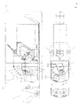
- a milling machining center does not refer to one here described processing unit 1 with a horizontal Work spindle, one workpiece side 2 and two fixed ones Spaces 3 or - optionally - two rotatable ones Clamping locations 4 for mutual exchange of workpieces on.
- the workpiece side 2 consists of an NC rotary table 5, which picks up a pallet 6. On the latter is a Workpiece 7 - in the drawing it is at its maximum possible size shown - attached.
- the NC rotary table 5 is around a through the center of the workpiece 7 NC axis of rotation 8 around a basically infinitely large Angle of rotation 9 rotatable.
- the NC rotary table 5 is on a swivel arm 10 a swivel body 11 arranged, which in turn by a NC swivel axis 12 is rotatable.
- the arrangement of the pivot body 11 is such that in the vertical machining position of the on the Swivel arm 10 located NC rotary table 5, the NC swivel axis 12 runs orthogonal to the NC axis of rotation 8 and this cuts approximately in the middle of the workpiece 7.
- the by the rotation about the NC pivot axis 12 of the Swivel body 11 realized swivel range 13 can Embodiment shown here up to an angle range from 180 °.
- the NC rotary table 5 arranged on the swivel body 11 receiving swivel arm 10 is about a horizontal axis 14, by the end of the Swivel arm 10 located pivot point 14a, pivoted.
- This axis 14 again runs orthogonal to both the NC axis of rotation 8 and the NC swivel axis 12 and includes one of the swing arm 10th realized swivel range of about 90 °.
- This entire workpiece side 2 is one surrounding workspace cover 15 that can be pushed on.
- rotatable Tension slots 4 are used that are opposite the fixed ones 3 have the advantage that the operator of all sides have free access.
- At the rotatable parking lot 4 are arranged according to mounting pin 17.
- the rotatable span support 18 has one by Center of the workpiece 7 coaxial to the NC swivel axis 12 extending axis of rotation 19.
- first and a second instep 20 and 21 each have a pallet 22 and a pallet 23 stored.
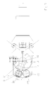
- 5 is a variant with five clamping positions 20, 21, 24, 25, 26 shown. Both fixed and rotatable clamping positions are also used.
- the central axes of the clamping positions 20, 21, 24, 25, 26 are located on a fictitious arc, the Radius the distance of the NC axis of rotation 8 from the NC swivel axis 12 in a horizontal position on the Swivel arm 10 located NC rotary table 8 corresponds.
- the mode of action is as follows:
- the pallet 6 can now on the mounting pin 16 of the first Spannplatzes 20 are filed.
- the swivel body 11 becomes about the NC swivel axis 12 twisted into the target position of the second clamping position 21 (Fig. 3).
- the pallet 23 is then at the second clamping position 21 clamped by the NC rotary table 5.
- NC axes - NC axis of rotation 8 and NC swivel axis 12 - are again orthogonal to each other and cut approximately in the center of the workpiece 7. This course losses that would otherwise occur in the vertical direction (y-axis) and occur in the direction of the work spindle (z-axis) would be avoided. This has the advantage that the Dimensions of the processing units of the Milling center can be smaller.
- the Invention the possibility of even more areas of the Workpiece 7 within this one setting, in which the NC rotary table 5 in the vertical position located to edit. Because of the rotation about the NC swivel axis 12 of the swivel body 11 realized swivel range 13 is the NC rotary table 5 in a position opposite the tool bringable, the processing of e.g. sloping surfaces and holes also from the direction of the pallet clamping surface allows.
Landscapes
- Engineering & Computer Science (AREA)
- Mechanical Engineering (AREA)
- Feeding Of Workpieces (AREA)
- Machine Tool Units (AREA)
- Shovels (AREA)
- Milling Processes (AREA)
Abstract
Description
In der horizontalen Position des NC-Drehtisches verlaufen die NC-Drehachse und die NC-Schwenkachse parallel zueinander.
Außerdem ist durch den bei der Drehung um die NC-Schwenkachse des Schwenkkörpers verwirklichten Schwenkbereich der NC-Drehtisch in eine Position gegenüber der das Werkzeug tragenden Bearbeitungseinheit bringbar, die eine Bearbeitung von mehr als fünf Seiten des Werkstücks ermöglicht.
Claims (11)
- Werkzeugmaschine, insbesondere Fräsbearbeitungszentrum, mit einer einen Werkzeugträger aufnehmenden Bearbeitungseinheit (1) mit vorzugsweise waagerechter Arbeitsspindel, mit einem um eine NC-Drehachse (8) drehbaren und um eine NC-Schwenkachse (12) schwenkbaren NC-Drehtisch (5) zur Aufnahme einer Palette (6) und/oder eines Werkstücks (7) für die Mehrseitenbearbeitung, mit mindestens zwei Spannplätzen (20,21) zum wechselseitigen Tausch der Werkstücke, dadurch gekennzeichnet, daß der NC-Drehtisch (5) um eine dritte, sowohl zur NC-Drehachse (8) als auch zur NC-Schwenkachse (12) orthogonal verlaufende, Achse (14) schwenkbar ist.
- Werkzeugmaschine nach Anspruch 1, dadurch gekennzeichnet, daß der NC-Drehtisch (5) durch eine Schwenkbewegung um die dritte Achse (14) aus einer vertikalen in eine horizontale Position und umgekehrt bringbar ist.
- Werkzeugmaschine nach Anspruch 1 oder 2, dadurch gekennzeichnet, daß in der vertikalen Position des NC-Drehtisches (5) die NC-Drehachse (8) und die NC-Schwenkachse (12) orthogonal zueinander verlaufen und sich annähernd im Mittelpunkt des sich auf dem NC-Drehtisch (5) befindenden Werkstückes (7) schneiden.
- Werkzeugmaschine nach einem der Ansprüche 1 bis 3, dadurch gekennzeichnet, daß in der horizontalen Position des NC-Drehtisches (5) die NC-Drehachse (8) und die NC-Schwenkachse (12) parallel zueinander verlaufen.
- Werkzeugmaschine nach einem der Ansprüche 1 bis 4, dadurch gekennzeichnet, daß der NC-Drehtisch (5) auf einem Schwenkarm (10) eines um die senkrechte NC-Schwenkachse (12) drehbaren Schwenkkörpers (11) angeordnet ist, wobei der Schwenkarm (10) zudem um die waagerechte, durch einen an seinem werkstückabgewandten, schwenkkörpernahen Ende befindlichen Drehpunkt (14a) führende Achse (14) schwenkbar ist.
- Werkzeugmaschine nach einem der Ansprüche 1 bis 5, dadurch gekennzeichnet, daß der NC-Drehtisch (5) durch den um die dritte Achse (14) bewegbaren Schwenkarm (10) aus einer vertikalen Bearbeitungsposition in eine horizontale Palettenwechselposition außerhalb des Arbeitsraumes und umgekehrt schwenkbar ist.
- Werkzeugmaschine nach einem der Ansprüche 1 bis 6, dadurch gekennzeichnet, daß die auf dem NC-Drehtisch (5) befestigte und mit diesem aus dem Arbeitsraum herausschwenkbare Palette (6) mit einem außerhalb des Arbeitsraumes befindlichen Spannplatz (20,21) in und außer Eingriff bringbar ist.
- Werkzeugmaschine nach einem der Ansprüche 1 bis 7, dadurch gekennzeichnet, daß innerhalb des Schwenkbereiches (13) des um die NC-Schwenkachse (12) drehbaren Schwenkkörpers (11) mehr als zwei Spannplätze (20, 21, 24, 25, 26) für Paletten (6, 22, 23) und/oder Werkstücke (7) vorgesehen sind.
- Werkzeugmaschine nach Anspruch 8, dadurch gekennzeichnet, daß die Mittelachsen der Spannplätze (20, 21, 24, 25, 26) auf einem fiktiven Kreisbogen angeordnet sind, dessen Radius dem Abstand der NC-Drehachse (8) des sich in der horizontalen Lage befindenden, auf dem Schwenkarm (10) befestigten NC-Drehtisches (5) von der NC-Schwenkachse (12) entspricht.
- Werkzeugmaschine nach einem der Ansprüche 1 bis 9, dadurch gekennzeichnet, daß durch den bei der Drehung um die NC-Schwenkachse (12) des Schwenkkörpers (11) verwirklichten Schwenkbereich (13) der NC-Drehtisch (5) in eine Position gegenüber der das Werkzeug tragenden Bearbeitungseinheit (1) bringbar ist, die eine Bearbeitung von mehr als fünf Seiten ermöglicht.
- Werkzeugmaschine nach einem der Ansprüche 1 bis 10, dadurch gekennzeichnet, daß während der gesamten Mehrseitenbearbeitung des auf der Palette (6) des NC-Drehtisches (5) aufgespannten Werkstücks (7) der NC-Drehtisch (5) vom Schwenkarm (10) des Schwenkkörpers (11) in einer vertikalen Position gehalten wird.
Applications Claiming Priority (2)
| Application Number | Priority Date | Filing Date | Title |
|---|---|---|---|
| DE10064416 | 2000-12-21 | ||
| DE10064416A DE10064416C2 (de) | 2000-12-21 | 2000-12-21 | Werkzeugmaschine, insbesondere Fräsbearbeitungszentrum |
Publications (2)
| Publication Number | Publication Date |
|---|---|
| EP1216773A1 true EP1216773A1 (de) | 2002-06-26 |
| EP1216773B1 EP1216773B1 (de) | 2003-03-19 |
Family
ID=7668547
Family Applications (1)
| Application Number | Title | Priority Date | Filing Date |
|---|---|---|---|
| EP01129950A Expired - Lifetime EP1216773B1 (de) | 2000-12-21 | 2001-12-17 | Werkzeugmaschine, insbesondere Fräsbearbeitungszentrum |
Country Status (3)
| Country | Link |
|---|---|
| EP (1) | EP1216773B1 (de) |
| AT (1) | ATE234700T1 (de) |
| DE (2) | DE10064416C2 (de) |
Cited By (2)
| Publication number | Priority date | Publication date | Assignee | Title |
|---|---|---|---|---|
| WO2006133583A1 (de) * | 2005-06-13 | 2006-12-21 | Ruefli Franz | Vorrichtung zur bearbeitung aller seiten eines werkstücks mit zwei parallelkinematischen trägerebenen |
| GB2445190A (en) * | 2006-12-30 | 2008-07-02 | Joshua Nicholas George Reid | Subtractive Prototyping Machine |
Families Citing this family (3)
| Publication number | Priority date | Publication date | Assignee | Title |
|---|---|---|---|---|
| DE102007034104A1 (de) | 2007-07-21 | 2009-01-22 | Schiess Gmbh | NC-Dreh-, Verschiebe- und Schwenktisch für ein Horizontalbearbeitungszentrum |
| DE102008031487A1 (de) * | 2008-07-03 | 2010-01-07 | Ex-Cell-O Gmbh | Bearbeitungsanlage für Werkstücke |
| DE102010048435A1 (de) * | 2010-10-15 | 2012-04-19 | Franz Ehrenleitner | Werkzeugmaschine, insbesondere Fräsmaschine |
Citations (1)
| Publication number | Priority date | Publication date | Assignee | Title |
|---|---|---|---|---|
| DE2833145A1 (de) * | 1978-07-28 | 1980-02-07 | Ewertowski Ing Buero | Waagerecht-bohr-fraesmaschine |
Family Cites Families (3)
| Publication number | Priority date | Publication date | Assignee | Title |
|---|---|---|---|---|
| DE8809972U1 (de) * | 1988-08-04 | 1988-10-13 | Frank, Harry, 5902 Netphen | Vorrichtung zur Positionierung eines Werkstücks |
| DE4027895A1 (de) * | 1990-09-03 | 1992-03-05 | Wanderer Maschinen Gmbh | Werkzeugmaschine |
| DE19856863C2 (de) * | 1998-12-09 | 2003-07-17 | Alzmetall Werkzeugmasch | Werkzeugmaschine |
-
2000
- 2000-12-21 DE DE10064416A patent/DE10064416C2/de not_active Expired - Fee Related
-
2001
- 2001-12-17 EP EP01129950A patent/EP1216773B1/de not_active Expired - Lifetime
- 2001-12-17 DE DE50100122T patent/DE50100122D1/de not_active Expired - Fee Related
- 2001-12-17 AT AT01129950T patent/ATE234700T1/de not_active IP Right Cessation
Patent Citations (1)
| Publication number | Priority date | Publication date | Assignee | Title |
|---|---|---|---|---|
| DE2833145A1 (de) * | 1978-07-28 | 1980-02-07 | Ewertowski Ing Buero | Waagerecht-bohr-fraesmaschine |
Cited By (2)
| Publication number | Priority date | Publication date | Assignee | Title |
|---|---|---|---|---|
| WO2006133583A1 (de) * | 2005-06-13 | 2006-12-21 | Ruefli Franz | Vorrichtung zur bearbeitung aller seiten eines werkstücks mit zwei parallelkinematischen trägerebenen |
| GB2445190A (en) * | 2006-12-30 | 2008-07-02 | Joshua Nicholas George Reid | Subtractive Prototyping Machine |
Also Published As
| Publication number | Publication date |
|---|---|
| DE50100122D1 (de) | 2003-04-24 |
| EP1216773B1 (de) | 2003-03-19 |
| ATE234700T1 (de) | 2003-04-15 |
| DE10064416A1 (de) | 2002-07-04 |
| DE10064416C2 (de) | 2003-11-27 |
Similar Documents
| Publication | Publication Date | Title |
|---|---|---|
| DE69107700T2 (de) | Werkzeugmaschine. | |
| DE3729162C2 (de) | ||
| EP1291122B1 (de) | Fräs- und Bohrbearbeitungszentrum | |
| DE69602079T2 (de) | Werkzeugmaschine mit horizontalen spindeln | |
| EP0721819B1 (de) | Werkzeugmaschine | |
| DE3427245C2 (de) | Werkzeugmaschine | |
| EP0995539B1 (de) | Bearbeitungsvorrichtung für Werkstücke | |
| EP1188511A2 (de) | Werkzeugmaschine mit einem motorisch fahrbaren Werkzeugschlitten | |
| EP1765550A1 (de) | Werkzeugmaschine und verfahren zum werkzeugwechsel an einer werkzeugmaschine | |
| DE102012201728B4 (de) | Werkzeugmaschine mit palettenwechselvorrichtung | |
| DE19854276C2 (de) | Werkzeugmaschinen-Anordnung mit einer Vorrichtung für einen automatischen Werkzeugwechsel | |
| EP0908269A2 (de) | Werkzeugmaschinengruppe mit zwei einander gegenüberstehenden Bearbeitungseinheiten | |
| EP1575737B1 (de) | Werkzeugmaschine mit palettenwechselmodul | |
| EP1413395A1 (de) | Werkzeugmaschine | |
| DE3420719A1 (de) | Werkzeugmaschine mit zwei werkstueckspindeln | |
| DE19934598B4 (de) | Universal-Fräs- und Bohrmaschine | |
| EP1216773B1 (de) | Werkzeugmaschine, insbesondere Fräsbearbeitungszentrum | |
| EP0331178B1 (de) | Kompaktaufbau einer Säulenbohrmaschine | |
| DE102019211981A1 (de) | Werkzeugwechselvorrichtung zum einsatz an einer werkzeugmaschine und werkzeugmaschine mit einer derartigen werkzeugwechselvorrichtung | |
| EP0949029B1 (de) | Maschine zur Bearbeitung von stangenförmigen Werkstücken | |
| DE4405507A1 (de) | CNC-gesteuertes Bearbeitungszentrum | |
| EP1509360B1 (de) | Vorrichtung zur bearbeitung von werkstücken sowie maschinenanordnung hierzu | |
| DE29821047U1 (de) | Werkzeugmaschinen-Anordnung mit einer Vorrichtung für einen automatischen Werkzeugwechsel | |
| DE3824572C2 (de) | ||
| DE20115005U1 (de) | Fräs- und Bohrbearbeitungszentrum |
Legal Events
| Date | Code | Title | Description |
|---|---|---|---|
| PUAI | Public reference made under article 153(3) epc to a published international application that has entered the european phase |
Free format text: ORIGINAL CODE: 0009012 |
|
| 17P | Request for examination filed |
Effective date: 20011219 |
|
| AK | Designated contracting states |
Kind code of ref document: A1 Designated state(s): AT BE CH CY DE DK ES FI FR GB GR IE IT LI LU MC NL PT SE TR |
|
| AX | Request for extension of the european patent |
Free format text: AL;LT;LV;MK;RO;SI |
|
| GRAH | Despatch of communication of intention to grant a patent |
Free format text: ORIGINAL CODE: EPIDOS IGRA |
|
| GRAH | Despatch of communication of intention to grant a patent |
Free format text: ORIGINAL CODE: EPIDOS IGRA |
|
| GRAH | Despatch of communication of intention to grant a patent |
Free format text: ORIGINAL CODE: EPIDOS IGRA |
|
| GRAA | (expected) grant |
Free format text: ORIGINAL CODE: 0009210 |
|
| AK | Designated contracting states |
Designated state(s): AT BE CH CY DE DK ES FI FR GB GR IE IT LI LU MC NL PT SE TR |
|
| AKX | Designation fees paid |
Designated state(s): AT BE CH CY DE DK ES FI FR GB GR IE IT LI LU MC NL PT SE TR |
|
| PG25 | Lapsed in a contracting state [announced via postgrant information from national office to epo] |
Ref country code: GR Free format text: LAPSE BECAUSE OF FAILURE TO SUBMIT A TRANSLATION OF THE DESCRIPTION OR TO PAY THE FEE WITHIN THE PRESCRIBED TIME-LIMIT Effective date: 20030319 Ref country code: GB Free format text: LAPSE BECAUSE OF FAILURE TO SUBMIT A TRANSLATION OF THE DESCRIPTION OR TO PAY THE FEE WITHIN THE PRESCRIBED TIME-LIMIT Effective date: 20030319 Ref country code: FI Free format text: LAPSE BECAUSE OF FAILURE TO SUBMIT A TRANSLATION OF THE DESCRIPTION OR TO PAY THE FEE WITHIN THE PRESCRIBED TIME-LIMIT Effective date: 20030319 Ref country code: IE Free format text: LAPSE BECAUSE OF FAILURE TO SUBMIT A TRANSLATION OF THE DESCRIPTION OR TO PAY THE FEE WITHIN THE PRESCRIBED TIME-LIMIT Effective date: 20030319 Ref country code: FR Free format text: LAPSE BECAUSE OF FAILURE TO SUBMIT A TRANSLATION OF THE DESCRIPTION OR TO PAY THE FEE WITHIN THE PRESCRIBED TIME-LIMIT Effective date: 20030319 Ref country code: TR Free format text: LAPSE BECAUSE OF FAILURE TO SUBMIT A TRANSLATION OF THE DESCRIPTION OR TO PAY THE FEE WITHIN THE PRESCRIBED TIME-LIMIT Effective date: 20030319 Ref country code: NL Free format text: LAPSE BECAUSE OF FAILURE TO SUBMIT A TRANSLATION OF THE DESCRIPTION OR TO PAY THE FEE WITHIN THE PRESCRIBED TIME-LIMIT Effective date: 20030319 |
|
| REG | Reference to a national code |
Ref country code: GB Ref legal event code: FG4D Free format text: NOT ENGLISH |
|
| REG | Reference to a national code |
Ref country code: CH Ref legal event code: EP |
|
| REG | Reference to a national code |
Ref country code: IE Ref legal event code: FG4D Free format text: GERMAN |
|
| REF | Corresponds to: |
Ref document number: 50100122 Country of ref document: DE Date of ref document: 20030424 Kind code of ref document: P |
|
| PG25 | Lapsed in a contracting state [announced via postgrant information from national office to epo] |
Ref country code: SE Free format text: LAPSE BECAUSE OF FAILURE TO SUBMIT A TRANSLATION OF THE DESCRIPTION OR TO PAY THE FEE WITHIN THE PRESCRIBED TIME-LIMIT Effective date: 20030619 Ref country code: DK Free format text: LAPSE BECAUSE OF FAILURE TO SUBMIT A TRANSLATION OF THE DESCRIPTION OR TO PAY THE FEE WITHIN THE PRESCRIBED TIME-LIMIT Effective date: 20030619 |
|
| PG25 | Lapsed in a contracting state [announced via postgrant information from national office to epo] |
Ref country code: PT Free format text: LAPSE BECAUSE OF FAILURE TO SUBMIT A TRANSLATION OF THE DESCRIPTION OR TO PAY THE FEE WITHIN THE PRESCRIBED TIME-LIMIT Effective date: 20030620 |
|
| NLV1 | Nl: lapsed or annulled due to failure to fulfill the requirements of art. 29p and 29m of the patents act | ||
| GBV | Gb: ep patent (uk) treated as always having been void in accordance with gb section 77(7)/1977 [no translation filed] |
Effective date: 20030319 |
|
| PG25 | Lapsed in a contracting state [announced via postgrant information from national office to epo] |
Ref country code: ES Free format text: LAPSE BECAUSE OF FAILURE TO SUBMIT A TRANSLATION OF THE DESCRIPTION OR TO PAY THE FEE WITHIN THE PRESCRIBED TIME-LIMIT Effective date: 20030930 |
|
| REG | Reference to a national code |
Ref country code: IE Ref legal event code: FD4D Ref document number: 1216773E Country of ref document: IE |
|
| PG25 | Lapsed in a contracting state [announced via postgrant information from national office to epo] |
Ref country code: CY Free format text: LAPSE BECAUSE OF FAILURE TO SUBMIT A TRANSLATION OF THE DESCRIPTION OR TO PAY THE FEE WITHIN THE PRESCRIBED TIME-LIMIT Effective date: 20031217 Ref country code: AT Free format text: LAPSE BECAUSE OF NON-PAYMENT OF DUE FEES Effective date: 20031217 Ref country code: LU Free format text: LAPSE BECAUSE OF NON-PAYMENT OF DUE FEES Effective date: 20031217 |
|
| PG25 | Lapsed in a contracting state [announced via postgrant information from national office to epo] |
Ref country code: MC Free format text: LAPSE BECAUSE OF NON-PAYMENT OF DUE FEES Effective date: 20031231 Ref country code: BE Free format text: LAPSE BECAUSE OF NON-PAYMENT OF DUE FEES Effective date: 20031231 |
|
| PLBE | No opposition filed within time limit |
Free format text: ORIGINAL CODE: 0009261 |
|
| STAA | Information on the status of an ep patent application or granted ep patent |
Free format text: STATUS: NO OPPOSITION FILED WITHIN TIME LIMIT |
|
| EN | Fr: translation not filed | ||
| 26N | No opposition filed |
Effective date: 20031222 |
|
| BERE | Be: lapsed |
Owner name: *STARRAGHECKERT G.M.B.H. Effective date: 20031231 |
|
| PG25 | Lapsed in a contracting state [announced via postgrant information from national office to epo] |
Ref country code: IT Free format text: LAPSE BECAUSE OF NON-PAYMENT OF DUE FEES Effective date: 20051217 |
|
| PG25 | Lapsed in a contracting state [announced via postgrant information from national office to epo] |
Ref country code: LI Free format text: LAPSE BECAUSE OF NON-PAYMENT OF DUE FEES Effective date: 20051231 Ref country code: CH Free format text: LAPSE BECAUSE OF NON-PAYMENT OF DUE FEES Effective date: 20051231 |
|
| REG | Reference to a national code |
Ref country code: CH Ref legal event code: PL |
|
| PGFP | Annual fee paid to national office [announced via postgrant information from national office to epo] |
Ref country code: DE Payment date: 20071029 Year of fee payment: 7 |
|
| PG25 | Lapsed in a contracting state [announced via postgrant information from national office to epo] |
Ref country code: DE Free format text: LAPSE BECAUSE OF NON-PAYMENT OF DUE FEES Effective date: 20090701 |
|
| PGFP | Annual fee paid to national office [announced via postgrant information from national office to epo] |
Ref country code: IT Payment date: 20071222 Year of fee payment: 7 |
|
| PGRI | Patent reinstated in contracting state [announced from national office to epo] |
Ref country code: IT Effective date: 20091201 |
|
| PGRI | Patent reinstated in contracting state [announced from national office to epo] |
Ref country code: IT Effective date: 20091201 |