EP1216545B1 - Procede et appareil relatifs a un protocole multiple de telecommunications sans fil incluant une reduction proactive des interferences - Google Patents
Procede et appareil relatifs a un protocole multiple de telecommunications sans fil incluant une reduction proactive des interferences Download PDFInfo
- Publication number
- EP1216545B1 EP1216545B1 EP00967091A EP00967091A EP1216545B1 EP 1216545 B1 EP1216545 B1 EP 1216545B1 EP 00967091 A EP00967091 A EP 00967091A EP 00967091 A EP00967091 A EP 00967091A EP 1216545 B1 EP1216545 B1 EP 1216545B1
- Authority
- EP
- European Patent Office
- Prior art keywords
- devices
- protocol
- transmission time
- wireless
- accordance
- Prior art date
- Legal status (The legal status is an assumption and is not a legal conclusion. Google has not performed a legal analysis and makes no representation as to the accuracy of the status listed.)
- Expired - Lifetime
Links
Images


Classifications
-
- H—ELECTRICITY
- H04—ELECTRIC COMMUNICATION TECHNIQUE
- H04W—WIRELESS COMMUNICATION NETWORKS
- H04W88/00—Devices specially adapted for wireless communication networks, e.g. terminals, base stations or access point devices
- H04W88/02—Terminal devices
- H04W88/06—Terminal devices adapted for operation in multiple networks or having at least two operational modes, e.g. multi-mode terminals
-
- H—ELECTRICITY
- H04—ELECTRIC COMMUNICATION TECHNIQUE
- H04B—TRANSMISSION
- H04B1/00—Details of transmission systems, not covered by a single one of groups H04B3/00 - H04B13/00; Details of transmission systems not characterised by the medium used for transmission
- H04B1/69—Spread spectrum techniques
- H04B1/713—Spread spectrum techniques using frequency hopping
- H04B1/7156—Arrangements for sequence synchronisation
-
- H—ELECTRICITY
- H04—ELECTRIC COMMUNICATION TECHNIQUE
- H04L—TRANSMISSION OF DIGITAL INFORMATION, e.g. TELEGRAPHIC COMMUNICATION
- H04L69/00—Network arrangements, protocols or services independent of the application payload and not provided for in the other groups of this subclass
- H04L69/18—Multiprotocol handlers, e.g. single devices capable of handling multiple protocols
-
- H—ELECTRICITY
- H04—ELECTRIC COMMUNICATION TECHNIQUE
- H04W—WIRELESS COMMUNICATION NETWORKS
- H04W16/00—Network planning, e.g. coverage or traffic planning tools; Network deployment, e.g. resource partitioning or cells structures
- H04W16/14—Spectrum sharing arrangements between different networks
Definitions
- the present invention relates to the field of wireless communication. More specifically, the present invention relates to the problem of concurrent wireless communication with multiple communication partners of different wireless communication protocols.
- wireless communication Once confined to the privileged, wireless voice communication have become affordable and available to the masses.
- Bluetooth technology A leading candidate to accomplish the former is commonly known to those skilled in the art as the Bluetooth technology or Bluetooth protocol.
- Examples of technology to accomplish the later include the different variants of the IEEE 802.11 Standard published by the Institute of Electrical and Electronic Engineers, 802.11 (Frequency Hoping, Direct Sequence), 802.11a, 802.1b, as well as Home RF, also known as Shared Wireless Access Protocol (SWAP) to those skilled in the art.
- SWAP Shared Wireless Access Protocol
- One such applications is having a notebook computer being able to communicate with peripheral devices such as a phone, a printer, a scanner and the like, in accordance with the Bluetooth protocol; and with other computing devices, such as other peer computers or servers, communication devices, such as modems or adapters, and networking devices, such as gateways, routers, switches and the like, in accordance with one of the 802.11 protocols or Home RF.
- the need cannot be met by simply providing the device with multiple transmitters, one for each protocol. The reason is because if multiple ones of these transmitters were to transmit at the same time. The transmitters are going to interfere with each other, resulting in corruption and/or loss of data, as well as degradation in performance.
- the present invention substantially address this need in a very efficient and low cost manner. This and Other advantages of the present invention will be readily apparent from the description to follow.
- WO 99/29126 discloses a terminal which can operate simultaneously in a first and second radio communications network.
- the terminal includes a first transceiver which transmits and receives in the first radio communications network and a second transceiver which transmits and receives in the second radio communication network.
- the terminal synchronizes transmissions from the transceivers to prevent signal collision.
- a collection of networked apparatuses comprising: a first plurality of apparatuses including first and second subsets wirelessly networked together, with each apparatus being equipped to communicate wirelessly in accordance with a first frequency hopping protocol, with the first and second subsets operating in accordance with a first and a second frequency hopping pattern based on a first and a second pseudo random pattern; a second plurality of apparatuses wirelessly networked together, with each apparatus being equipped to communicate wirelessly in accordance with a second protocol; and a multi-protocol apparatus equipped with a first and a second transceiver to communicate wirelessly with the first and second plurality of apparatuses in accordance with the first and second protocols respectively, wherein the first and second subsets of the first plurality of apparatus are operationally synchronized to a reference signal, and the second plurality of apparatuses are operationally aligned to the same reference signal, and the multi-protocol apparatus includes control logic to operate in a manner that is
- the invention provides an apparatus comprising: a plurality of wireless transceivers to transmit and receive signals in accordance with a first and a second protocol, to and from first and second network devices of a first and second wireless network communicatively coupled to the apparatus, the first network devises comprising first and second subsets that transmit and receive in accordance with a first and second frequency hopping pattern based on a first and a second pseudo random pattern in a synchronized manner, the first protocol being a frequency hopping protocol; and at least one controller manager coupled to the wireless transceivers to control and coordinate operation of the wireless transceivers in a manner that complements the synchronized operation of the first and second subsets of the first network devices to reduce interference among the apparatus and the first and second network devices, wherein the at least one controller manager includes logic to align transmit and receive operations of said wireless transceivers to a reference signal against which the first and second subsets of the first network devices synchronize operations, the alignment to the reference signal being effectuated incrementally in a
- a further aspect provides a method of operating the apparatus of the above-mentioned aspect.
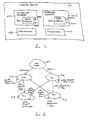
- wireless device 100 is provided with wireless transceivers 102a and 102b to transmit and receive signals wirelessly in accordance with a first and a second wireless communication protocol, to enable device 100 to be communicatively coupled to devices 104a and devices 104b of wireless networks 108a and 108b respectively.
- Wireless device 100 further includes controller managers 106a and 106b to control the operation of wireless transceivers 102a and 102b respectively.
- controller managers 106a and 106b control transmits and receives by wireless transceivers 102a and 102b, in a coordinated manner, in accordance with the present invention, to allow wireless device 100 to operate with devices 104a and devices 104b of wireless network 108a and 108b in accordance with the respective wireless communication protocols at the same time.
- controller managers 106a and 106b control transmits and receives by wireless transceivers 102a and 102b (hereinafter, simply transceivers), in a coordinated manner. More specifically, in this embodiment, controller managers 106a and 106b control transceivers 102a and 102b to alternate between transmits by one of the two transceivers and receives by both of the two transceivers.
- Figure 2 illustrates a period of operation in accordance with this embodiment.
- control manager 106a controls transceiver 102a to perform transmit of signals to devices 104a of wireless network 108a (hereinafter, simply network) in accordance with the first wireless communication protocol (hereinafter, simply protocol), while control manager 106b controls transceiver 102b to neither perform transmit nor receive of signals to and from devices 104b of network 108b.
- simply protocol the first wireless communication protocol
- control manager 106b controls transceiver 102b to neither perform transmit nor receive of signals to and from devices 104b of network 108b.
- time period T3 for duration t3, the reverse is performed.
- Control manager 106b controls transceiver 102b to perform transmit of signals to devices 104b of network 108b in accordance with the second protocol
- control manager 106a controls transceiver 102a to neither perform transmit nor receive of signals to and from devices 104a of network 108a.
- control managers 106a and 106b control both transceivers 102a and 102b to perform receive of signals from devices 104a and 104b of network 108a and 108b in accordance with the respective protocols respectively.
- devices 104a are able to receive in time period T1, and transmit when there are packets to transmit, but otherwise receive, in time periods T2-T4.
- devices 104b are able to receive in time period T3, and transmit when there are packets to transmit, but otherwise receive, in time periods T1-T2 and T4.
- wireless device 100 is able to operate with devices 104a and 104b of networks 108a and 108b in two wireless protocols at the same time.
- time periods T1-T4 may or may not be equal in duration. That is, numerically t1-t4 may or may not be equal.
- duration t1-t4 of time periods T1-T4 are dynamically and adaptively set.
- duration t1-t4 of time periods T1-T4 are adaptively set based at least in part of transmit and receive workloads of networks 108a and 108b.
- transceivers 102a and 102b as well as controller managers 106a and 106b are otherwise intended to represent a broad range of these elements known in the art. Accordingly, except for the teachings of the present invention, which will be further described below, transceivers 102a and 102b and controller managers 106a and 106b will not be otherwise further described.
- Wireless device 100 is intended to represent a wide range of devices that can benefit from having the ability to wirelessly operate with other wireless devices in two or more wireless communication protocols at the same time.
- Examples of device 100 include but not limited to computers of various form factors, such as desktop, notebook, palm size and so forth, controller devices (i.e. master devices) to manage and control the operation of networks 108a and 108b, and gateway devices to facilitate communication between devices 104a and devices 104b.
- devices 104a and 104b are intended to represent a broad range of devices that can benefit from being able to communicate wirelessly.
- devices 104a include but not limited to phones, video cameras, speakers, modems, printers and scanners equipped to wireless communicate in accordance with the Bluetooth protocol.
- devices 104b include clients and servers, as well as gateways, modems, hubs, routers, and switches equipped to wireless communicate in accordance with a selected variant of the IEEE 802.11 protocols or Home RF.
- Fig. 1 For ease of understanding, only two groups of devices 104a and 104b, communicating in accordance with the first and second wireless communication protocols are shown in Fig. 1 . However, from the description to follow, it will be readily apparent to those skilled in the art, the present invention may be practiced with more than two transceivers (as long as the transceivers are likewise coordinated).
- each controller manager 106a/106b of wireless device 100 is endowed with a state machine 300a/300b to complementarily assist the controller manager 106a/106b to control its transceiver 102a/102b in the above described coordinated manner.
- each state machine 300a/300b in addition to idle state 410, has four operating states 412-418 (TX, RX1, NOP, and RX2) to output a signal 304a/304b denoting a selected one of a transmit (TX) operation, a receive (RX) operation and no-op (NOP) for its controller manager 106a/106b.
- TX transmit
- RX receive
- NOP no-op
- each state machine 300a/300b Upon power-on or reset, each state machine 300a/300b either transitions from idle state 410 to TX state 412 or NOP state 416, depending on the state of configuration (config) signal 302a/302b.
- One state machine, e.g. 300a is configured to transition from idle state 410 to TX state 412, while the other state machine, e.g. 300b, is configured to transition from idle state 410 to TX state 412.
- Config signal 302a/302b may be set e.g. via a jumper or other equivalent means, as well as through software.
- state machine 300a/300b While in TX state 412, state machine 300a/300b remains in the state for duration ts1, outputting signal 304a/304b denoting TX operation for its controller manager 1026a/106b.
- t1 and t3 may take on different values
- one state machine, e.g. 300a is configured with ts1 set to t1
- the other state machine, e.g. 300b is configured with ts1 set to t3.
- Ts1 may be selectively set in any one of a number of techniques known in the art, e.g. through separate registers or multiplexing circuitry.
- state machine 300a/300b transitions from TX state 412 to RX1 state 414.
- state machine 300a/300b While in RX1 state 414, state machine 300a/300b remains in the state for duration ts2, outputting signal 304a/304b denoting RX operation for its controller manager 106a/106b.
- t2 and t4 may take on different values
- one state machine, e.g. 300a is configured with ts2 set to t2
- the other state machine, e.g. 300b is configured with ts2 set to t4.
- Ts2 may likewise be selectively set in any one of a number of techniques known in the art.
- state machine 300a/300b While in NOP state 416, state machine 300a/300b remains in the state for duration ts3, outputting signal 304a/304b denoting NOP for its controller manager 106a/106b.
- t1 and t3 may take on different values
- one state machine, e.g. 300a is configured with ts3 set to t3
- the other state machine, e.g. 300b is configured with ts3 set to t1.
- Ts3 may likewise be selectively set in anyone of a number of techniques known in the art.
- state machine 300a/300b While in RX2 state 418, state machine 300a/300b remains in the state for duration ts4, outputting signal 304a/304b denoting RX operation for its controller manager 106a/106b.
- t2 and t4 may take on different values
- one state machine, e.g. 300a is configured with ts4 set to t4
- the other state machine, e.g. 300b is configured with ts4 set to t2.
- Ts4 may likewise be selectively set in any one of a number of techniques known in the art.
- state machine 300a/300b continues operation as described earlier.
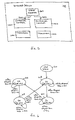
- FIG. 5 and 6 wherein a block diagram and a state diagram illustrating wireless device 100 of Fig. 1 in further detail, in accordance with another embodiment, are shown.
- each controller manager 106a/106b of wireless device 100 instead of having each controller manager 106a/106b of wireless device 100 be endowed with a state machine to complementarily assist the controller manager 106a/106b to control its transceiver 102a/102b in the above described coordinated manner, wireless device 100 is endowed with a single state machine 500 to assist both controller managers 106a and 106b.
- state machine 500 in addition to idle state 610, has four operating states 612-618 (S1 - S4) to output a pair of signals 504a-504b denoting a selected combination of operations, TX with NOP, both RX, and NOP with TX for controller managers 106a and 106b.
- state machine 500 Upon power-on or reset, state machine 500 transitions from idle state 610 to S1 state 612. While in S1 state 612, state machine 500 remains in the state for duration ts1, outputting signal 504a-504b denoting TX and NOP for controller managers 106a and 106b. Ts1 is set to t1. Upon expiration of ts1, state machine 500 transitions from S1 state 612 to S2 state 614. While in S2 state 614, state machine 500 remains in the state for duration ts2, outputting signal 504a-504b denoting RX for both controller managers 106a and 106b. Ts2 is set to t2. Upon expiration of ts2, state machine 500 transitions from S2 state 614 to S3 state 616.
- state machine 500 While in S3 state 616, state machine 500 remains in the state for duration ts3, outputting signal 504a-504b denoting NOP and TX for controller managers 106a and 106b. Ts3 is set to t3. Upon expiration of ts3, state machine 500 transitions from S3 state 616 to S4 state 618. While in S4 state 618, state machine 500 remains in the state for duration ts4, outputting signal 504a-504b denoting RX for both controller managers 106a and 106b. Ts4 is set to t4. Upon expiration of ts4, state machine 500 transitions from S4 state 618 to S1 state 612.
- state machine 500 continues operation as described earlier.
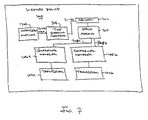
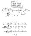
- FIG. 7 a block diagram illustrating wireless device 100 of Fig. 1 in further detail, in accordance with yet another embodiment, is shown.
- wireless device 100 in addition to having wireless device 100 be endowed with a single state machine 700 to assist both controller managers 106a and 106b as described earlier (with signals 708a-708a denoting TX-NOP, RX-RX or NOP-TX), wireless device 100 is further endowed with register 702, time sharing manager 704, and workload monitor 706 operatively coupled to each other and state machine 700 as shown.
- Register 702 stores t1-t4 for state machine 700.
- Time sharing manager 704 dynamically adjusts t1-t4 to enable state machine 700 be able to adaptively assist controller managers 106a and 106b in controlling transceivers 102a and 102b. For the illustrated embodiment, time sharing manager 704 dynamically adjusts t1-t4 based at least in part on transmit and receive workloads of networks 108a and 108b. Transmit and receive workloads are monitored by workload monitor 706 and provided to time sharing manager 704.
- Register 702 may be constituted with any storage circuitry known in the art.
- Time sharing manager 704 and workload monitor 706 may be implemented with any combinatorial logic or in software.
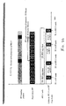
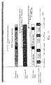
- first protocol of wireless devices 104a of network 108a is assumed to be a frequency hopping protocol as shown, i.e. wireless devices 104a hop from frequency to frequency in accordance with a pseudo random pattern to transmit signals.
- second protocol of wireless devices 104b of network 108b is assumed to be a constant frequency protocol (although in alternate embodiments, it may also be a frequency hopping protocol).
- at least one of the frequencies of the first protocol is the same frequency of the second protocol.
- frequency interference is shown to occur at the 7 th and 14 th hop (f 7 and f 14 ). That is, in accordance with the pseudo random pattern, in each of these two hops, devices 104a transmit in the same frequency employed by devices 104b.
- An example of a frequency hopping protocol is the Bluetooth protocol, and an example of a protocol having an interfering frequency with Bluetooth is the 802.11 protocol.
- the interference pattern is dictated by the intersection of the pseudo random pattern followed by the frequency hopping devices 104a and the frequency employed by devices 104b.
- wireless device 100 coordinates the operation of devices 104a and 104b to proactively reduce actual occurrence of interference. More specifically, for the illustrated embodiments, either devices 104a or devices 104b are selected to be the "dominant" devices. The non-selected devices are considered to be the dominated devices. The dominated devices are notified, from time to time, to suspend operation to pro-actively avoid interference with the dominant devices, allowing the dominant devices to continue to operate without interference. As result, the time consuming collision detection, back off and retries are substantially reduced, and experience has shown that the overall operating efficiencies of both networks improve, the dominated network as well as the dominant network.
- Fig. 8a illustrates a period of operation when devices 104a, the frequency hopping devices, are selected to be the dominant devices
- Fig. 8b illustrates a period of operation when devices 104b are selected to be the dominant devices. That is, under Fig. 8a , devices 104b, upon informed, will temporarily suspend operation to proactively avoid interference, whereas under Fig. 8b , devices 104a, upon informed, will temporarily suspend operation to proactively avoid interference.
- wireless device 100 basically operates as earlier described. Except wireless device 100 assumes the additional responsibilities of determining the pseudo random frequency hopping pattern of devices 104a (in one embodiment, including the interfering frequency), selecting either devices 104a or 104b to be the dominated devices, predicting the occurrence of interference, and preemptively notifying the dominated devices to suspend operation to avoid interference (in one embodiment, conditionally suspending operation).
- wireless device 100 is basically the embodiment earlier described referencing Fig. 7 , except wireless device 100 is further provided with network management application (or network manager) 904 to proactively managing network devices 104a and 104b to reduce actual occurrence of interference.
- Network manager 904 also subsumes the earlier described responsibilities of time sharing manager 704, i.e. monitoring the workloads of the two protocols, and adaptively setting the values of t1-t4 for time period T1-T4.
- network manager 904 monitors the operation of devices 104a and 104b for an observation period, and determines the pseudo random frequency hopping pattern followed by devices 104a (and in one embodiment, the interfering frequency with devices 104b), 912. This may be accomplished using any one of a number of techniques known in the art.
- network manager 904 selects either devices 104a or devices 104b to be the dominant devices, 914.
- network manager 904 makes the selection in accordance with configuration information programmed in configuration register 902. In alternate embodiments, other configuration registers, or other techniques known in the art, such as jumpers, may also be employed to assist network manager 904 in making the selection.
- network manager 904 predicts when interference will occur, using the determined pseudo random pattern and interference frequency, 916. Whenever, an interference is to occur, network manager 904 preemptively notifies the dominated devices to suspend operation accordingly, thereby allowing the dominant devices to operate without interference, 918. [In one embodiment, if the dominated devices are devices 104a, the notification includes the interfering frequency, and the suspension is conditional, only if the predicted frequency is indeed the interfering frequency.] The process continues, as long as there are wireless devices of both types 104a and 104b operating.
- network manager 904 repeats the calibration periodically. In yet another embodiment, network manager 904 monitors actual interference between devices 104a and 104b, and tracks the mean time between interference. Network manager 904 repeats the calibration, whenever the tracked mean time between interference drops below certain given performance level.
- network manager 904 may make the selection of the dominated devices in a dynamic and individualized manner, when an interference is predicted to occur. That is, different device or devices 104a and 104b are dynamically and individually selected for different predictions of interference. Such dynamic, individualized manner of selection may also be made in view of the workloads of the two protocols.
- the above described improved manner of operation may be practiced with minimal or no change to devices 104,a and 104a, as virtually all network devices are capable of temporarily suspending operation responsive to a request.
- the conditional performance may be effectuated through addition of simple frequency testing combinatorial logic.
- wireless device 100 upon selecting the dominated devices at 914, notifies devices 104a and 104b of their respective roles, i.e. whether they are the dominating devices or dominated devices. Further, at least the dominated devices are also provided with a collision map, for the dominated devices to self determine whether interference is to occur. In other words, operation 916 is distributed to the dominated devices, and operation 918 is eliminated.
- the determination of interference further includes prospectively anticipating whether the transmission of a long packet by a dominated device operating in accordance with such frequency hopping protocol will cause interference with the dominating devices.
- a long packet is a packet whose transmission spans multiple ones of the frequency hops. The dominated devices either self-determine or instructed by wireless device 100 (depending on implementations) to refrain from starting such transmission of a long packet unless interference will not occur.
- first protocol of wireless devices 104a of network 108a is assumed to be a frequency hopping protocol
- second protocol of wireless devices 104b of network 108b is assumed to be a constant frequency protocol (although it may also be a frequency hopping protocol).
- wireless device 100 coordinates the operation of devices 104a and 104b to proactively reduce actual occurrence of interference. More specifically, under this embodiment, devices 104a and 104b are correspondingly notified of the filtering to be employed to correspondingly cancel the respective interfering signals, and when to apply the filtering.
- the filtering to be employed is a notch filter inversely formed in accordance with the other devices' signal.
- both devices 104a and 104b apply the corresponding required filtering to correspondingly cancel the respective interfering signals.
- the basic operations of wireless device 100 remain substantially unchanged, except, wireless device 100 assumes the additional responsibilities of determining the pseudo random frequency hopping pattern of devices 104a, the interfering frequency, the corresponding filtering to be employed to cancel the respective interfering signals, and preemptively notifying devices 104a and 104b of the determined filtering as well as when to apply them.
- wireless device 100 is basically the embodiment earlier described referencing Fig. 9a . That is, wireless device 100 is also additionally provided with network manager 1104, except the additional responsibilities assumed by network manager 1104 to proactively reduce interference are slightly different.
- network manager 1104 monitors the operation of devices 104a and 104b for an observation period, and determines the pseudo random frequency hopping pattern followed by devices 104a, and the interfering frequency with devices 104b, 1112. This again may be accomplished using any one of a number of techniques known in the art.
- network manager 1104 determines the corresponding filtering to be employed by devices 104a and 104b to correspondingly cancel their respective interfering signals of "the other devices", and provides the determined information to devices 104a and 104b, 1114 .
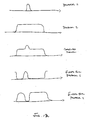
- the corresponding filtering to be employed are notched filters inversely constructed in accordance with the other devices' signals (see Fig. 12 ).
- devices 104a are to apply a notch filter, inversely formed in accordance with transmit signals of devices 104b, whereas, devices 104b are to apply a notch filter, inversely formed in accordance with transmit signals of devices 104a.
- Notch filters in general are known in the art, and will not be further described.
- network manager 1104 predicts when interference will occur, using the determined pseudo random pattern and interference frequency, 1116. Whenever, an interference is to occur, network manager 1104 preemptively notifies devices 104a and 104b to correspondingly apply their corresponding filtering, thereby allowing both devices 104a and 104b to operate without interference, 1118. The process continues, as long as there are wireless devices of both types 104a and 104b operating. [Likewise, the application of filtering by devices 104a may also be conditionally performed, only if the frequency is indeed the same as the interfering frequency.]
- network manager 1104 repeats the calibration periodically.
- network manager 1104 monitors actual interference between devices 104a and 104b, and tracks the mean time between interference.
- Network manager 1104 repeats the calibration, whenever the tracked mean time between interference drops below certain given performance level.
- devices 104a and 104a may also be practiced with minimal change to devices 104a and 104a, by equipping both types of network devices with the ability to responsively apply notch filtering.
- devices 104a may be additionally provided with simple combinatorial logic to effectuate the conditional application of notch filtering.
- wireless device 100 in addition to notifying the devices of the required filtering at 1114, wireless device 100 provides the devices with a collision map, such that the devices can self determine whether interference is to occur, and the appropriate filtering to be applied. In other words, operation 1116 is distributed to the devices, and operation 1118 is eliminated.
- wireless devices 104a and 104b of wireless networks 108a and 108b are shown, in accordance with another embodiment.
- the devices additionally operate in a complementary manner to proactively reduce interference among the devices.
- wireless devices 104a are assumed to employ a frequency hopping protocol.
- wireless devices 104a are subdivided into at least two subsets, with the devices of the two subsets employing successive frequencies in accordance with at least two corresponding pseudo random patterns.
- the frequency hopping protocol is Bluetooth
- each subset corresponds to a "piconet”. Note that even though for ease of understanding, only one device 104a is illustrated in each of the subset, the present invention may be practiced with each subset having one or more devices.
- the various subsets of devices 104a are operated in a synchronized manner (see Fig. 15 ).
- the synchronization is effectuated by synchronizing transmit and receive operations of the various subsets to a reference signal.
- the reference signal is provided by one of devices 104b. In other embodiments, the reference signal is provided by yet another device (not shown).
- devices 104b are also operated with transmit and receive operations aligned to the reference signal.
- wireless device 100 is further equipped to operate in a manner that is complementary to the synchronized operation of devices 104a and the aligned operation of devices 104b, to effectuate the desired reduction of interference among the devices.
- controller managers 106a and 106b are equipped to enable the two controller managers 106a and 106b to operate with aligned control clocks for the two protocols.
- controller manager or managers 106a and/or 106b are equipped such that when wireless device 100 joins wireless network 108b after having begun communication with devices 104a of at least one of the subsets, wireless device 100 would cause the two control clocks for the two protocols to be aligned incrementally.
- the incremental alignment is effectuated in a dependent manner, depending on the amount of misalignment with respect to a transmission time slot.
- the incremental alignment is effectuated by decrementing the start time of a transmission time slot by a predetermined amount for m successive transmission time slots if the amount of misalignment is less than half of the transmission time slot size, or by incrementing the start time of a transmission time slot by a predetermined amount for n successive transmission time slots if the amount of misalignment is less than half of the transmission time slot size.
- the start time of a transmission time slot of the protocol of network 108a can be adjusted successively by t micro seconds for m or n successively transmission time slots, depending on whether d is less than or equal to S/2 or greater than S/2.
- S is 625 micro seconds
- t is set to 8 micro seconds.
- the incremental alignment is repeated; however only after waiting for at least predetermined number of transmission time slots to "dampen oscillations". In one embodiment, the predetermined number of transmission time slots waited is 10. In other embodiments, different waiting periods may be used instead.
- wireless device 100 is communicatively coupled to devices 104a and devices 104b of wireless networks 108a and 108b respectively.
- Wireless device 100 performs transmits and receives of the two protocols, in a coordinated manner, to allow wireless device 100 to operate with devices 104a and devices 104b of wireless network 108a and 108b in accordance with the respective protocols at the same time.
- wireless device 100 is provided with a single wireless transceiver 1302, which includes joint signal transmit/receive section 1303, and a number of transmit and receive signals up/down conversion sections 1205 sharing joint signal transmit/receive section 1303.
- Wireless device 100 further includes controller/signal processing (C/SP) section 1306 to process data for transmission by wireless transceiver 1302, to process signals received by wireless transceiver 1302, and to control the data/signal processing operations as well as the operation of wireless transceiver 1302.
- C/SP controller/signal processing
- wireless device 100 is endowed with a network manager equipped with the capabilities earlier described referencing Figs. 8a-8b and 9a-9b, with or without the prospective interference anticipation for long packets.
- wireless device 100 is endowed with a network manager equipped with the capabilities earlier described referencing Figs. 10 and 11a -11b.
- wireless device 100 is endowed with the capabilities earlier described referencing Figs. 14 and 15 .
- the capabilities and methods of operations described referencing Figs 8a-8b and 9a-9b, Figs. 10 and 11a -11b, and Figs. 14-15 may be practiced with the multiple protocol wireless apparatus of the first parent application, number 09/408,725 , or the multiple protocol wireless apparatus of the second parent application.
Landscapes
- Engineering & Computer Science (AREA)
- Computer Networks & Wireless Communication (AREA)
- Signal Processing (AREA)
- Computer Security & Cryptography (AREA)
- Mobile Radio Communication Systems (AREA)
- Communication Control (AREA)
- Small-Scale Networks (AREA)
Claims (11)
- Groupement d'appareils réseautés comprenant:une première pluralité d'appareils (104a) incluant des premier et deuxième sous-ensembles réseautés sans fil ensemble, chaque appareil (104a) étant équipé pour communiquer sans fil en accord avec un premier protocole de saut de fréquence, les premier et deuxième sous-ensemble fonctionnant en accord avec un premier et un deuxième motif de saut de fréquence basé sur un premier et un deuxième motif pseudo aléatoire;une deuxième pluralité d'appareils (104b) réseautés sans fil ensemble, chaque appareil (104b) étant équipé pour communiquer sans fil en accord avec un deuxième protocole; etun appareil multi-protocole (100) équipé d'un premier et d'un deuxième émetteur-récepteur (102a, 102b) pour communiquer sans fil avec les première et deuxième pluralité d'appareils (104a, 104b) en accord avec les premier et deuxième protocoles respectivement, où les premier et deuxième sous-ensembles (104a) de la première pluralité d'appareils sont fonctionnellement synchronisés à un signal de référence, et la deuxième pluralité d'appareils (104b) sont fonctionnellement alignés au même signal de référence, et l'appareil multi-protocole (100) comprend une logique de commande pour fonctionner d'une manière qui est complémentaire à la synchronisation ainsi que l'alignement par rapport au signal de référence, et où la logique de commande comprend une logique pour effectuer l'alignement avec le signal de référence par incréments d'une manière dépendante d'une quantité de désalignement avec une intervalle de temps de transmission, pour réduire l'interférence entre les premiers et deuxièmes appareils (104a, 104b).
- Groupement d'appareils selon la revendication 1, où la logique décrémente un temps de départ d'intervalle de temps de transmission selon une quantité prédéterminée pour m intervalles de temps de transmission successifs si la quantité de désalignement est inférieure à la moitié d'une grandeur d'intervalle de temps de transmission.
- Groupement d'appareils selon la revendication 1, où la logique incrémente un temps de départ d'intervalle de temps de transmission selon une quantité prédéterminée pour n intervalles de temps de transmission successifs si la quantité de désalignement est supérieure à la moitié d'une grandeur d'intervalle de temps de transmission.
- Appareil (100) comprenant:une pluralité d'émetteurs-récepteurs sans fil (102a, 102b) pour transmettre et recevoir des signaux en accord avec un premier et un deuxième protocole, à et de premier et deuxième dispositifs de réseau (104a, 104b) d'un premier et deuxième réseau sans fil (108a, 108b) couplés en communication à l'appareil (100), les premiers dispositifs de réseau (104a) comprenant des premier et deuxième sous-ensembles qui transmettent et reçoivent en accord avec un premier et un deuxième motif de saut de fréquence basé sur un premier et un deuxième motif pseudo aléatoire d'une manière synchronisée, le premier protocole étant un protocole de saut de fréquence; etau moins un gestionnaire de commande (106a, 106b) couplé aux émetteurs-récepteurs sans fil (102a, 102b) pour commander et coordonner le fonctionnement des émetteurs-récepteurs sans fil (102a, 102b) d'une manière qui complète le fonctionnement synchronisé des premier et deuxième sous-ensembles des premiers dispositifs de réseau (104a) pour réduire l'interférence entre l'appareil (100) et les premier et deuxième dispositifs de réseau (104a, 104b), où au moins un gestionnaire de commande précité (106a, 106b) inclut une logique pour aligner les opérations de transmission et de réception desdits émetteurs-récepteurs sans fil (102a, 102b) avec un signal de référence contre lequel les premier et deuxième sous-ensembles des premiers dispositifs de réseau (104a) synchronisent les opérations, l'alignement au signal de référence étant effectué par incréments d'une manière dépendant de la quantité de désalignement avec une intervalle de temps de transmission.
- Appareil selon la revendication 4, où la logique décrémente un temps de départ d'intervalle de temps de transmission selon une quantité prédéterminée pour m intervalles de temps de transmission successifs si la quantité de désalignement est inférieure à la moitié d'une grandeur d'intervalle de temps de transmission.
- Appareil selon la revendication 4, où la logique incrémente un temps de départ d'intervalle de temps de transmission selon une quantité prédéterminée pour n intervalles de temps de transmission successifs si la quantité de désalignement est supérieure à la moitié d'une grandeur d'intervalle de temps de transmission.
- Appareil selon la revendication 4, où le premier protocole est bluetooth, et le deuxième protocole est un protocole sélectionné dans un groupe constitué d'un fonctionnement en saut de fréquence de 802,11, d'une séquence directe 802,11, 802,11a, 802,11b et RF Maison.
- Appareil selon la revendication 4, où l'appareil est un ordinateur ayant un facteur de forme sélectionné dans un groupe constitué d'un type de bureau, d'un type bloc-notes et d'un type d'ordinateur de poche.
- Procédé de fonctionnement d'un appareil (100) ayant un premier et un deuxième émetteur-récepteur sans fil (102a, 102b), le procédé comprenant les étapes consistant à:(a) commander au premier émetteur-récepteur sans fil (102a) de transmettre et de recevoir des données à et de premier et deuxième sous-ensembles de premiers dispositifs de réseau (104a) d'un premier réseau sans fil (108a) en accord avec un premier protocole qui est un protocole en saut de fréquence, et d'une manière qui est complémentaire à une manière de fonctionnement synchronisée des premier et deuxième sous-ensembles des premiers dispositifs de réseau (104a) en accord avec des premier et deuxième motifs de saut de fréquence basés sur des premier et deuxième motifs pseudo aléatoires respectivement; et(b) commander au deuxième émetteur-récepteur sans fil (102b) de transmettre et de recevoir des données à et de deuxièmes dispositifs de réseau (104b) d'un deuxième réseau sans fil (108b) en accord avec un deuxième protocole, et d'une manière qui est complémentaire à une manière de fonctionnement alignée des deuxièmes dispositifs de réseau (104b) au fonctionnement synchronisé des premier et deuxième sous-ensembles des premiers dispositifs de réseaux (104a), où les manières de commande complémentaires comprennent l'alignement des opérations de transmission et de réception des premier et deuxième émetteurs-récepteurs sans fil (102a, 102b) avec un signal de référence contre lequel les premier et deuxième sous-ensembles des premiers dispositifs de réseau (104a) synchronisent les opérations, l'alignement au signal de référence étant effectué par incréments d'une manière dépendant de la quantité de désalignement avec une intervalle de temps de transmission.
- Procédé selon la revendication 9, où l'alignement par incréments comprend la décrémentation d'un temps de départ d'intervalle de temps de transmission selon une quantité prédéterminée pour m intervalles de temps de transmission successifs si la quantité de désalignement est inférieure à la moitié d'une grandeur d'intervalle de temps de transmission.
- Procédé selon la revendication 9, où l'alignement par incréments comprend l'incrémentation d'un temps de départ d'intervalle de temps de transmission selon une quantité prédéterminée pour n intervalles de temps de transmission successifs si la quantité de désalignement est supérieure à une moitié d'une grandeur d'intervalle de temps de transmission.
Applications Claiming Priority (9)
| Application Number | Priority Date | Filing Date | Title |
|---|---|---|---|
| US560672 | 1990-07-31 | ||
| US09/408,725 US6894988B1 (en) | 1999-09-29 | 1999-09-29 | Wireless apparatus having multiple coordinated transceivers for multiple wireless communication protocols |
| US408725 | 1999-09-29 | ||
| US09/436,458 US6990082B1 (en) | 1999-11-08 | 1999-11-08 | Wireless apparatus having a transceiver equipped to support multiple wireless communication protocols |
| US436458 | 1999-11-08 | ||
| US439946 | 1999-11-12 | ||
| US09/439,946 US6600726B1 (en) | 1999-09-29 | 1999-11-12 | Multiple wireless communication protocol methods and apparatuses |
| US09/560,672 US6891857B1 (en) | 1999-09-29 | 2000-04-27 | Multiple wireless communication protocol methods and apparatuses including proactive reduction of interference |
| PCT/US2000/026807 WO2001024457A1 (fr) | 1999-09-29 | 2000-09-29 | Procede et appareil relatifs a un protocole multiple de telecommunications sans fil incluant une reduction proactive des interferences |
Publications (2)
| Publication Number | Publication Date |
|---|---|
| EP1216545A1 EP1216545A1 (fr) | 2002-06-26 |
| EP1216545B1 true EP1216545B1 (fr) | 2008-12-03 |
Family
ID=27503559
Family Applications (1)
| Application Number | Title | Priority Date | Filing Date |
|---|---|---|---|
| EP00967091A Expired - Lifetime EP1216545B1 (fr) | 1999-09-29 | 2000-09-29 | Procede et appareil relatifs a un protocole multiple de telecommunications sans fil incluant une reduction proactive des interferences |
Country Status (6)
| Country | Link |
|---|---|
| EP (1) | EP1216545B1 (fr) |
| JP (1) | JP2003510969A (fr) |
| AT (1) | ATE416532T1 (fr) |
| AU (1) | AU7734500A (fr) |
| DE (1) | DE60040994D1 (fr) |
| WO (1) | WO2001024457A1 (fr) |
Families Citing this family (13)
| Publication number | Priority date | Publication date | Assignee | Title |
|---|---|---|---|---|
| US6928266B1 (en) * | 1999-11-12 | 2005-08-09 | Intel Corporation | Wireless apparatus interference avoidance/resolution method and apparatuses |
| US7050452B2 (en) | 2000-10-06 | 2006-05-23 | Cognio, Inc. | Systems and methods for interference mitigation among multiple WLAN protocols |
| WO2002037706A1 (fr) | 2000-11-03 | 2002-05-10 | Aryya Communications, Inc. | Systeme emetteur-recepteur radio sans fil a bande large multi-protocole |
| US7190961B2 (en) * | 2001-10-18 | 2007-03-13 | Intel Corporation | Method for discovery and routing within mobile ad-hoc networks |
| US7668958B2 (en) | 2001-10-18 | 2010-02-23 | Intel Corporation | Method for discovery and routing using a priori knowledge in the form of application programme within mobile AD-HOC networks |
| KR100446614B1 (ko) * | 2001-08-23 | 2004-09-04 | 삼성전자주식회사 | 무선 데이타 통신망 제어 방법 및 장치 |
| US7848741B2 (en) | 2003-12-30 | 2010-12-07 | Kivekaes Kalle | Method and system for interference detection |
| US7643811B2 (en) | 2004-05-26 | 2010-01-05 | Nokia Corporation | Method and system for interference detection |
| US7486932B2 (en) | 2005-02-25 | 2009-02-03 | Nokia Corporation | Method and system for VoIP over WLAN to bluetooth headset using advanced eSCO scheduling |
| US7454171B2 (en) | 2005-02-25 | 2008-11-18 | Nokia Corporation | Method and system for VoIP over WLAN to Bluetooth headset using ACL link and sniff for aligned eSCO transmission |
| US7546142B2 (en) | 2005-09-29 | 2009-06-09 | Intel Corporation | Device, system and method of coordination among wireless transceivers |
| US10672252B2 (en) | 2015-12-31 | 2020-06-02 | Delta Faucet Company | Water sensor |
| DE102019204916A1 (de) * | 2019-04-05 | 2020-10-08 | Fraunhofer-Gesellschaft zur Förderung der angewandten Forschung e.V. | Systemkombination aus einem asynchronen und einem synchronen Funksystem |
Family Cites Families (1)
| Publication number | Priority date | Publication date | Assignee | Title |
|---|---|---|---|---|
| GB9725659D0 (en) | 1997-12-03 | 1998-02-04 | Nokia Mobile Phones Ltd | The LPRF system with frequency hopping extensions |
-
2000
- 2000-09-29 WO PCT/US2000/026807 patent/WO2001024457A1/fr active Application Filing
- 2000-09-29 JP JP2001527515A patent/JP2003510969A/ja not_active Abandoned
- 2000-09-29 AU AU77345/00A patent/AU7734500A/en not_active Abandoned
- 2000-09-29 EP EP00967091A patent/EP1216545B1/fr not_active Expired - Lifetime
- 2000-09-29 AT AT00967091T patent/ATE416532T1/de not_active IP Right Cessation
- 2000-09-29 DE DE60040994T patent/DE60040994D1/de not_active Expired - Lifetime
Also Published As
| Publication number | Publication date |
|---|---|
| JP2003510969A (ja) | 2003-03-18 |
| AU7734500A (en) | 2001-04-30 |
| WO2001024457A1 (fr) | 2001-04-05 |
| EP1216545A1 (fr) | 2002-06-26 |
| ATE416532T1 (de) | 2008-12-15 |
| DE60040994D1 (de) | 2009-01-15 |
Similar Documents
| Publication | Publication Date | Title |
|---|---|---|
| US6891857B1 (en) | Multiple wireless communication protocol methods and apparatuses including proactive reduction of interference | |
| US6600726B1 (en) | Multiple wireless communication protocol methods and apparatuses | |
| EP1216542B1 (fr) | Procedes et appareils relatifs a un protocole multiple de telecommunications incluant des considerations de qualite de services | |
| EP1216544B1 (fr) | Appareil sans fil equipe de multiples emetteurs-recepteurs coordonnes destines a de multiples protocoles de communication sans fil | |
| US6990082B1 (en) | Wireless apparatus having a transceiver equipped to support multiple wireless communication protocols | |
| EP1243099B1 (fr) | Procedes et appareils pour eviter ou resoudre l'interference des appareils sans fil | |
| EP1216545B1 (fr) | Procede et appareil relatifs a un protocole multiple de telecommunications sans fil incluant une reduction proactive des interferences | |
| US8086232B2 (en) | Time synchronized wireless method and operations | |
| US20020090914A1 (en) | Wireless communication apparatus, wireless communication method thereof, and wireless communication system employing the same | |
| US6816493B2 (en) | Method and apparatus employing a mediation device to facilitate communication among devices in an asynchronous communications network | |
| KR100436756B1 (ko) | 스니프모드에서 상호간의 데이터통신 시간을 절약할 수있는 무선통신 시스템 | |
| EP1216546B1 (fr) | Communication hertzienne simultanee vocale et de donnees utilisant des protocoles chevauchants | |
| JP5413269B2 (ja) | 無線通信装置、無線通信方法及びプログラム | |
| US8275390B1 (en) | System and method for detecting adjacent channel devices or interference | |
| RX | ‘06L’, CONTROLLER conmouenh M106! | |
| JPH10271091A (ja) | スペクトラム拡散無線通信装置 |
Legal Events
| Date | Code | Title | Description |
|---|---|---|---|
| PUAI | Public reference made under article 153(3) epc to a published international application that has entered the european phase |
Free format text: ORIGINAL CODE: 0009012 |
|
| 17P | Request for examination filed |
Effective date: 20020418 |
|
| AK | Designated contracting states |
Kind code of ref document: A1 Designated state(s): AT BE CH CY DE DK ES FI FR GB GR IE IT LI LU MC NL PT SE |
|
| AX | Request for extension of the european patent |
Free format text: AL;LT;LV;MK;RO;SI |
|
| RIN1 | Information on inventor provided before grant (corrected) |
Inventor name: ZHAO, XUDONG Inventor name: GINOSAR, RAN Inventor name: ZEHAVI, EPHRAIM Inventor name: NEVO, RON |
|
| 17Q | First examination report despatched |
Effective date: 20070731 |
|
| GRAP | Despatch of communication of intention to grant a patent |
Free format text: ORIGINAL CODE: EPIDOSNIGR1 |
|
| GRAS | Grant fee paid |
Free format text: ORIGINAL CODE: EPIDOSNIGR3 |
|
| GRAA | (expected) grant |
Free format text: ORIGINAL CODE: 0009210 |
|
| AK | Designated contracting states |
Kind code of ref document: B1 Designated state(s): AT BE CH CY DE DK ES FI FR GB GR IE IT LI LU MC NL PT SE |
|
| REG | Reference to a national code |
Ref country code: GB Ref legal event code: FG4D |
|
| REG | Reference to a national code |
Ref country code: CH Ref legal event code: EP |
|
| REG | Reference to a national code |
Ref country code: IE Ref legal event code: FG4D |
|
| REF | Corresponds to: |
Ref document number: 60040994 Country of ref document: DE Date of ref document: 20090115 Kind code of ref document: P |
|
| PG25 | Lapsed in a contracting state [announced via postgrant information from national office to epo] |
Ref country code: ES Free format text: LAPSE BECAUSE OF FAILURE TO SUBMIT A TRANSLATION OF THE DESCRIPTION OR TO PAY THE FEE WITHIN THE PRESCRIBED TIME-LIMIT Effective date: 20090314 |
|
| NLV1 | Nl: lapsed or annulled due to failure to fulfill the requirements of art. 29p and 29m of the patents act | ||
| PG25 | Lapsed in a contracting state [announced via postgrant information from national office to epo] |
Ref country code: FI Free format text: LAPSE BECAUSE OF FAILURE TO SUBMIT A TRANSLATION OF THE DESCRIPTION OR TO PAY THE FEE WITHIN THE PRESCRIBED TIME-LIMIT Effective date: 20081203 Ref country code: NL Free format text: LAPSE BECAUSE OF FAILURE TO SUBMIT A TRANSLATION OF THE DESCRIPTION OR TO PAY THE FEE WITHIN THE PRESCRIBED TIME-LIMIT Effective date: 20081203 |
|
| PG25 | Lapsed in a contracting state [announced via postgrant information from national office to epo] |
Ref country code: BE Free format text: LAPSE BECAUSE OF FAILURE TO SUBMIT A TRANSLATION OF THE DESCRIPTION OR TO PAY THE FEE WITHIN THE PRESCRIBED TIME-LIMIT Effective date: 20081203 |
|
| PG25 | Lapsed in a contracting state [announced via postgrant information from national office to epo] |
Ref country code: SE Free format text: LAPSE BECAUSE OF FAILURE TO SUBMIT A TRANSLATION OF THE DESCRIPTION OR TO PAY THE FEE WITHIN THE PRESCRIBED TIME-LIMIT Effective date: 20090303 Ref country code: PT Free format text: LAPSE BECAUSE OF FAILURE TO SUBMIT A TRANSLATION OF THE DESCRIPTION OR TO PAY THE FEE WITHIN THE PRESCRIBED TIME-LIMIT Effective date: 20090504 Ref country code: AT Free format text: LAPSE BECAUSE OF FAILURE TO SUBMIT A TRANSLATION OF THE DESCRIPTION OR TO PAY THE FEE WITHIN THE PRESCRIBED TIME-LIMIT Effective date: 20081203 |
|
| PLBE | No opposition filed within time limit |
Free format text: ORIGINAL CODE: 0009261 |
|
| STAA | Information on the status of an ep patent application or granted ep patent |
Free format text: STATUS: NO OPPOSITION FILED WITHIN TIME LIMIT |
|
| PG25 | Lapsed in a contracting state [announced via postgrant information from national office to epo] |
Ref country code: DK Free format text: LAPSE BECAUSE OF FAILURE TO SUBMIT A TRANSLATION OF THE DESCRIPTION OR TO PAY THE FEE WITHIN THE PRESCRIBED TIME-LIMIT Effective date: 20081203 |
|
| 26N | No opposition filed |
Effective date: 20090904 |
|
| PG25 | Lapsed in a contracting state [announced via postgrant information from national office to epo] |
Ref country code: MC Free format text: LAPSE BECAUSE OF NON-PAYMENT OF DUE FEES Effective date: 20090930 |
|
| REG | Reference to a national code |
Ref country code: CH Ref legal event code: PL |
|
| REG | Reference to a national code |
Ref country code: FR Ref legal event code: ST Effective date: 20100531 |
|
| PG25 | Lapsed in a contracting state [announced via postgrant information from national office to epo] |
Ref country code: FR Free format text: LAPSE BECAUSE OF NON-PAYMENT OF DUE FEES Effective date: 20090930 Ref country code: IE Free format text: LAPSE BECAUSE OF NON-PAYMENT OF DUE FEES Effective date: 20090929 |
|
| PG25 | Lapsed in a contracting state [announced via postgrant information from national office to epo] |
Ref country code: GR Free format text: LAPSE BECAUSE OF FAILURE TO SUBMIT A TRANSLATION OF THE DESCRIPTION OR TO PAY THE FEE WITHIN THE PRESCRIBED TIME-LIMIT Effective date: 20090304 Ref country code: LI Free format text: LAPSE BECAUSE OF NON-PAYMENT OF DUE FEES Effective date: 20090930 Ref country code: CH Free format text: LAPSE BECAUSE OF NON-PAYMENT OF DUE FEES Effective date: 20090930 |
|
| PG25 | Lapsed in a contracting state [announced via postgrant information from national office to epo] |
Ref country code: IT Free format text: LAPSE BECAUSE OF FAILURE TO SUBMIT A TRANSLATION OF THE DESCRIPTION OR TO PAY THE FEE WITHIN THE PRESCRIBED TIME-LIMIT Effective date: 20081203 |
|
| PG25 | Lapsed in a contracting state [announced via postgrant information from national office to epo] |
Ref country code: LU Free format text: LAPSE BECAUSE OF NON-PAYMENT OF DUE FEES Effective date: 20090929 |
|
| PG25 | Lapsed in a contracting state [announced via postgrant information from national office to epo] |
Ref country code: CY Free format text: LAPSE BECAUSE OF FAILURE TO SUBMIT A TRANSLATION OF THE DESCRIPTION OR TO PAY THE FEE WITHIN THE PRESCRIBED TIME-LIMIT Effective date: 20081203 |
|
| PGFP | Annual fee paid to national office [announced via postgrant information from national office to epo] |
Ref country code: DE Payment date: 20160920 Year of fee payment: 17 Ref country code: GB Payment date: 20160928 Year of fee payment: 17 |
|
| REG | Reference to a national code |
Ref country code: DE Ref legal event code: R119 Ref document number: 60040994 Country of ref document: DE |
|
| GBPC | Gb: european patent ceased through non-payment of renewal fee |
Effective date: 20170929 |
|
| PG25 | Lapsed in a contracting state [announced via postgrant information from national office to epo] |
Ref country code: GB Free format text: LAPSE BECAUSE OF NON-PAYMENT OF DUE FEES Effective date: 20170929 Ref country code: DE Free format text: LAPSE BECAUSE OF NON-PAYMENT OF DUE FEES Effective date: 20180404 |