EP1215795A2 - Apparatus for and method of detecting charge state of vehicle battery - Google Patents
Apparatus for and method of detecting charge state of vehicle battery Download PDFInfo
- Publication number
- EP1215795A2 EP1215795A2 EP01309562A EP01309562A EP1215795A2 EP 1215795 A2 EP1215795 A2 EP 1215795A2 EP 01309562 A EP01309562 A EP 01309562A EP 01309562 A EP01309562 A EP 01309562A EP 1215795 A2 EP1215795 A2 EP 1215795A2
- Authority
- EP
- European Patent Office
- Prior art keywords
- battery
- charge state
- state
- vehicle
- equilibrium
- Prior art date
- Legal status (The legal status is an assumption and is not a legal conclusion. Google has not performed a legal analysis and makes no representation as to the accuracy of the status listed.)
- Granted
Links
Images




Classifications
-
- G—PHYSICS
- G01—MEASURING; TESTING
- G01R—MEASURING ELECTRIC VARIABLES; MEASURING MAGNETIC VARIABLES
- G01R31/00—Arrangements for testing electric properties; Arrangements for locating electric faults; Arrangements for electrical testing characterised by what is being tested not provided for elsewhere
- G01R31/36—Arrangements for testing, measuring or monitoring the electrical condition of accumulators or electric batteries, e.g. capacity or state of charge [SoC]
- G01R31/3644—Constructional arrangements
- G01R31/3648—Constructional arrangements comprising digital calculation means, e.g. for performing an algorithm
-
- H—ELECTRICITY
- H02—GENERATION; CONVERSION OR DISTRIBUTION OF ELECTRIC POWER
- H02J—ELECTRIC POWER NETWORKS; CIRCUIT ARRANGEMENTS OR SYSTEMS FOR SUPPLYING OR DISTRIBUTING ELECTRIC POWER; SYSTEMS FOR STORING ELECTRIC ENERGY
- H02J7/00—Circuit arrangements for charging or discharging batteries or for supplying loads from batteries
- H02J7/80—Circuit arrangements for charging or discharging batteries or for supplying loads from batteries including monitoring or indicating arrangements
- H02J7/82—Control of state of charge [SOC]
-
- H—ELECTRICITY
- H02—GENERATION; CONVERSION OR DISTRIBUTION OF ELECTRIC POWER
- H02J—ELECTRIC POWER NETWORKS; CIRCUIT ARRANGEMENTS OR SYSTEMS FOR SUPPLYING OR DISTRIBUTING ELECTRIC POWER; SYSTEMS FOR STORING ELECTRIC ENERGY
- H02J7/00—Circuit arrangements for charging or discharging batteries or for supplying loads from batteries
- H02J7/14—Circuit arrangements for charging or discharging batteries or for supplying loads from batteries for charging batteries from dynamo-electric generators driven at varying speed, e.g. on vehicle
Definitions
- the present invention relates to an apparatus for and a method of detecting the charge state of a vehicle battery that can be charged/discharged.
- a battery that can be charged/discharged is normally mounted on a vehicle to function as a power supply source from which power is supplied to an electrical load of the vehicle.
- This battery is charged by a generator while the vehicle travels.
- the electrical load of the vehicle is driven by the power charged in the battery.
- battery depletion occurs due to an insufficient quantity of power in the battery if the quantity of power charged in the battery becomes low after power is discharged to the electrical load from the battery or if the battery becomes degraded.
- the vehicle is equipped with a warning lamp which warns that the quantity of power charged in the battery has become low and a meter which indicates the charge quantity representing the quantity of power stored in the battery.
- the following method is normally adopted in the earlier technology to detect the charge state of a battery. Namely, the battery charge state is ascertained by measuring the voltage at the battery, the battery charge state thus ascertained is set as an initial value and the battery charge state is subsequently calculated as necessary by totalizing the charge / discharge quantity as the vehicle travels.
- Japanese Laid-Open Patent Publication No. H 8-106927 discloses an apparatus for detecting the charge state of a vehicle battery by addressing the problem discussed above.
- This apparatus in the prior art for detecting the vehicle battery charge state is provided with a timer that counts the length of time elapsing after the battery stops charging, and it measures the voltage at the battery after it is detected by the timer that a predetermined length of time after which the potential is assumed to enter a state of equilibrium has elapsed. As a result, the battery charge state is detected with a high degree of accuracy.
- the vehicle battery charge state detection apparatus in the prior art poses a problem in that the efficiency with which the battery charge state is detected is poor. This problem is now explained in detail in reference to FIGS. 6 ⁇ 8.
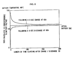
- FIG. 6 shows the relationship ascertained through testing, which manifests between the battery charge state (SOC: state of charge) calculated in conformance to the battery voltage following a battery charge / discharge and the length of time elapsing after the battery charge / discharge with the battery temperature set to 0 °C.
- SOC state of charge
- the battery charge and discharge are both implemented by using a 60 (A) current over 5 seconds.
- A 60
- FIG. 6 clearly indicates, the length of time to elapse before the battery charge state calculated based upon the battery voltage matches the actual battery charge state following the battery charge differs from the length of time to elapse before the calculated battery charge state matches the actual battery charge state following the battery discharge.
- the length of time to elapse following the battery charge before the battery voltage enters a state of equilibrium does not match the length of time to elapse following the battery discharge before the battery voltage enters a state of equilibrium
- the length of time to elapse following the battery charge before the calculated battery charge state matches the actual battery charge state, too, is different from the length of time to elapse following the battery discharge before the calculated battery charge state matches the actual battery charge state.
- FIGS. 7 and 8 present the results of identical tests conducted by varying the battery temperature.
- FIG. 7 presents the results of a test conducted by setting the battery temperature at 25°C
- FIG. 8 presents the results of a test conducted by setting the battery temperature at 40°C.
- the results presented in FIGS. 6 ⁇ 8 clearly indicate, the length of time to elapse following the battery charge / discharge before the battery voltage enters a state of equilibrium changes depending upon the battery temperature.
- the length of time to elapse following the battery charge or discharge before the battery potential enters a state of equilibrium i.e., the length of time to elapse before the battery charge state can be calculated with accuracy, changes depending upon conditions including the battery temperature and whether the battery has undergone a charge or discharged. Accordingly, the time setting at the timer mentioned earlier must be the maximum value selected by taking into consideration these conditions. However, this may lead to a problem in that the battery charge state can only be detected after the length of time set at the timer elapses even when the battery potential has already entered equilibrium. In other words, the efficiency with which the battery charge state is detected may be compromised.
- a vehicle battery charge state detection apparatus comprises a charge state detection means for detecting the charge state of a vehicle battery which can be charged and discharged, a battery temperature detection means for detecting the temperature of the battery, an ambient temperature detection means for detecting the ambient temperature and an equilibrium judging means for judging as to whether or not the battery potential is in a state of equilibrium or in a state of non-equilibrium based upon the battery temperature detected by the battery temperature detection means and the ambient temperature detected by the ambient temperature detection means.
- the charge state detection means detects the battery charge state if the equilibrium judging means judges that the battery potential is in a state of equilibrium but does not detect the battery charge state if the equilibrium judging means judges that the battery potential is in a state of non-equilibrium.
- the battery temperature and the ambient temperature are detected, it is judged as to whether the battery potential is in a state of equilibrium or non-equilibrium based upon the detected battery temperature and ambient temperature; and the battery charge state is detected if the battery potential is in a state of equilibrium whereas the battery charge state is not detected if the battery potential is determined to be in a state of non-equilibrium.
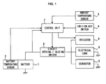
- FIG. 1 is a block diagram showing the structure adopted in an embodiment of the vehicle battery charge state detection apparatus according to the present invention.
- a battery 1 that can be charged / discharged is mounted in a vehicle.
- the battery 1 is connected to an electrical load 6 which may be a lamp or a motor fan in the vehicle, a generator 5, and an indicator 9 that indicates the charge state of the battery 1.
- the battery 1 is charged by utilizing the generator 5.
- the electrical load 6 and the indicator 9 are driven by the power supplied from the battery 1.
- a circuit opening / closing switch 8 is provided between the battery 1 and the electrical load 6, the generator 5,and the indicator 9.
- the circuit opening / closing switch 8 electrically connects the battery 1 to the electrical load 6 and the generator 5 by closing the circuit in response to a switch close signal provided by the control unit 7. In addition, it electrically disconnects the battery 1 from the electrical load 6 and the generator 5 by opening the circuit in response to a switch open signal provided by the control unit 7.
- a battery temperature sensor 2 which may be provided in the vicinity of the battery 1, for instance, detects the temperature of the battery 1.
- An ambient temperature sensor 3 detects the ambient temperature around the battery (1).
- An ignition key switch 4 is turned on when the driver inserts a vehicle key (not shown) at an ignition key cylinder and turns the vehicle key to the ON position and is turned off when the vehicle key (not shown) is turned to the OFF position.
- the ignition key switch 4 transmits an ON signal indicating an ON state and an OFF signal indicating an OFF state to the control unit 7.
- the indicator 9 signals the charge state of the battery 1 to the driver.
- the control unit 7 is connected to the battery 1, the battery temperature sensor 2, the ambient temperature sensor 3, the ignition key switch 4, the circuit opening / closing switch 8, and the indicator 9.
- the control unit 7 detects the charge state of the battery 1 based upon the voltage at the battery 1, the battery temperature detected by the battery temperature sensor 2,and the ambient temperature detected by the ambient temperature sensor 3. The battery charge state thus detected is transmitted to the indicator 9.
- the control unit 7 also engages in control for opening / closing the circuit opening / closing switch 8.
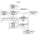
- the control unit 7 includes a temperature detection circuit 10, a battery voltage detection circuit 11, a memory unit 12, a comparator unit 13 and an arithmetic operation unit 14.
- the battery voltage detection circuit 11 detects the voltage at the battery 1 and converts the voltage at the battery 1 that has been detected to a battery voltage value to be used in an arithmetic operation.
- the temperature detection circuit 10 converts the battery temperature detected by the battery temperature sensor 2 and the ambient temperature detected by the ambient temperature sensor 3 to a battery temperature value and an ambient temperature value respectively to be utilized in the arithmetic operation.
- the memory unit 12 stores in memory the battery temperature value obtained through the conversion performed at the temperature detection circuit 10 and the battery voltage value detected at the battery voltage detection circuit 11, and also stores in memory the battery charge state transmitted from the arithmetic operation unit 14.
- the battery charge state stored in the memory unit 12 is transmitted to the indicator 9 in response to a command issued by the arithmetic operation unit 14.
- the comparator unit 13 reads out the battery voltage value stored in the memory unit 12 and the battery voltage value detected at the battery voltage detection circuit 11 and judges as to whether the battery 1 has undergone a charge or discharge by comparing the two battery voltage values thus read out.
- the judging results are transmitted to the arithmetic operation unit 14.
- the arithmetic operation unit 14 reads out the battery temperature value and the battery voltage value stored in the memory unit 12, and judges as to whether the battery potential is in a state of equilibrium or in a state of non-equilibrium based upon the battery temperature value and the battery voltage value that have been read out, the judging results transmitted from the comparator unit 13 and the battery temperature value and the ambient temperature value read out from the temperature detection circuit 10.
- the arithmetic operation unit 14 detects the battery charge state and transmits the detected charge state to the memory unit 12, whereas the arithmetic operation unit 14 does not detect the battery charge state if the battery potential is detected to be in a state of non-equilibrium.
- FIG. 3 shows the details of the control implemented by the control unit 7 when the driver stops the vehicle, i.e. when the driver stops the engine.
- step S101 it is judged as to whether or not the driver has stopped the vehicle, i.e. as to whether or not the ignition key switch 4 has been switched from an ON state to an OFF state. If the driver has turned the vehicle key (not shown) to turn off the ignition key switch 4, an OFF signal is provided to the arithmetic operation unit 14. Upon receiving the OFF signal at the arithmetic operation unit 14, it is decided that the ignition key switch 4 has been switched from the ON state to the OFF state and the operation proceeds to step S102. The arithmetic operation unit 14 transmits a switch open signal to the circuit opening / closing switch 8 in step S102. Upon receiving the switch open signal, the circuit opening / closing switch 8 electrically disconnects the battery 1 from the generator 5 and the electrical load 6 by opening the circuit.
- step S103 the temperature detection circuit 10 converts the battery temperature detected at the battery temperature sensor 2 to a battery temperature value T1.
- the battery voltage detection circuit 11 detects a battery voltage value V1.
- step S104 the battery temperature value T1 and the battery voltage value V1 detected in step S103 are stored in the memory unit 12.
- the control for detecting the battery charge state ends for the time being.
- step S201 it is judged as to whether or not the driver has started the vehicle, i.e., as to whether or not the ignition key switch 4 has exited the OFF state and entered the ON state. If the driver has turned the vehicle key (not shown) to turn on the ignition key switch 4, an ON signal is provided to the arithmetic operation unit 14. Upon receiving the ON signal at the arithmetic operation unit 14, it is decided that the ignition key switch 4 has been switched from the OFF state to the ON state and the operation proceeds to step S202.
- step S202 the battery voltage detection circuit 11 detects a battery voltage value V2 before the operation proceeds to step S203.
- step S203 the comparator unit 13 reads out the battery voltage value V1 that was stored in the memory unit 12 when the vehicle was stopped previously. Once the battery voltage value V1 is read out, the operation proceeds to step S204.
- step S204 the comparator unit 13 compares the battery voltage value V2 detected at the battery voltage detection circuit 11 with the battery voltage value V1 read out from the memory unit 12. If it is decided that the battery voltage value V1 is smaller than the battery voltage value V2, the operation proceeds to step S205.
- step S205 the comparator unit 13 decides that the battery 1 has undergone a charge and provides the results of the decision to the arithmetic operation unit 14 before the operation proceeds to step S206.
- step S206 the arithmetic operation unit 14 reads the battery temperature value T1 that was stored in the memory unit 12 when the vehicle was last stopped (step S104 in FIG.3). Once the battery temperature value T1 is read, the operation proceeds to step S207.
- step S207 the arithmetic operation unit 14 calculates a judging value Tc which is to be detailed later.
- step S204 If, on the other hand, it is decided in step S204 that the battery voltage value V1 is larger than the battery voltage value V2, the operation proceeds to step S208.
- step S208 the comparator unit 13 decides that the battery 1 has undergone a discharge and provides the results of the decision to the arithmetic operation unit 14 before the operation proceeds to step S209.
- step S209 the arithmetic operation unit 14 reads the battery temperature value T1 that was stored in the memory unit 12 when the vehicle was last stopped (step S104 in FIG.3). Once the battery temperature value T1 is read, the operation proceeds to step S210.
- step S210 the arithmetic operation unit 14 calculates a judging value Td which is to be detailed later.
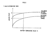
- the judging value Tc or Td is calculated based upon the battery temperature value T1 read in step S206 or step S209 and the table shown in FIG. 5. After calculating the judging value Tc or Td in step S207 or step S210, the operation proceeds to step S211. It is to be noted that the judging value Tc or Td is utilized in the processing implemented in step S212 which is to be detailed later.
- step S211 the temperature detection circuit 10 detects a battery temperature value T2 which is the current battery temperature value and an ambient temperature value T0 that is the current ambient temperature value.
- the arithmetic operation unit 14 reads the battery temperature value T2 and the ambient temperature value T0 from the temperature detection circuit 10 and then the operation proceeds to step S212.
- step S208 If, on the other hand it is decided in step S208 that the battery 1 has undergone a discharge, it is judged as to whether or not the relationship expressed in the following expression (2) is achieved. T2 - T0 ⁇ ⁇
- step S213 the arithmetic operation unit 14 decides that the battery potential is in a state of equilibrium and the operation proceeds to step S215.
- step S215 the arithmetic operation unit 14 calculates the battery charge state in correspondence to the battery voltage value V2. The results of the calculation are transmitted to the memory unit 12.
- step S216 the memory unit 12 updates the charge state by storing in memory the battery charge state transmitted from the arithmetic operation unit 14.
- step S217 since the charge state of the battery 1 is updated only if the potential at the battery 1 is in a state of equilibrium, it is ensured that the charge state of the battery 1 stored in the memory unit 12 is an accurate value at all times. Once the charge state of the battery 1 is stored in memory, the operation proceeds to step S217.
- step S212 If, on the other hand, it is decided in step S212 that the relationship expressed in expression (1) or (2) is not achieved, the operation proceeds to step S214.
- the battery 1 generates heat when the potential at the battery 1 is in a state of non-equilibrium. Accordingly, if the difference between the battery temperature value T2 and the ambient temperature value T0 is larger than the judging value Tc or Td, the potential at the battery 1 is determined to be in a state of non-equilibrium. Namely, in step S214, the arithmetic operation unit 14 decides that the battery potential is in a state of non-equilibrium and the operation proceeds to step S217.
- step S217 the battery charge state stored in step S216 is transmitted from the memory unit 12 to the indicator 9.
- an accurate charge state of the battery 1 can be indicated to the driver.
- the arithmetic operation unit 14 transmits a switch close signal to the circuit opening / closing switch 8. Upon receiving the switch close signal, the circuit opening / closing switch 8 closes the circuit.
- the vehicle battery charge state detection apparatus detects the battery charge state as summarized below.
- the temperature detection circuit 10 detects the battery temperature value T1 and the battery voltage detection circuit 11 detects the battery voltage value V1, both of which are then stored in the memory unit 12.
- the battery voltage detection circuit 11 detects the battery voltage value V2.
- the comparator unit 13 judges as to whether the battery 1 has undergone a charge or discharge by comparing the battery voltage value V1 read out from the memory unit 12 with the battery voltage value V2.
- the battery temperature value T1 stored in the memory unit 12 is read out and the judging value Tc or Td is calculated based upon the battery temperature value T1 thus read out.
- the arithmetic operation unit 14 judges as to whether the battery potential is in a state of equilibrium or in a state of non-equilibrium based upon the current battery temperature value T2, the current ambient temperature value T0 and the judging value Tc or Td. Only if it is decided that the battery potential is in a state of equilibrium, the arithmetic operation unit 14 detects the charge state of the battery 1 in correspondence to the battery voltage value V2 and updates the charge state of battery 1 stored in the memory unit 12. The charge state of the battery 1 stored in the memory unit 12 is transmitted to the indicator 9.
- the timer provided in the apparatus for detecting the battery charge state in the prior art described earlier is no longer required.
- the battery charge state can be detected with a high degree of accuracy with no timer consuming power from the battery 1.
- a reduction in the production costs is achieved,since it is not necessary to provide the timer.
- the arithmetic operation unit 14 decides that the potential at the battery 1 is in a state of equilibrium if the difference between the battery temperature value T2 and the ambient temperature value T0 is equal to or smaller than the judging value Tc or Td and decides that the potential at the battery 1 is in a state of non-equilibrium if the difference between the battery temperature value T2 and the ambient temperature value T0 is larger than the judging value Tc or Td. Since the judging values Tc and Td are each calculated based upon the battery temperature value T1, the charge state of the battery 1 can be detected with a high degree of accuracy within the shortest possible length of time following the charge / discharge of the battery 1 even when the battery temperature fluctuates.
- the judging value Tc or Td is calculated based upon the battery temperature value T1 detected when the driver last stopped the vehicle and the battery temperature value T2 and the ambient temperature value T0 are detected when the driver restarts the vehicle. Consequently, the charge state of the battery 1 can be detected as the driver restarts the vehicle. Thus, it is ensured that an accurate charge state of the battery can be detected whenever the vehicle is started.
- the judging value Tc or Td is calculated based upon the results of the comparison of the battery voltage value V1 detected when the driver last stopped the vehicle and the battery voltage value V2 detected when the driver restarts the vehicle in addition to the battery temperature value T1.
- the judging value Tc or Td can be calculated with an even higher degree of accuracy to achieve an even more accurate detection of the charge state of the battery 1.
- the present invention is not limited to the embodiment presented above.
- a table other than that shown in FIG. 5 may be used to calculate the judging values Tc and Td.
- the charge state of the battery 1 may be indicated to the driver with a buzzer (not shown) instead of the indicator 9.
Landscapes
- Engineering & Computer Science (AREA)
- Power Engineering (AREA)
- Physics & Mathematics (AREA)
- General Physics & Mathematics (AREA)
- Secondary Cells (AREA)
- Charge And Discharge Circuits For Batteries Or The Like (AREA)
- Tests Of Electric Status Of Batteries (AREA)
Abstract
Description
- The present invention relates to an apparatus for and a method of detecting the charge state of a vehicle battery that can be charged/discharged.
- A battery that can be charged/discharged is normally mounted on a vehicle to function as a power supply source from which power is supplied to an electrical load of the vehicle. This battery is charged by a generator while the vehicle travels. The electrical load of the vehicle is driven by the power charged in the battery. However, battery depletion occurs due to an insufficient quantity of power in the battery if the quantity of power charged in the battery becomes low after power is discharged to the electrical load from the battery or if the battery becomes degraded. In order to ensure that such battery depletion is prevented by giving the driver advance warning that battery depletion is imminent, the vehicle is equipped with a warning lamp which warns that the quantity of power charged in the battery has become low and a meter which indicates the charge quantity representing the quantity of power stored in the battery.
- The following method is normally adopted in the earlier technology to detect the charge state of a battery. Namely, the battery charge state is ascertained by measuring the voltage at the battery, the battery charge state thus ascertained is set as an initial value and the battery charge state is subsequently calculated as necessary by totalizing the charge / discharge quantity as the vehicle travels.
- However, since a battery manifests characteristics whereby the potential achieves a state of equilibrium when a specific length of time has elapsed following a battery charge / discharge, an accurate battery charge state cannot be detected until the specific length of time elapses following the battery charge / discharge. For this reason, if the battery voltage is measured before the specific length of time elapses following a battery charge / discharge, an accurate battery charge state cannot be detected based upon the measured voltage. In such a case, a problem arises in that an error between the actual battery charge state and the detected battery charge state manifests. In other words, even when the quantity of power actually charged in the battery is nearing zero, the warning lamp or the meter may indicate that there is still some margin of safety left with regard to the battery charge quantity. In addition, the warning lamp or the meter may erroneously indicate that the battery charge quantity is nearing zero even when a comfortable margin remains with regard to the actual battery charge quantity.
- Japanese Laid-Open Patent Publication No. H 8-106927 discloses an apparatus for detecting the charge state of a vehicle battery by addressing the problem discussed above. This apparatus in the prior art for detecting the vehicle battery charge state is provided with a timer that counts the length of time elapsing after the battery stops charging, and it measures the voltage at the battery after it is detected by the timer that a predetermined length of time after which the potential is assumed to enter a state of equilibrium has elapsed. As a result, the battery charge state is detected with a high degree of accuracy.
- However, the vehicle battery charge state detection apparatus in the prior art poses a problem in that the efficiency with which the battery charge state is detected is poor. This problem is now explained in detail in reference to FIGS. 6 ∼ 8.
- FIG. 6 shows the relationship ascertained through testing, which manifests between the battery charge state (SOC: state of charge) calculated in conformance to the battery voltage following a battery charge / discharge and the length of time elapsing after the battery charge / discharge with the battery temperature set to 0 °C. The battery charge and discharge are both implemented by using a 60 (A) current over 5 seconds. As FIG. 6 clearly indicates, the length of time to elapse before the battery charge state calculated based upon the battery voltage matches the actual battery charge state following the battery charge differs from the length of time to elapse before the calculated battery charge state matches the actual battery charge state following the battery discharge. Namely, since the length of time to elapse following the battery charge before the battery voltage enters a state of equilibrium does not match the length of time to elapse following the battery discharge before the battery voltage enters a state of equilibrium, the length of time to elapse following the battery charge before the calculated battery charge state matches the actual battery charge state, too, is different from the length of time to elapse following the battery discharge before the calculated battery charge state matches the actual battery charge state.
- FIGS. 7 and 8 present the results of identical tests conducted by varying the battery temperature. FIG. 7 presents the results of a test conducted by setting the battery temperature at 25°C, whereas FIG. 8 presents the results of a test conducted by setting the battery temperature at 40°C. As the results presented in FIGS. 6 ∼ 8 clearly indicate, the length of time to elapse following the battery charge / discharge before the battery voltage enters a state of equilibrium changes depending upon the battery temperature.
- In other words, the length of time to elapse following the battery charge or discharge before the battery potential enters a state of equilibrium, i.e., the length of time to elapse before the battery charge state can be calculated with accuracy, changes depending upon conditions including the battery temperature and whether the battery has undergone a charge or discharged. Accordingly, the time setting at the timer mentioned earlier must be the maximum value selected by taking into consideration these conditions. However, this may lead to a problem in that the battery charge state can only be detected after the length of time set at the timer elapses even when the battery potential has already entered equilibrium. In other words, the efficiency with which the battery charge state is detected may be compromised.
- It would be desirable to be able to provide an apparatus for and a method of detecting the charge state of a vehicle battery, that make it possible to accurately detect the battery charge state within the shortest possible length of time corresponding to the battery conditions.
- A vehicle battery charge state detection apparatus according to the present invention comprises a charge state detection means for detecting the charge state of a vehicle battery which can be charged and discharged, a battery temperature detection means for detecting the temperature of the battery, an ambient temperature detection means for detecting the ambient temperature and an equilibrium judging means for judging as to whether or not the battery potential is in a state of equilibrium or in a state of non-equilibrium based upon the battery temperature detected by the battery temperature detection means and the ambient temperature detected by the ambient temperature detection means. The charge state detection means detects the battery charge state if the equilibrium judging means judges that the battery potential is in a state of equilibrium but does not detect the battery charge state if the equilibrium judging means judges that the battery potential is in a state of non-equilibrium.
- In the method of detecting the charge state of a vehicle battery which can be charged / discharged, the battery temperature and the ambient temperature are detected, it is judged as to whether the battery potential is in a state of equilibrium or non-equilibrium based upon the detected battery temperature and ambient temperature; and the battery charge state is detected if the battery potential is in a state of equilibrium whereas the battery charge state is not detected if the battery potential is determined to be in a state of non-equilibrium.
-
- FIG. 1 is a block diagram illustrating the structure adopted in an embodiment of the vehicle battery charge state detection apparatus according to the present invention;
- FIG. 2 is a block diagram illustrating the structure
adopted in the
control unit 7 in the embodiment; - FIG. 3 is a flowchart of the processing implemented by
the
control unit 7 after the ignition key is turned off; - FIG. 4 is a flowchart of the processing implemented by
the
control unit 7 after the ignition key is turned on; - FIG. 5 shows a judging value determining table utilized to calculate the judging value Tc or Td;
- FIG. 6 shows the relationship ascertained through testing, which manifests between the battery charge state (SOC) calculated based upon the battery voltage and the length of time elapsing following a charge / discharge when a 60A current is charged / discharged over 5 seconds with the battery temperature set to 0°C;
- FIG. 7 shows the relationship ascertained through testing, which manifests between the battery charge state (SOC) calculated based upon the battery voltage and the length of time elapsing following a charge / discharge when a 60A current is charged / discharged over 5 seconds with the battery temperature set to 25 °C; and
- FIG. 8 shows the relationship ascertained through testing, which manifests between the battery charge state (SOC) calculated based upon the battery voltage and the length of time elapsing following a charge / discharge when a 60A current is charged / discharged over 5 seconds with the battery temperature set to 40°C.
-
- The following is a detailed explanation of an embodiment of the vehicle battery charge state detection apparatus according to the present invention, given in reference to FIGS. 1 through 5. FIG. 1 is a block diagram showing the structure adopted in an embodiment of the vehicle battery charge state detection apparatus according to the present invention. A
battery 1 that can be charged / discharged is mounted in a vehicle. Thebattery 1 is connected to an electrical load 6 which may be a lamp or a motor fan in the vehicle, agenerator 5, and anindicator 9 that indicates the charge state of thebattery 1. Thebattery 1 is charged by utilizing thegenerator 5. The electrical load 6 and theindicator 9 are driven by the power supplied from thebattery 1. - A circuit opening /
closing switch 8 is provided between thebattery 1 and the electrical load 6, thegenerator 5,and theindicator 9. The circuit opening /closing switch 8 electrically connects thebattery 1 to the electrical load 6 and thegenerator 5 by closing the circuit in response to a switch close signal provided by thecontrol unit 7. In addition, it electrically disconnects thebattery 1 from the electrical load 6 and thegenerator 5 by opening the circuit in response to a switch open signal provided by thecontrol unit 7. - A
battery temperature sensor 2, which may be provided in the vicinity of thebattery 1, for instance, detects the temperature of thebattery 1. Anambient temperature sensor 3 detects the ambient temperature around the battery (1). An ignition key switch 4 is turned on when the driver inserts a vehicle key (not shown) at an ignition key cylinder and turns the vehicle key to the ON position and is turned off when the vehicle key (not shown) is turned to the OFF position. The ignition key switch 4 transmits an ON signal indicating an ON state and an OFF signal indicating an OFF state to thecontrol unit 7. By detecting the ON/OFF state of the ignition key switch 4, a time point at which the driver stops the vehicle (the engine) and a time point at which the driver starts the vehicle (the engine) can be detected with a high degree of accuracy. - The
indicator 9 signals the charge state of thebattery 1 to the driver. Theindicator 9, which may be provided in, for instance, the speedometer, signals the charge state of thebattery 1 transmitted from thecontrol unit 7. Thecontrol unit 7 is connected to thebattery 1, thebattery temperature sensor 2, theambient temperature sensor 3, the ignition key switch 4, the circuit opening /closing switch 8, and theindicator 9. Thecontrol unit 7 detects the charge state of thebattery 1 based upon the voltage at thebattery 1, the battery temperature detected by thebattery temperature sensor 2,and the ambient temperature detected by theambient temperature sensor 3. The battery charge state thus detected is transmitted to theindicator 9. Thecontrol unit 7 also engages in control for opening / closing the circuit opening /closing switch 8. - The structure adopted in the
control unit 7 is now explained in reference to FIG. 2. Thecontrol unit 7 includes atemperature detection circuit 10, a battery voltage detection circuit 11, amemory unit 12, acomparator unit 13 and anarithmetic operation unit 14. The battery voltage detection circuit 11 detects the voltage at thebattery 1 and converts the voltage at thebattery 1 that has been detected to a battery voltage value to be used in an arithmetic operation. Thetemperature detection circuit 10 converts the battery temperature detected by thebattery temperature sensor 2 and the ambient temperature detected by theambient temperature sensor 3 to a battery temperature value and an ambient temperature value respectively to be utilized in the arithmetic operation. - The
memory unit 12 stores in memory the battery temperature value obtained through the conversion performed at thetemperature detection circuit 10 and the battery voltage value detected at the battery voltage detection circuit 11, and also stores in memory the battery charge state transmitted from thearithmetic operation unit 14. The battery charge state stored in thememory unit 12 is transmitted to theindicator 9 in response to a command issued by thearithmetic operation unit 14. - The
comparator unit 13 reads out the battery voltage value stored in thememory unit 12 and the battery voltage value detected at the battery voltage detection circuit 11 and judges as to whether thebattery 1 has undergone a charge or discharge by comparing the two battery voltage values thus read out. The judging results are transmitted to thearithmetic operation unit 14. Thearithmetic operation unit 14 reads out the battery temperature value and the battery voltage value stored in thememory unit 12, and judges as to whether the battery potential is in a state of equilibrium or in a state of non-equilibrium based upon the battery temperature value and the battery voltage value that have been read out, the judging results transmitted from thecomparator unit 13 and the battery temperature value and the ambient temperature value read out from thetemperature detection circuit 10. If it is decided that the battery potential is in a state of equilibrium, thearithmetic operation unit 14 detects the battery charge state and transmits the detected charge state to thememory unit 12, whereas thearithmetic operation unit 14 does not detect the battery charge state if the battery potential is detected to be in a state of non-equilibrium. - Now, the details of the control implemented by the
control unit 7 are explained in reference to the flowcharts presented in FIGS. 3 and 4. The flowchart in FIG. 3 shows the details of the control implemented by thecontrol unit 7 when the driver stops the vehicle, i.e. when the driver stops the engine. - In step S101, it is judged as to whether or not the driver has stopped the vehicle, i.e. as to whether or not the ignition key switch 4 has been switched from an ON state to an OFF state. If the driver has turned the vehicle key (not shown) to turn off the ignition key switch 4, an OFF signal is provided to the
arithmetic operation unit 14. Upon receiving the OFF signal at thearithmetic operation unit 14, it is decided that the ignition key switch 4 has been switched from the ON state to the OFF state and the operation proceeds to step S102. Thearithmetic operation unit 14 transmits a switch open signal to the circuit opening /closing switch 8 in step S102. Upon receiving the switch open signal, the circuit opening /closing switch 8 electrically disconnects thebattery 1 from thegenerator 5 and the electrical load 6 by opening the circuit. - In step S103, the
temperature detection circuit 10 converts the battery temperature detected at thebattery temperature sensor 2 to a battery temperature value T1. In addition, the battery voltage detection circuit 11 detects a battery voltage value V1. Once the battery temperature value T1 and the battery voltage value V1 are detected, the operation proceeds to step S104. In step S104, the battery temperature value T1 and the battery voltage value V1 detected in step S103 are stored in thememory unit 12. - When the battery temperature value T1 and the battery voltage value V1 are stored in the
memory unit 12 after the driver stops driving the vehicle, the control for detecting the battery charge state ends for the time being. - Next, the details of the control implemented by the
control unit 7 when the driver starts the vehicle, i.e. when the driver starts the engine, are explained in reference to the flowchart presented in FIG. 4. In step S201, it is judged as to whether or not the driver has started the vehicle, i.e., as to whether or not the ignition key switch 4 has exited the OFF state and entered the ON state. If the driver has turned the vehicle key (not shown) to turn on the ignition key switch 4, an ON signal is provided to thearithmetic operation unit 14. Upon receiving the ON signal at thearithmetic operation unit 14, it is decided that the ignition key switch 4 has been switched from the OFF state to the ON state and the operation proceeds to step S202. - In step S202, the battery voltage detection circuit 11 detects a battery voltage value V2 before the operation proceeds to step S203. In step S203, the
comparator unit 13 reads out the battery voltage value V1 that was stored in thememory unit 12 when the vehicle was stopped previously. Once the battery voltage value V1 is read out, the operation proceeds to step S204. In step S204, thecomparator unit 13 compares the battery voltage value V2 detected at the battery voltage detection circuit 11 with the battery voltage value V1 read out from thememory unit 12. If it is decided that the battery voltage value V1 is smaller than the battery voltage value V2, the operation proceeds to step S205. - In step S205, the
comparator unit 13 decides that thebattery 1 has undergone a charge and provides the results of the decision to thearithmetic operation unit 14 before the operation proceeds to step S206. In step S206, thearithmetic operation unit 14 reads the battery temperature value T1 that was stored in thememory unit 12 when the vehicle was last stopped (step S104 in FIG.3). Once the battery temperature value T1 is read, the operation proceeds to step S207. In step S207, thearithmetic operation unit 14 calculates a judging value Tc which is to be detailed later. - If, on the other hand, it is decided in step S204 that the battery voltage value V1 is larger than the battery voltage value V2, the operation proceeds to step S208. In step S208, the
comparator unit 13 decides that thebattery 1 has undergone a discharge and provides the results of the decision to thearithmetic operation unit 14 before the operation proceeds to step S209. In step S209, thearithmetic operation unit 14 reads the battery temperature value T1 that was stored in thememory unit 12 when the vehicle was last stopped (step S104 in FIG.3). Once the battery temperature value T1 is read, the operation proceeds to step S210. In step S210, thearithmetic operation unit 14 calculates a judging value Td which is to be detailed later. - An explanation is given on the method of calculating the judging value Tc which is calculated in step S207 to be utilized after deciding that a charge has been performed and the judging value Td calculated in step S210 to be used after deciding that a discharge has been performed. The
arithmetic operation unit 14 includes a table of data indicating the relationship between the battery temperature value T1 and the judging values Tc and Td, which is ascertained in advance through testing, as shown in FIG. 5. As FIG. 5 indicates, when the battery temperature value T1 = t, for instance, the judging value Tc calculated after deciding that the battery has undergone a charge is α and the judging value Td calculated after deciding that the battery has undergone a discharge is β. Namely, the judging value Tc or Td is calculated based upon the battery temperature value T1 read in step S206 or step S209 and the table shown in FIG. 5. After calculating the judging value Tc or Td in step S207 or step S210, the operation proceeds to step S211. It is to be noted that the judging value Tc or Td is utilized in the processing implemented in step S212 which is to be detailed later. - In step S211, the
temperature detection circuit 10 detects a battery temperature value T2 which is the current battery temperature value and an ambient temperature value T0 that is the current ambient temperature value. Thearithmetic operation unit 14 reads the battery temperature value T2 and the ambient temperature value T0 from thetemperature detection circuit 10 and then the operation proceeds to step S212. - If it has been decided in step S205 that the
battery 1 has undergone a charge, it is judged in step S212 as to whether the difference between the battery temperature value T2 and the ambient temperature value T0 is equal to or smaller than the judging value Tc. If, on the other hand, it has been decided in step S208 that thebattery 1 has undergone a discharge, it is judged in step S212 as to whether the difference between the battery temperature value T2 and the ambient temperature value T0 is equal to or smaller than the judging value Td. For instance, if it is decided in step S205 that thebattery 1 has undergone a charge when the battery temperature T1 = t, it is judged as to whether or not the relationship expressed in the following expression (1) is achieved.battery 1 has undergone a discharge, it is judged as to whether or not the relationship expressed in the following expression (2) is achieved. - If it is decided that the relationship expressed in expression (1) or expression (2) is achieved, the operation proceeds to step S213. In step S213, the
arithmetic operation unit 14 decides that the battery potential is in a state of equilibrium and the operation proceeds to step S215. In step S215, thearithmetic operation unit 14 calculates the battery charge state in correspondence to the battery voltage value V2. The results of the calculation are transmitted to thememory unit 12. In the following step S216, thememory unit 12 updates the charge state by storing in memory the battery charge state transmitted from thearithmetic operation unit 14. Namely, since the charge state of thebattery 1 is updated only if the potential at thebattery 1 is in a state of equilibrium, it is ensured that the charge state of thebattery 1 stored in thememory unit 12 is an accurate value at all times. Once the charge state of thebattery 1 is stored in memory, the operation proceeds to step S217. - If, on the other hand, it is decided in step S212 that the relationship expressed in expression (1) or (2) is not achieved, the operation proceeds to step S214. It is generally known that the
battery 1 generates heat when the potential at thebattery 1 is in a state of non-equilibrium. Accordingly, if the difference between the battery temperature value T2 and the ambient temperature value T0 is larger than the judging value Tc or Td, the potential at thebattery 1 is determined to be in a state of non-equilibrium. Namely, in step S214, thearithmetic operation unit 14 decides that the battery potential is in a state of non-equilibrium and the operation proceeds to step S217. - In step S217, the battery charge state stored in step S216 is transmitted from the
memory unit 12 to theindicator 9. Thus, an accurate charge state of thebattery 1 can be indicated to the driver. In the following step S218, thearithmetic operation unit 14 transmits a switch close signal to the circuit opening /closing switch 8. Upon receiving the switch close signal, the circuit opening /closing switch 8 closes the circuit. - The vehicle battery charge state detection apparatus according to the present invention described above detects the battery charge state as summarized below. When the ignition key switch 4 is switched from an ON state to an OFF state, the
temperature detection circuit 10 detects the battery temperature value T1 and the battery voltage detection circuit 11 detects the battery voltage value V1, both of which are then stored in thememory unit 12. When the ignition key switch 4 is subsequently turned on from the OFF state, the battery voltage detection circuit 11 detects the battery voltage value V2. Thecomparator unit 13 judges as to whether thebattery 1 has undergone a charge or discharge by comparing the battery voltage value V1 read out from thememory unit 12 with the battery voltage value V2. Regardless of whether thebattery 1 is determined to have been charged or discharged, the battery temperature value T1 stored in thememory unit 12 is read out and the judging value Tc or Td is calculated based upon the battery temperature value T1 thus read out. Thearithmetic operation unit 14 judges as to whether the battery potential is in a state of equilibrium or in a state of non-equilibrium based upon the current battery temperature value T2, the current ambient temperature value T0 and the judging value Tc or Td. Only if it is decided that the battery potential is in a state of equilibrium, thearithmetic operation unit 14 detects the charge state of thebattery 1 in correspondence to the battery voltage value V2 and updates the charge state ofbattery 1 stored in thememory unit 12. The charge state of thebattery 1 stored in thememory unit 12 is transmitted to theindicator 9. - As a result, it becomes possible to detect the charge state of the
battery 1 when the potential at thebattery 1 enters a state of equilibrium and therefore to accurately detect the charge state of thebattery 1 within the shortest possible period of time following a charge / discharge of thebattery 1. In addition, the timer provided in the apparatus for detecting the battery charge state in the prior art described earlier is no longer required. Thus, the battery charge state can be detected with a high degree of accuracy with no timer consuming power from thebattery 1. Furthermore, a reduction in the production costs is achieved,since it is not necessary to provide the timer. - The
arithmetic operation unit 14 decides that the potential at thebattery 1 is in a state of equilibrium if the difference between the battery temperature value T2 and the ambient temperature value T0 is equal to or smaller than the judging value Tc or Td and decides that the potential at thebattery 1 is in a state of non-equilibrium if the difference between the battery temperature value T2 and the ambient temperature value T0 is larger than the judging value Tc or Td. Since the judging values Tc and Td are each calculated based upon the battery temperature value T1, the charge state of thebattery 1 can be detected with a high degree of accuracy within the shortest possible length of time following the charge / discharge of thebattery 1 even when the battery temperature fluctuates. - The judging value Tc or Td is calculated based upon the battery temperature value T1 detected when the driver last stopped the vehicle and the battery temperature value T2 and the ambient temperature value T0 are detected when the driver restarts the vehicle. Consequently, the charge state of the
battery 1 can be detected as the driver restarts the vehicle. Thus, it is ensured that an accurate charge state of the battery can be detected whenever the vehicle is started. - In addition, the judging value Tc or Td is calculated based upon the results of the comparison of the battery voltage value V1 detected when the driver last stopped the vehicle and the battery voltage value V2 detected when the driver restarts the vehicle in addition to the battery temperature value T1. As a result, the judging value Tc or Td can be calculated with an even higher degree of accuracy to achieve an even more accurate detection of the charge state of the
battery 1. - The present invention is not limited to the embodiment presented above. For instance, a table other than that shown in FIG. 5 may be used to calculate the judging values Tc and Td. In addition, the charge state of the
battery 1 may be indicated to the driver with a buzzer (not shown) instead of theindicator 9.
Claims (10)
- A vehicle battery charge state detection apparatus comprising:charge state detection means (14) for detecting a charge state of a vehicle battery (1) which can be charged / discharged;battery temperature detection means (2, 10) for detecting a temperature of said battery (1);ambient temperature detection means (3, 10) for detecting an ambient temperature; andequilibrium judging means (14) for judging as to whether a potential at said battery (1) is in a state of equilibrium or in a state of non-equilibrium based upon the battery temperature detected by said battery temperature detection means (2, 10) and the ambient temperature detected by said ambient temperature detection means (3, 10), wherein:said charge state detection means (14) detects the charge state of said battery (1) if said equilibrium judging means (14) judges that the potential at said battery (1) is in a state of equilibrium but does not detect the charge state of said battery (1) if said equilibrium judging means (14) judges that the potential at said battery (1) is in a state of non-equilibrium.
- A vehicle battery charge state detection apparatus according to claim 1, wherein:said equilibrium judging means (14) judges that the potential at said battery (1) is in a state of equilibrium if a temperature difference between the battery temperature and the ambient temperature is equal to or smaller than a predetermined value, and judges that the potential at said battery (1) is in a state of non-equilibrium if the temperature difference between the battery temperature and the ambient temperature is larger than the predetermined value.
- A vehicle battery charge state detection apparatus according to claim 2, wherein:the battery temperature and the ambient temperature are both detected when starting to drive the vehicle.
- A vehicle battery charge state detection apparatus according to claim 2 or 3, wherein:the predetermined value is calculated based upon a battery temperature detected by the battery temperature detection means (2, 10) when stopping to drive the vehicle.
- A vehicle battery charge state detection apparatus according to any of claims 2 to 4 further comprising:a charge / discharge judging means (13) for judging as to whether said battery (1) has undergone a charge or discharge, wherein:the predetermined value is calculated based upon the judging results by said charge / discharge judging means (13) in addition to a battery temperature detected by said battery temperature detection means (2, 10) when stopping to drive the vehicle.
- A vehicle battery charge state detection apparatus according to claim 5, further comprising:a battery voltage detection means (11) for detecting a voltage of said battery (1), wherein:said charge / discharge judging means (13) judges as to whether said battery (1) has undergone a charge or discharge based upon a battery voltage detected by said battery voltage detection means (13) when the driver last stopped the vehicle and a battery voltage detected by said battery voltage detection means (13) when the driver starts the vehicle.
- A vehicle battery charge state detection apparatus according to any of claims 3 to 6, wherein:the vehicle is assumed to have been stopped to drive when the ignition key switch is switched from an ON state to an OFF state; andthe vehicle is assumed to have been started to drive when the ignition key switch is switched from an OFF state to an ON state.
- A vehicle battery charge state detection apparatus according to any of claims 1 to 7, further comprising:storage means (12) for storing in memory the charge state of said battery (1), wherein:said storage means (12) updates the charge state stored in said storage means (12) if said charge state detection means (14) detects the charge state of said battery (1); andsaid storage means (12) does not update the charge state stored in said storage means (12) if said charge state detection means (14) does not detect the charge state of said battery (1).
- A vehicle battery charge state detection apparatus according to claim 8, further comprising:indication means (9) for indicating the charge state of said battery (1) stored in said storage means (12).
- A method of detecting a charge state of a vehicle battery that can be charged / discharged, comprising;detecting a temperature of said battery (1) and an ambient temperature;judging as to whether a potential at said battery (1) is in a state of equilibrium or in a state of non-equilibrium based upon the temperature of said battery (1) and the ambient temperature that have been detected; anddetecting the charge state of said battery (1) if the potential at said battery (1) is determined to be in a state of equilibrium and not detecting the charge state of said battery (1) if the potential at said battery (1) is determined to be in a state of non-equilibrium.
Applications Claiming Priority (2)
| Application Number | Priority Date | Filing Date | Title |
|---|---|---|---|
| JP2000378381 | 2000-12-13 | ||
| JP2000378381A JP3649120B2 (en) | 2000-12-13 | 2000-12-13 | Battery state detection device for automobile battery |
Publications (3)
| Publication Number | Publication Date |
|---|---|
| EP1215795A2 true EP1215795A2 (en) | 2002-06-19 |
| EP1215795A3 EP1215795A3 (en) | 2004-11-10 |
| EP1215795B1 EP1215795B1 (en) | 2010-10-13 |
Family
ID=18846965
Family Applications (1)
| Application Number | Title | Priority Date | Filing Date |
|---|---|---|---|
| EP01309562A Expired - Lifetime EP1215795B1 (en) | 2000-12-13 | 2001-11-13 | Apparatus for and method of detecting charge state of vehicle battery |
Country Status (3)
| Country | Link |
|---|---|
| EP (1) | EP1215795B1 (en) |
| JP (1) | JP3649120B2 (en) |
| DE (1) | DE60143248D1 (en) |
Cited By (1)
| Publication number | Priority date | Publication date | Assignee | Title |
|---|---|---|---|---|
| FR2897161A1 (en) * | 2006-02-09 | 2007-08-10 | Peugeot Citroen Automobiles Sa | Battery e.g. lead storage battery, charging state information updating system for motor vehicle, has comparison unit to compare theoretical static charge state to estimated charge state to update state if difference between states is high |
Families Citing this family (5)
| Publication number | Priority date | Publication date | Assignee | Title |
|---|---|---|---|---|
| JP5804759B2 (en) * | 2011-04-19 | 2015-11-04 | 古河電気工業株式会社 | Storage device state detection method and state detection device |
| KR101442188B1 (en) | 2011-05-31 | 2014-09-18 | 주식회사 엘지화학 | Apparatus and Method for warning against overheat of battery pack |
| KR20130030520A (en) * | 2011-09-19 | 2013-03-27 | 현대모비스 주식회사 | Apparatus and method displaying battery state using intelligent battery sensor for using car |
| KR101336769B1 (en) * | 2011-11-02 | 2013-12-04 | 주식회사 스파콘 | Non-contact power transmission syatem with overheat protection and method thereof] |
| JP7064692B2 (en) * | 2017-09-26 | 2022-05-11 | 株式会社Gsユアサ | A method for determining the state of a power storage device, a management device, and a power storage device. |
Citations (1)
| Publication number | Priority date | Publication date | Assignee | Title |
|---|---|---|---|---|
| JPH08106927A (en) | 1994-10-03 | 1996-04-23 | Nissan Motor Co Ltd | Vehicle battery remaining capacity indicator |
Family Cites Families (1)
| Publication number | Priority date | Publication date | Assignee | Title |
|---|---|---|---|---|
| US5670861A (en) * | 1995-01-17 | 1997-09-23 | Norvik Tractions Inc. | Battery energy monitoring circuits |
-
2000
- 2000-12-13 JP JP2000378381A patent/JP3649120B2/en not_active Expired - Fee Related
-
2001
- 2001-11-13 DE DE60143248T patent/DE60143248D1/en not_active Expired - Lifetime
- 2001-11-13 EP EP01309562A patent/EP1215795B1/en not_active Expired - Lifetime
Patent Citations (1)
| Publication number | Priority date | Publication date | Assignee | Title |
|---|---|---|---|---|
| JPH08106927A (en) | 1994-10-03 | 1996-04-23 | Nissan Motor Co Ltd | Vehicle battery remaining capacity indicator |
Cited By (1)
| Publication number | Priority date | Publication date | Assignee | Title |
|---|---|---|---|---|
| FR2897161A1 (en) * | 2006-02-09 | 2007-08-10 | Peugeot Citroen Automobiles Sa | Battery e.g. lead storage battery, charging state information updating system for motor vehicle, has comparison unit to compare theoretical static charge state to estimated charge state to update state if difference between states is high |
Also Published As
| Publication number | Publication date |
|---|---|
| EP1215795B1 (en) | 2010-10-13 |
| JP3649120B2 (en) | 2005-05-18 |
| DE60143248D1 (en) | 2010-11-25 |
| EP1215795A3 (en) | 2004-11-10 |
| JP2002181907A (en) | 2002-06-26 |
Similar Documents
| Publication | Publication Date | Title |
|---|---|---|
| CN106208168B (en) | System for estimating the state of health of an electric vehicle battery | |
| US6448743B2 (en) | Rechargeable battery pack | |
| US5886527A (en) | Method and device for monitoring deterioration of battery | |
| EP1870289B1 (en) | Vehicle power supply device and its degradation judgment method | |
| JP4057276B2 (en) | Method and apparatus for determining the state of a secondary storage battery mounted on a vehicle | |
| US9170304B2 (en) | Method for estimating a quantity of a state of a battery | |
| US7154247B2 (en) | Secondary battery state-of-charge estimating apparatus and method using polarization voltages, and recording medium usable thereby | |
| US6836122B2 (en) | Deterioration degree calculating apparatus and deterioration degree calculating method for a battery | |
| US20150355288A1 (en) | Secondary battery degradation determination method and secondary battery degradation determination device | |
| US9762054B2 (en) | Electric storage apparatus and power path switch apparatus | |
| US6008626A (en) | Apparatus for preventing deterioration of lithium secondary battery | |
| EP2058891B1 (en) | Charging control device for a storage battery | |
| JP4258348B2 (en) | Battery deterioration diagnosis device and on-vehicle power supply control device | |
| JPS6327776A (en) | Battery charging control and diagnostic apparatus for car | |
| US20160117906A1 (en) | Methods for monitoring the state of a battery in a motor vehicle | |
| JP2000285968A (en) | Method and apparatus for preventing overdischarge of storage battery and monitoring apparatus | |
| EP1215795B1 (en) | Apparatus for and method of detecting charge state of vehicle battery | |
| KR100818519B1 (en) | Battery care methods and devices | |
| JP4374982B2 (en) | Storage battery deterioration determination device and storage battery provided with the same | |
| EP1396729A1 (en) | Method of diagnosing a motor vehicle battery | |
| JP2010160026A (en) | Electric power control apparatus for vehicle and method for estimating internal resistance of assembly battery | |
| JP2003127807A (en) | Apparatus and method for determining remaining capacity of a secondary storage battery mounted on a vehicle having an idling stop function | |
| KR20230019315A (en) | Method and system for estimating degradation of battery for vehicle | |
| JPH06207973A (en) | Battery remaining capacity measuring device | |
| JP2007261433A (en) | Battery control device and battery control method |
Legal Events
| Date | Code | Title | Description |
|---|---|---|---|
| PUAI | Public reference made under article 153(3) epc to a published international application that has entered the european phase |
Free format text: ORIGINAL CODE: 0009012 |
|
| 17P | Request for examination filed |
Effective date: 20011119 |
|
| AK | Designated contracting states |
Kind code of ref document: A2 Designated state(s): AT BE CH CY DE DK ES FI FR GB GR IE IT LI LU MC NL PT SE TR |
|
| AX | Request for extension of the european patent |
Free format text: AL;LT;LV;MK;RO;SI |
|
| PUAL | Search report despatched |
Free format text: ORIGINAL CODE: 0009013 |
|
| AK | Designated contracting states |
Kind code of ref document: A3 Designated state(s): AT BE CH CY DE DK ES FI FR GB GR IE IT LI LU MC NL PT SE TR |
|
| AX | Request for extension of the european patent |
Extension state: AL LT LV MK RO SI |
|
| RIC1 | Information provided on ipc code assigned before grant |
Ipc: 7G 01R 31/36 A Ipc: 7H 02J 7/00 B |
|
| AKX | Designation fees paid |
Designated state(s): DE FR GB |
|
| 17Q | First examination report despatched |
Effective date: 20091117 |
|
| GRAP | Despatch of communication of intention to grant a patent |
Free format text: ORIGINAL CODE: EPIDOSNIGR1 |
|
| GRAS | Grant fee paid |
Free format text: ORIGINAL CODE: EPIDOSNIGR3 |
|
| GRAA | (expected) grant |
Free format text: ORIGINAL CODE: 0009210 |
|
| AK | Designated contracting states |
Kind code of ref document: B1 Designated state(s): DE FR GB |
|
| REG | Reference to a national code |
Ref country code: GB Ref legal event code: FG4D |
|
| REF | Corresponds to: |
Ref document number: 60143248 Country of ref document: DE Date of ref document: 20101125 Kind code of ref document: P |
|
| PLBE | No opposition filed within time limit |
Free format text: ORIGINAL CODE: 0009261 |
|
| STAA | Information on the status of an ep patent application or granted ep patent |
Free format text: STATUS: NO OPPOSITION FILED WITHIN TIME LIMIT |
|
| 26N | No opposition filed |
Effective date: 20110714 |
|
| REG | Reference to a national code |
Ref country code: DE Ref legal event code: R097 Ref document number: 60143248 Country of ref document: DE Effective date: 20110714 |
|
| PGFP | Annual fee paid to national office [announced via postgrant information from national office to epo] |
Ref country code: FR Payment date: 20131108 Year of fee payment: 13 Ref country code: GB Payment date: 20131113 Year of fee payment: 13 Ref country code: DE Payment date: 20131106 Year of fee payment: 13 |
|
| REG | Reference to a national code |
Ref country code: DE Ref legal event code: R119 Ref document number: 60143248 Country of ref document: DE |
|
| GBPC | Gb: european patent ceased through non-payment of renewal fee |
Effective date: 20141113 |
|
| REG | Reference to a national code |
Ref country code: FR Ref legal event code: ST Effective date: 20150731 |
|
| PG25 | Lapsed in a contracting state [announced via postgrant information from national office to epo] |
Ref country code: GB Free format text: LAPSE BECAUSE OF NON-PAYMENT OF DUE FEES Effective date: 20141113 Ref country code: DE Free format text: LAPSE BECAUSE OF NON-PAYMENT OF DUE FEES Effective date: 20150602 |
|
| PG25 | Lapsed in a contracting state [announced via postgrant information from national office to epo] |
Ref country code: FR Free format text: LAPSE BECAUSE OF NON-PAYMENT OF DUE FEES Effective date: 20141201 |