EP1215708A2 - Rotary-anode-type x-ray tube - Google Patents
Rotary-anode-type x-ray tube Download PDFInfo
- Publication number
- EP1215708A2 EP1215708A2 EP01129861A EP01129861A EP1215708A2 EP 1215708 A2 EP1215708 A2 EP 1215708A2 EP 01129861 A EP01129861 A EP 01129861A EP 01129861 A EP01129861 A EP 01129861A EP 1215708 A2 EP1215708 A2 EP 1215708A2
- Authority
- EP
- European Patent Office
- Prior art keywords
- rotary
- anode
- stationary shaft
- ray tube
- type
- Prior art date
- Legal status (The legal status is an assumption and is not a legal conclusion. Google has not performed a legal analysis and makes no representation as to the accuracy of the status listed.)
- Granted
Links
Images


Classifications
-
- F—MECHANICAL ENGINEERING; LIGHTING; HEATING; WEAPONS; BLASTING
- F16—ENGINEERING ELEMENTS AND UNITS; GENERAL MEASURES FOR PRODUCING AND MAINTAINING EFFECTIVE FUNCTIONING OF MACHINES OR INSTALLATIONS; THERMAL INSULATION IN GENERAL
- F16C—SHAFTS; FLEXIBLE SHAFTS; ELEMENTS OR CRANKSHAFT MECHANISMS; ROTARY BODIES OTHER THAN GEARING ELEMENTS; BEARINGS
- F16C33/00—Parts of bearings; Special methods for making bearings or parts thereof
- F16C33/02—Parts of sliding-contact bearings
- F16C33/04—Brasses; Bushes; Linings
- F16C33/06—Sliding surface mainly made of metal
- F16C33/10—Construction relative to lubrication
-
- F—MECHANICAL ENGINEERING; LIGHTING; HEATING; WEAPONS; BLASTING
- F16—ENGINEERING ELEMENTS AND UNITS; GENERAL MEASURES FOR PRODUCING AND MAINTAINING EFFECTIVE FUNCTIONING OF MACHINES OR INSTALLATIONS; THERMAL INSULATION IN GENERAL
- F16C—SHAFTS; FLEXIBLE SHAFTS; ELEMENTS OR CRANKSHAFT MECHANISMS; ROTARY BODIES OTHER THAN GEARING ELEMENTS; BEARINGS
- F16C17/00—Sliding-contact bearings for exclusively rotary movement
- F16C17/10—Sliding-contact bearings for exclusively rotary movement for both radial and axial load
- F16C17/102—Sliding-contact bearings for exclusively rotary movement for both radial and axial load with grooves in the bearing surface to generate hydrodynamic pressure
-
- H—ELECTRICITY
- H01—ELECTRIC ELEMENTS
- H01J—ELECTRIC DISCHARGE TUBES OR DISCHARGE LAMPS
- H01J35/00—X-ray tubes
- H01J35/02—Details
- H01J35/04—Electrodes ; Mutual position thereof; Constructional adaptations therefor
- H01J35/08—Anodes; Anti cathodes
- H01J35/10—Rotary anodes; Arrangements for rotating anodes; Cooling rotary anodes
- H01J35/101—Arrangements for rotating anodes, e.g. supporting means, means for greasing, means for sealing the axle or means for shielding or protecting the driving
- H01J35/1017—Bearings for rotating anodes
- H01J35/104—Fluid bearings
-
- H—ELECTRICITY
- H01—ELECTRIC ELEMENTS
- H01J—ELECTRIC DISCHARGE TUBES OR DISCHARGE LAMPS
- H01J35/00—X-ray tubes
- H01J35/02—Details
- H01J35/04—Electrodes ; Mutual position thereof; Constructional adaptations therefor
- H01J35/08—Anodes; Anti cathodes
- H01J35/10—Rotary anodes; Arrangements for rotating anodes; Cooling rotary anodes
- H01J35/105—Cooling of rotating anodes, e.g. heat emitting layers or structures
- H01J35/107—Cooling of the bearing assemblies
-
- H—ELECTRICITY
- H01—ELECTRIC ELEMENTS
- H01J—ELECTRIC DISCHARGE TUBES OR DISCHARGE LAMPS
- H01J2235/00—X-ray tubes
- H01J2235/10—Drive means for anode (target) substrate
- H01J2235/1046—Bearings and bearing contact surfaces
- H01J2235/106—Dynamic pressure bearings, e.g. helical groove type
-
- H—ELECTRICITY
- H01—ELECTRIC ELEMENTS
- H01J—ELECTRIC DISCHARGE TUBES OR DISCHARGE LAMPS
- H01J2235/00—X-ray tubes
- H01J2235/10—Drive means for anode (target) substrate
- H01J2235/108—Lubricants
- H01J2235/1086—Lubricants liquid metals
Definitions
- the present invention relates to a rotary-anode-type X-ray tube, and more specifically, to a rotary-anode-type X-ray tube in which an anode target is rotatably supported by means of a rotary mechanism having dynamic-pressure slide bearings.
- a rotary-anode-type X-ray tube is designed so that electron beams are applied to an anode target that rotates at high speed and X-rays are emitted from the anode target.
- the anode target is rotatably supported by means of a rotary mechanism in which bearings are arranged between a rotary cylinder and a stationary shaft.
- FIGS. 1A to 1D A conventional rotary-anode-type X-ray tube will now be described with reference to FIGS. 1A to 1D.
- numeral 31 denotes an anode target that emits X-rays.
- the target 31 is coupled to a rotary mechanism 33 by means of a rotating shaft 32.
- the rotary mechanism 33 comprises a rotary structure and a stationary structure.
- the rotary structure is composed of a rotary cylinder 34 in the form of a bottomed cylinder, as shown in FIG. 1A.
- the stationary structure is composed of a substantially columnar stationary shaft 35 that is fitted in the rotary cylinder 34.
- the bottom opening of the rotary cylinder 34 is sealed liquid-tight by means of a closer 36.
- Pair of herringbone-pattern helical grooves 37A and 37B are formed individually in two positions, top and bottom, on the outer peripheral surface of the stationary shaft 35.
- a liquid-metal lubricant is fed into the helical grooves 37A and 37B and bearing gaps in which the stationary shaft 35 and the rotary cylinder 34 face each other.
- the helical grooves and the bearing gaps constitute radial dynamic-pressure slide bearings 38 and 39, individually.
- a small-diameter region 351 that has an outside diameter smaller than those of the regions for the dynamic-pressure slide bearings 38 and 39 is formed in a part of the stationary shaft 35, e.g., in that portion which is located between the upper and lower helical grooves 37A and 37B.
- An annular space 40 is defined between the small-diameter region 351 of the stationary shaft 35 and the rotary cylinder 34.
- the space 40 serves as a storage chamber that stores the liquid-metal lubricant.
- herringbone-pattern helical grooves 41 are formed in a circle on the upper end face of the stationary shaft 35 and the upper surface of the closer 36, individually.
- the liquid-metal lubricant is fed into the helical grooves 41, a bearing gap in which the upper end face of the stationary shaft 35 and the base of the rotary cylinder 34 face each other, a bearing gap in which the upper surface of the closer 36 and a lower step portion of the stationary shaft 35 face each other, etc.
- the helical grooves and the bearing gaps constitute thrust dynamic-pressure slide bearings 42 and 43.
- FIG. 1D is a sectional view of the stationary shaft 35 shown-in FIG. 1A, taken along line ID-O-ID of FIG. 1C.
- three sets of ducts 45A, 45B and 45C that radially diverge extend at equal angular spaces of 120 degrees in the circumferential direction.
- the ducts 45A that are situated in the upper part of FIG.
- the liquid-metal lubricant in the reservoir 44 circulates through the ducts 45A, 45B and 45C, helical grooves of the dynamic-pressure slide bearings 38, 39, 42 and 43, bearing gaps, etc.
- the reservoir 44 serves not only as a passage through which the lubricant circulates but also as a passage through which gases produced in the bearings are circulated.
- the lubricant may fail to circulate satisfactorily, so that the bearing portions may be exhausted of the lubricant, in some cases. In consequence, the rotation of the rotary structure that constitutes the rotary mechanism becomes unstable. In the worst case, the so-called cling occurs such that a part of the rotary cylinder directly touches a part of the stationary shaft, whereby the rotation of the rotary cylinder is stopped.
- the respective distal ends of some ducts such as those ones which are situated at the top and bottom, open in the helical groove portions on the outer periphery of the stationary shaft. Accordingly, the respective positions of the end openings of the ducts must be aligned individually with those of the helical grooves. Thus, the manufacture is difficult, requiring high mechanical accuracy.
- the object of the present invention is to provide a rotary-anode-type X-ray tube, which can be manufactured with ease and in which a rotary structure that constitutes a rotary mechanism can rotate satisfactorily.
- a rotary-anode-type X-ray tube which comprises: an anode target; a rotary cylinder coupled mechanically to the anode target and having an inner surface inside; a columnar stationary shaft having a central axis, opposite end faces, a pair of large-diameter portions, and a small-diameter portion between the large-diameter portions, the stationary shaft being fitted in the rotary cylinder, the large- and small-diameter portions having an outer surface each, the outer surface of the small-diameter portion and the inner surface of the rotary cylinder defining an annular first reservoir, the stationary shaft having second reservoirs extending along the central axis therein and a plurality of groups of ducts, wherein each of the second reservoir is connected to the first reservoir by the ducts of the group; radial dynamic-pressure slide bearings located between the respective outer surfaces of the large-diameter portions and the inner surface of the rotary cylinder, individually; a
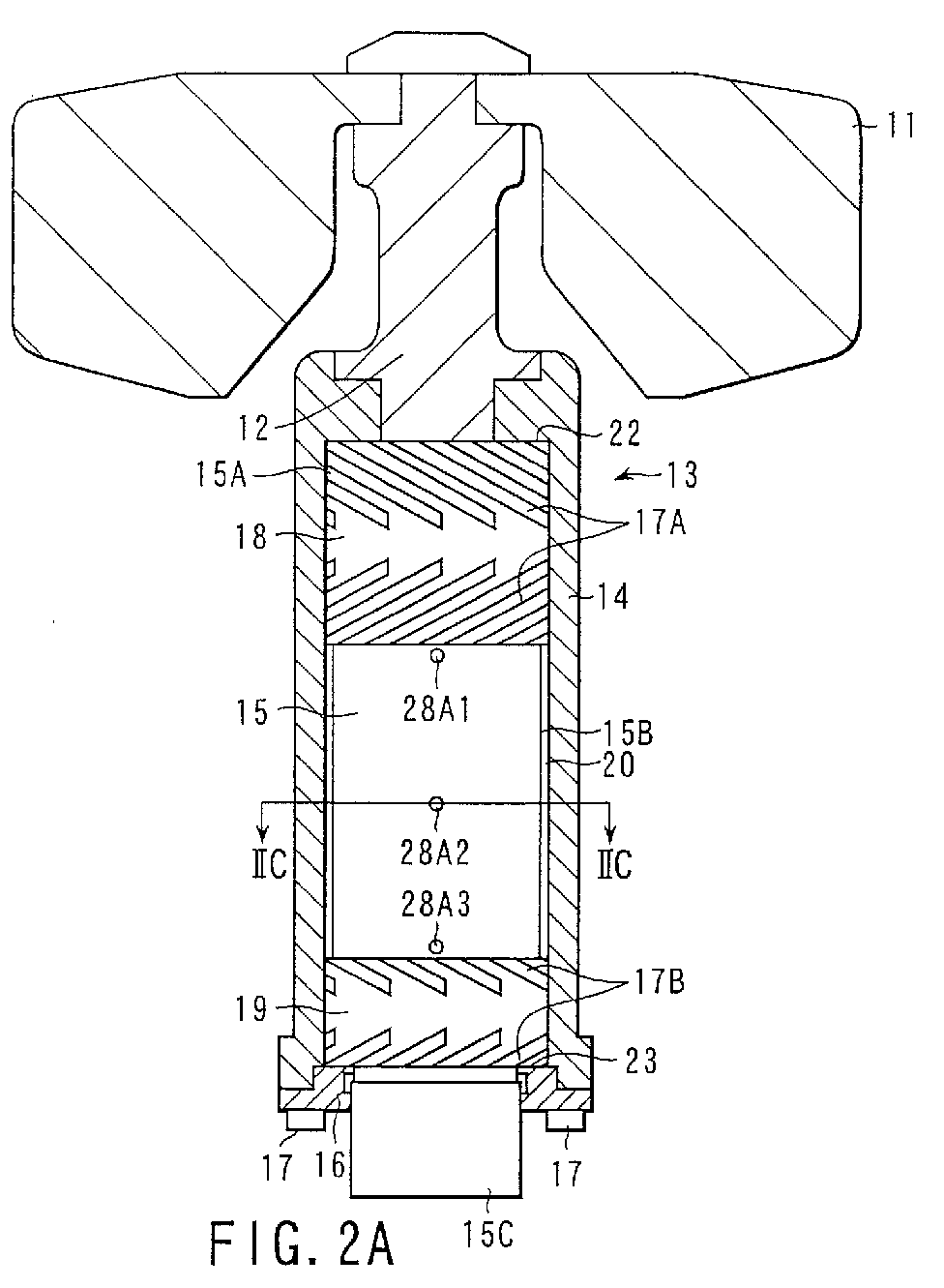
- FIGS. 2A to 2D A rotary-anode-type X-ray tube according to an embodiment of the present invention will now be described with reference to FIGS. 2A to 2D.
- numeral 11 denotes an anode target that emits X-rays as it is irradiated with electron beams from a cathode (not shown).
- the target 11 is coupled to a rotary mechanism 13 by means of a rotating shaft 12.
- the rotary mechanism 13 comprises a rotary structure and a stationary structure.
- the rotary structure is composed of a rotary cylinder 14 in the form of a bottomed cylinder, as shown in FIG. 2A.
- the stationary structure is composed of a substantially columnar stationary shaft 15 that is fitted in the rotary cylinder 14 with a fine gap between the two.
- the bottom opening of the rotary cylinder 14 is sealed by means of a closer 16.
- the closer 16 is fixed to the rotary cylinder 14 by means of screws 17, and along with the cylinder 14, constitutes the rotary structure of the rotary mechanism 13.
- the stationary shaft 15 extends through the closer 16, and its lower end portion 15C forms an anode supporting portion for supporting the anode target 11.
- the rotary mechanism 13 is formed having dynamic-pressure slide bearings between the rotary structure and the stationary structure.
- the stationary shaft 15 has a pair of large-diameter portions 15A on its upper and lower parts, individually, and a small-diameter portion 15B that connects the large-diameter portions 15A.
- Two pairs of herringbone-pattern helical grooves 17A and 17B are formed on the outer peripheral surface of the large-diameter portion 15A.
- An annular space 20 to be filled with a liquid metal is provided between the small-diameter portion 15B and the inner peripheral surface of the rotary cylinder 14.
- a liquid-metal lubricant is fed into the helical grooves 17A and 17B and bearing gaps in which the grooves 17A and 17B face the inner peripheral surface of the rotary cylinder 14.
- the helical grooves and the bearing gaps constitute radial dynamic-pressure slide bearings 18 and 19.
- the liquid-metal lubricant is also stored in the annular space 20 between the small-diameter portion 15B of the stationary shaft 15 and the rotary cylinder 14.
- herringbone-pattern helical grooves 21 are formed in a circle on the upper end face of the stationary shaft 15 and the upper surface of the closer 16, individually.
- the liquid-metal lubricant is fed into the helical grooves 21, a bearing gap in which the upper end face of the stationary shaft 15 and the base of the rotary cylinder 14 face each other, and a bearing gap in which the upper surface of the closer 16 and the lower end face of the stationary shaft 15 face each other.
- the helical grooves and the bearing gaps constitute thrust dynamic-pressure slide bearings 22 and 23.
- a Ga-In-Sn alloy is an example of the liquid-metal lubricant.
- the stationary shaft 15 has three reservoirs 24A to 24C that extend in its axial direction and serve to store the liquid-metal lubricant.
- the reservoirs 24A to 24C are arranged on the circumference of a circle around a tube axis O. As shown in FIG. 2D, the reservoirs extend from the lower end portion 15C and open in the upper end face of the stationary shaft 15. Thus, the three reservoirs 24A to 24C communicate with the thrust dynamic-pressure slide bearing 22.
- the reservoirs 24A to 24C are filled with the liquid-metal lubricant.
- the reservoirs 24A to 24C are provided with first to third groups of ducts 27A1 to 27A3, 27B1 to 27B3, and 27C1 to 27C3, respectively, which are arranged at given spaces in the tube-axis direction.
- the ducts 27A1 to 27A3, 27B1 to 27B3, and 27C1 to 27C3 extend in the radial direction at angular spaces of 120 degrees from one another around the tube axis.
- the first to third groups of ducts 27A1 to 27A3, 27B1 to 27B3, and 27C1 to 27C3 have openings 28A1 to 28A3, 28B1 to 28B3, and 28C1 to 28C3, respectively. All these openings 28A1 to 28A3, 28B1 to 28B3, and 28C1 to 28C3 open in the small-diameter portion 15B of the stationary shaft 15 so that the ducts 27A1 to 27A3, 27B1 to 27B3, and 27C1 to 27C3 communicate with the annular space 20.
- the ducts 27A1 to 27A3, 27B1 to 27B3, and 27C1 to 27C3 and the annular space 20 are also filled with the liquid-metal lubricant.
- the second openings 28B1 to 28B3 are located between the first and third openings 28A1 to 28A3 and 28C1 to 28C3, and the first and third openings 28A1 to 28A3 and 28C1 to 28C3 are located close to the radial dynamic-pressure slide bearings 18 and 19, and open in the small-diameter portion 15B outside bearings 18 and 19.
- the liquid-metal lubricant can be effectively fed from the reservoirs 24A to 24C or the ducts 27A1 to 27A3 and 27C1 to 27C3 to the dynamic-pressure slide bearings 18 and 19 when the rotary cylinder 14 is rotated.
- the lubricant in the bearings 18 and 19 can be prevented from being in short supply.
- the liquid-metal lubricant in the reservoirs 24A to 24C circulates through the ducts 27A1 to 27A3, 27B1 to 27B3, and 27C1 to 27C3, helical grooves, bearing gaps, etc.
- the reservoirs 24A to 24C serve not only as passages through which the lubricant circulates but also as passages through which gases produced in the bearings are circulated.
- the stationary shaft is provided with a plurality of reservoirs, e.g., the three reservoirs 24A to 24C. If one of the reservoirs is clogged with gas pools or the like, thereby preventing the liquid-metal lubricant from being circulated or supplied, therefore, the lubricant can be circulated and supplied to the bearing portions through the two remaining reservoir. Thus, the lubricant can be prevented from being in short supply, so that the rotary structure can rotate steadily with high reliability.
- the respective openings of the ducts 27A1 to 27A3, 27B1 to 27B3, and 27C1 to 27C3 and the helical grooves need not be aligned with one another, so that the manufacture is easy.
- FIGS. 3A to 3D Another embodiment of the present invention will now be described with reference to FIGS. 3A to 3D.
- like numerals refer to corresponding portions, and a repeated description of those portions is partially omitted.
- a stationary shaft 15 is provided with a cooling structure unit 25, as shown in FIGS. 3C and 3D.
- the cooling structure unit 25 extends along the tube axis so as to be surrounded by three reservoirs 24A to 24C. More specifically, as shown in FIG. 3D, a hole is formed extending along the tube axis of the stationary shaft 15, and a heat transfer member with heat conductivity higher than that of the stationary shaft 15 is embedded in the hole and bonded to the inner surface of the hole with wax or the like.
- a lower end 25A of the cooling structure unit 25 projects from an end face of the stationary shaft 15, and partially extends to the outside of a vacuum container (not shown) that constitutes the X-ray tube.
- the heat transfer member that constitutes the cooling structure unit 25 is formed of copper or a composite material that is prepared by infiltrating 35% by weight of copper into a sintered tungsten material.
- the heat dissipation properties of the X-ray tube can be improved by cooling the distal end portion 25A of the cooling structure unit 25 that extends to the outside of the vacuum container, for example.
- the distal end portion 25A of the cooling structure unit 25 that extends to the outside of the vacuum container, for example.
- the cooling structure unit 25 is formed of the heat transfer member.
- the heat transfer member may be replaced with a coolant passage through which insulating oil as a coolant flows.
- the cooling structure unit 25 is a double cylinder that is formed of two sub-cylinders for guiding the coolant. In this case, the coolant introduced through the one sub-cylinder is discharged through the other sub-cylinder. In this arrangement, heat transferred to the stationary shaft 15 is transmitted to the coolant and radiated to the outside. Thus, the temperature of the stationary shaft 15 can be prevented from exceeding a given level.
- reservoirs according to the embodiments described herein are three in number, they may be two to six in number, preferably three or four.
Landscapes
- Engineering & Computer Science (AREA)
- General Engineering & Computer Science (AREA)
- Mechanical Engineering (AREA)
- Physics & Mathematics (AREA)
- Fluid Mechanics (AREA)
- Sliding-Contact Bearings (AREA)
- X-Ray Techniques (AREA)
Abstract
Description
In consequence, the rotation of the rotary structure that constitutes the rotary mechanism becomes unstable. In the worst case, the so-called cling occurs such that a part of the rotary cylinder directly touches a part of the stationary shaft, whereby the rotation of the rotary cylinder is stopped.
a rotary cylinder coupled mechanically to the anode target and having an inner surface inside;
a columnar stationary shaft having a central axis, opposite end faces, a pair of large-diameter portions, and a small-diameter portion between the large-diameter portions, the stationary shaft being fitted in the rotary cylinder, the large- and small-diameter portions having an outer surface each, the outer surface of the small-diameter portion and the inner surface of the rotary cylinder defining an annular first reservoir, the stationary shaft having second reservoirs extending along the central axis therein and a plurality of groups of ducts, wherein each of the second reservoir is connected to the first reservoir by the ducts of the group;
radial dynamic-pressure slide bearings located between the respective outer surfaces of the large-diameter portions and the inner surface of the rotary cylinder, individually;
a thrust dynamic-pressure slide bearing provided between an end face of the stationary shaft and the inner surface of the rotary cylinder; and
a liquid-metal lubricant filling the first and second reservoirs, ducts, and radial and thrust dynamic-pressure slide bearings.
Claims (7)
- A rotary-anode-type X-ray tube characterized by comprising:an anode target (11);a rotary cylinder (14) coupled mechanically to the anode target (11) and having an inner surface inside;a columnar stationary shaft (15) having a central axis, opposite end faces, a pair of large-diameter portions, and a small-diameter portion (15B) between the large-diameter portions (15A), the stationary shaft (15) being fitted in the rotary cylinder (14), the large- and small-diameter portions (15A, 15B) having an outer surface each, the outer surface of the small-diameter portion (15B) and the inner surface of the rotary cylinder (14) defining an annular first reservoir (20), the stationary shaft having second reservoirs (24A to 24C) extending along the central axis therein and a plurality of groups of ducts (27A1 to 27A3, 27B1 to 27B3, 27C1 to 27C3), wherein each of the second reservoir (24A to 24C) is connected to the first reservoir (20) by the ducts of the group (27A1 to 27A3, 27B1 to 27B3, 27C1 to 27C3);radial dynamic-pressure slide bearings (18, 19) located between the respective outer surfaces of the large-diameter portions (15A) and the inner surface of the rotary cylinder (14), individually;a thrust dynamic-pressure slide bearing (22, 23) provided between an end face of the stationary shaft (15) and the inner surface of the rotary cylinder (14); anda liquid-metal lubricant filling the first and second reservoirs (20, 24A~24C), ducts (27A1 to 27A3, 27B1 to 27B3, 27C1 to 27C3), and radial and thrust dynamic-pressure slide bearings (18, 19, 22, 23).
- A rotary-anode-type X-ray tube according to claim 1, characterized in that said second reservoirs (24A to 24C) are located on the same radius around the central axis of the stationary shaft (15).
- A rotary-anode-type X-ray tube according to claim 1, characterized in that said plurality of groups of ducts (27A1 to 27A3, 27B1 to 27B3, 27C1 to 27C3) are arranged at given spaces along the central axis.
- A rotary-anode-type X-ray tube according to claim 1, characterized in that said stationary shaft (15) includes a heat transfer member embedded therein along the central axis thereof and having heat conductivity higher than that of the stationary shaft.
- A rotary-anode-type X-ray tube according to claim 1, characterized in that said stationary shaft (15) has a coolant passage extending along the central axis thereof.
- A rotary-anode-type X-ray tube according to claim 4, characterized in that said second reservoirs (24A to 24C) are located around the heat transfer member.
- A rotary-anode-type X-ray tube according to claim 4, characterized in that said second reservoirs (24A to 24C) are located around the coolant passage.
Applications Claiming Priority (2)
| Application Number | Priority Date | Filing Date | Title |
|---|---|---|---|
| JP2000383881A JP2002184334A (en) | 2000-12-18 | 2000-12-18 | Rotating anode type x-ray tube |
| JP2000383881 | 2000-12-18 |
Publications (3)
| Publication Number | Publication Date |
|---|---|
| EP1215708A2 true EP1215708A2 (en) | 2002-06-19 |
| EP1215708A3 EP1215708A3 (en) | 2004-07-14 |
| EP1215708B1 EP1215708B1 (en) | 2006-09-27 |
Family
ID=18851453
Family Applications (1)
| Application Number | Title | Priority Date | Filing Date |
|---|---|---|---|
| EP01129861A Expired - Lifetime EP1215708B1 (en) | 2000-12-18 | 2001-12-14 | Rotary-anode-type x-ray tube |
Country Status (4)
| Country | Link |
|---|---|
| US (1) | US6477232B2 (en) |
| EP (1) | EP1215708B1 (en) |
| JP (1) | JP2002184334A (en) |
| DE (1) | DE60123367T2 (en) |
Families Citing this family (6)
| Publication number | Priority date | Publication date | Assignee | Title |
|---|---|---|---|---|
| JP4704717B2 (en) * | 2004-09-29 | 2011-06-22 | 勝弘 小野 | Rotating anode type X-ray tube device |
| JP2009081069A (en) * | 2007-09-26 | 2009-04-16 | Toshiba Corp | Rotating anode x-ray tube |
| US20100128848A1 (en) * | 2008-11-21 | 2010-05-27 | General Electric Company | X-ray tube having liquid lubricated bearings and liquid cooled target |
| JP5422311B2 (en) * | 2009-09-08 | 2014-02-19 | 株式会社東芝 | Rotating anode type X-ray tube and rotating anode type X-ray tube device |
| JP6091930B2 (en) * | 2013-03-04 | 2017-03-08 | 東芝電子管デバイス株式会社 | Rotating anode X-ray tube |
| US11017977B1 (en) | 2020-01-24 | 2021-05-25 | GE Precision Healthcare LLC | Liquid metal bearing assembly and method for operating said liquid metal bearing assembly |
Citations (3)
| Publication number | Priority date | Publication date | Assignee | Title |
|---|---|---|---|---|
| EP0552808A1 (en) * | 1992-01-24 | 1993-07-28 | Kabushiki Kaisha Toshiba | Method of manufacturing a rotating anode X-ray tube |
| US5384819A (en) * | 1992-04-08 | 1995-01-24 | Kabushiki Kaisha Toshiba | X-ray tube of the rotary anode type |
| EP1132941A2 (en) * | 2000-03-09 | 2001-09-12 | Kabushiki Kaisha Toshiba | Rotary anode type X-ray tube |
Family Cites Families (4)
| Publication number | Priority date | Publication date | Assignee | Title |
|---|---|---|---|---|
| JP2989085B2 (en) * | 1992-04-08 | 1999-12-13 | 株式会社東芝 | Rotating anode X-ray tube |
| JP3045906B2 (en) * | 1993-11-08 | 2000-05-29 | 株式会社東芝 | Rotating anode X-ray tube |
| JP2966279B2 (en) * | 1994-04-13 | 1999-10-25 | 株式会社東芝 | Method for producing rotary anode type X-ray tube |
| JP3410882B2 (en) * | 1995-11-08 | 2003-05-26 | 株式会社東芝 | Rotating anode X-ray tube |
-
2000
- 2000-12-18 JP JP2000383881A patent/JP2002184334A/en active Pending
-
2001
- 2001-12-07 US US10/005,815 patent/US6477232B2/en not_active Expired - Lifetime
- 2001-12-14 DE DE60123367T patent/DE60123367T2/en not_active Expired - Fee Related
- 2001-12-14 EP EP01129861A patent/EP1215708B1/en not_active Expired - Lifetime
Patent Citations (4)
| Publication number | Priority date | Publication date | Assignee | Title |
|---|---|---|---|---|
| EP0552808A1 (en) * | 1992-01-24 | 1993-07-28 | Kabushiki Kaisha Toshiba | Method of manufacturing a rotating anode X-ray tube |
| US5668849A (en) * | 1992-01-24 | 1997-09-16 | Kabushiki Kaisha Toshiba | Method of manufacturing a rotating anode X-ray tube |
| US5384819A (en) * | 1992-04-08 | 1995-01-24 | Kabushiki Kaisha Toshiba | X-ray tube of the rotary anode type |
| EP1132941A2 (en) * | 2000-03-09 | 2001-09-12 | Kabushiki Kaisha Toshiba | Rotary anode type X-ray tube |
Also Published As
| Publication number | Publication date |
|---|---|
| US6477232B2 (en) | 2002-11-05 |
| US20020075998A1 (en) | 2002-06-20 |
| DE60123367D1 (en) | 2006-11-09 |
| EP1215708B1 (en) | 2006-09-27 |
| EP1215708A3 (en) | 2004-07-14 |
| JP2002184334A (en) | 2002-06-28 |
| DE60123367T2 (en) | 2007-08-02 |
Similar Documents
| Publication | Publication Date | Title |
|---|---|---|
| EP2043129A2 (en) | Rotary anode x-ray tube | |
| US6546078B2 (en) | Rotary anode type X-ray tube | |
| EP0479195B1 (en) | Rotary-anode type x-ray tube | |
| KR940009194B1 (en) | Ratary-anode type x-ray tube | |
| US11017976B2 (en) | Spiral groove bearing assembly with minimized deflection | |
| EP1215708B1 (en) | Rotary-anode-type x-ray tube | |
| US5384819A (en) | X-ray tube of the rotary anode type | |
| US6751291B2 (en) | Rotary anode type X-ray tube | |
| JP7134848B2 (en) | Thrust flange for X-ray tubes with internal cooling channels | |
| US20070009095A1 (en) | Bearing mechanism and X-ray tube | |
| CN1070313C (en) | Rotary anode x-ray tube and its producing method | |
| JP3754512B2 (en) | Rotating anode X-ray tube | |
| JP3724926B2 (en) | Rotating anode X-ray tube | |
| JP4421126B2 (en) | Rotating anode X-ray tube | |
| JP2991391B2 (en) | Rotating anode X-ray tube | |
| JPH04196036A (en) | Rotary anode type x-ray tube | |
| JP3720955B2 (en) | Rotating anode X-ray tube | |
| JPH04144046A (en) | Rotating anode type x-ray tube | |
| JP2003217492A (en) | Rotary positive electrode type x-ray tube | |
| JP2005085645A (en) | Rotary positive electrode type x-ray tube device | |
| JP2002175769A (en) | Rotary anode type x-ray tube and its manufacturing method | |
| JP2003051279A (en) | Rotating anode type x-ray tube | |
| JPH05290772A (en) | Rotary anode x-ray tube |
Legal Events
| Date | Code | Title | Description |
|---|---|---|---|
| PUAI | Public reference made under article 153(3) epc to a published international application that has entered the european phase |
Free format text: ORIGINAL CODE: 0009012 |
|
| 17P | Request for examination filed |
Effective date: 20011214 |
|
| AK | Designated contracting states |
Kind code of ref document: A2 Designated state(s): AT BE CH CY DE DK ES FI FR GB GR IE IT LI LU MC NL PT SE TR |
|
| AX | Request for extension of the european patent |
Free format text: AL;LT;LV;MK;RO;SI |
|
| PUAL | Search report despatched |
Free format text: ORIGINAL CODE: 0009013 |
|
| AK | Designated contracting states |
Kind code of ref document: A3 Designated state(s): AT BE CH CY DE DK ES FI FR GB GR IE IT LI LU MC NL PT SE TR |
|
| AX | Request for extension of the european patent |
Extension state: AL LT LV MK RO SI |
|
| AKX | Designation fees paid |
Designated state(s): DE FR GB |
|
| GRAP | Despatch of communication of intention to grant a patent |
Free format text: ORIGINAL CODE: EPIDOSNIGR1 |
|
| GRAS | Grant fee paid |
Free format text: ORIGINAL CODE: EPIDOSNIGR3 |
|
| GRAA | (expected) grant |
Free format text: ORIGINAL CODE: 0009210 |
|
| AK | Designated contracting states |
Kind code of ref document: B1 Designated state(s): DE FR GB |
|
| REG | Reference to a national code |
Ref country code: GB Ref legal event code: FG4D |
|
| REF | Corresponds to: |
Ref document number: 60123367 Country of ref document: DE Date of ref document: 20061109 Kind code of ref document: P |
|
| ET | Fr: translation filed | ||
| PLBE | No opposition filed within time limit |
Free format text: ORIGINAL CODE: 0009261 |
|
| STAA | Information on the status of an ep patent application or granted ep patent |
Free format text: STATUS: NO OPPOSITION FILED WITHIN TIME LIMIT |
|
| 26N | No opposition filed |
Effective date: 20070628 |
|
| PGFP | Annual fee paid to national office [announced via postgrant information from national office to epo] |
Ref country code: FR Payment date: 20081212 Year of fee payment: 8 |
|
| PGFP | Annual fee paid to national office [announced via postgrant information from national office to epo] |
Ref country code: DE Payment date: 20081211 Year of fee payment: 8 |
|
| PGFP | Annual fee paid to national office [announced via postgrant information from national office to epo] |
Ref country code: GB Payment date: 20081210 Year of fee payment: 8 |
|
| GBPC | Gb: european patent ceased through non-payment of renewal fee |
Effective date: 20091214 |
|
| REG | Reference to a national code |
Ref country code: FR Ref legal event code: ST Effective date: 20100831 |
|
| PG25 | Lapsed in a contracting state [announced via postgrant information from national office to epo] |
Ref country code: FR Free format text: LAPSE BECAUSE OF NON-PAYMENT OF DUE FEES Effective date: 20091231 |
|
| PG25 | Lapsed in a contracting state [announced via postgrant information from national office to epo] |
Ref country code: DE Free format text: LAPSE BECAUSE OF NON-PAYMENT OF DUE FEES Effective date: 20100701 |
|
| PG25 | Lapsed in a contracting state [announced via postgrant information from national office to epo] |
Ref country code: GB Free format text: LAPSE BECAUSE OF NON-PAYMENT OF DUE FEES Effective date: 20091214 |