TECHNICAL FIELD
The present disclosure relates to exhaust sensors, and particularly
to a method for disposing electrodes on a ceramic in an exhaust sensor.
BACKGROUND
Oxygen sensors are used in a variety of applications that require
qualitative and quantitative analysis of gases. In automotive applications, the
direct relationship between oxygen concentration in the exhaust gas and air to
fuel ratio (A/F) of the fuel mixture supplied to the engine allows the oxygen
sensor to provide oxygen concentration measurements for determination of
optimum combustion conditions, maximization of fuel economy, and
management of exhaust emissions.
Future emissions requirements will require automobiles to have
lower emissions. As a result, future oxygen sensors will need to have faster lag
and response times while maintaining durability so that emissions can be
reduced during the "cold" portion of the emissions test. Current sensors are
designed such that they typically perform most efficiently at elevated
temperatures around 600°C. Therefore, while the engine and exhaust system are
warming up from a cold start, the sensors do not allow the engine to run at
optimum combustion conditions. As a result, emissions at low temperatures can
be higher as compared to emissions at the normal operating temperature of the
engine. The advanced emissions systems of the future will also require sensors
to perform with less variability at normal operating conditions. The addition of
heaters in the sensors have reduced the variability, especially at lower
temperatures, but additional advances are needed.
A conventional oxygen sensor consists of an ionically conductive
solid electrolyte, a sensing electrode on the sensor's exterior, which is exposed
to the exhaust gases, a porous protective layer disposed over the sensing
electrode, and a reference electrode on the sensor's interior surface exposed to a
known oxygen partial pressure. Sensors typically used in automotive
applications use a yttria stabilized, zirconia based electrochemical galvanic cell
with porous platinum electrodes operating in potentiometric mode to detect the
relative amounts of oxygen present in an automobile engine's exhaust. Such
sensors indicate qualitatively whether the engine is operating in fuel rich or fuel
lean conditions, without quantifying the actual air to fuel ratio of the exhaust
mixture.
The performance of the sensor can be influenced by the treatment
of the sensor's components during the manufacturing process. During the
manufacturing process of a typical electrolyte of a sensor, the stabilized zirconia
is sintered, either with a liquid phase present or through solid state methods.
Due to impurities, e.g., silica, present in the typical starting zirconia powder,
these processes can create a surface that is rich in silica. The presence of the
silica is an impedance to oxygen diffusion from the platinum electrode to the
zirconia electrolyte, thereby impeding the performance of the sensor.
Solid state sintering is a method that can be used to minimize
contamination of the electrodes with impurities coming from the solid
electrolyte when co-firing the electrodes. This necessarily requires high
temperatures in excess of 1,500°C. However, such high temperatures can over
sinter the electrode and cause a loss in low temperature catalytic activity. As a
result, a higher wattage heater is needed to compensate for the deficiencies in
electrode catalytic activity and interfacial impedance between the platinum
electrode and stabilized zirconia electrolyte in order to obtain acceptable
performance at lower exhaust temperatures.
Accordingly, there remains a pressing need in the art for
improved sensors that can respond to changes in the air to fuel ratio more
quickly and perform adequately at low temperatures without the use of
increased wattage heater(s).
SUMMARY
The deficiencies of the above-discussed prior art are overcome or
alleviated by the gas sensor and method of producing the same. The sensor
comprises an electrolyte disposed between a sensing electrode and a reference
electrode, with a protective layer contacting the sensing electrode. At least one
of said sensing electrode and said reference electrode has a porosity of about
15% or greater.
The method for manufacturing the sensor comprises employing a
slip. The slip is applied to the electrolyte to form the electrodes, and the
electrolyte is heated to a temperature of less than about 1,500°C.
BRIEF DESCRIPTION OF THE DRAWINGS
The gas sensor will now be described, by way of example only,
with reference to the accompanying drawing, which is meant to be exemplary,
not limiting.
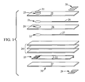
The Figure is an expanded view of one embodiment of an oxygen
sensor.
DETAILED DESCRIPTION
Although described in connection with an oxygen sensor, it is to
be understood that the sensor could be a nitrogen oxide sensor, hydrogen sensor,
hydrocarbon sensor, or the like, having any known geometry (e.g., planar,
conical, or the like). Additionally, the electrode could be employed in a spark
plug as well as in a sensor. Furthermore, while oxygen is the reference gas used
in the description disclosed herein, it should be understood that other gases
could be employed as a reference gas.
The sensor comprises an electrolyte disposed between and in
ionic communication with a sensing electrode capable of sensing an exhaust gas
and a reference electrode capable of sensing a reference gas; an optional
protective layer can be disposed on a side of the sensing electrode opposite the
electrolyte, with an optional a protective coating disposed on the second side of
the protective layer.
In one embodiment, the sensor is configured according to the
Figure. The Figure shows a sensor (30) with an ionically conductive solid
electrolyte (20), a sensing electrode (21) disposed in ionic communication with
the solid electrolyte (20), and a porous protective layer (23) disposed on a side
of the sensing electrode (21) opposite the solid electrolyte (20). On a second
side of the solid electrolyte (20) is a reference electrode (22). The electrolyte
(20) and porous protective layer (23) can be disposed adjacent to or as inserts
within dielectric substrate layers 36, 35, respectively. On a second side of the
reference electrode (22) can be support layers (24, 37), with a heater (25)
disposed therebetween. The reference electrode (22), sensing electrode (21),
and heater (25) are connected to contacts (28, 29) on the outer sides of the
sensor through vias (not shown) with leads (27, 26, 32) respectively.
The substrate layers (35, 36), support layers (24, 37), heater (25),
contacts (28, 29), leads (26, 27, 32), and vias can be composed of materials
conventionally used in exhaust sensors. For example, the substrate layers (35,
36) and support layer(s) (24, 37) can comprise a dielectric material such as a
metal oxide, e.g., alumina, and the like, while the heater(s) (25), leads (26, 27,
32), vias and contacts (28, 29) can comprise an electrically conductive metal
such as platinum, palladium, ruthenium, and the like, and other metals, oxides,
alloys and mixtures comprising at least one of the foregoing metals.
The solid electrolyte (20) can comprise any material
conventionally employed as sensor electrolytes, including, but not limited to,
zirconia which may optionally be stabilized calcium, barium, yttrium,
magnesium, aluminum, lanthanum, cesium, gadolinium, and the like, as well as
oxides, alloys, and combinations comprising at least one of the foregoing
electrolyte materials. The electrolyte can be formed by combining the
electrolyte material with optional sintering aide(s) (e.g., alumina, silica and the
like), stabilizers, and conventional constituents. Preferably, the electrolyte
material, e.g., zirconia, has a purity of about 99.7% or greater, with a purity of
about 99.9% or greater preferred. Furthermore, it is especially preferred that the
silica content of the electrolyte material be below about 0.1%, with a silica
content below about 0.01% even more preferred, based upon the total weight of
electrolyte. Additionally, a particle size of less than about 10 microns is
preferred, with a particle size of less than about 8 microns especially preferred.
The amount of stabilizer employed is based upon the type of
electrolyte material and stabilizer utilized. Typically, for stabilized zirconia, a
sufficient amount of stabilizer is employed to stabilize the zirconia in the
tetragonal phase. Similarly, a sufficient amount of sintering aide is employed to
reduce the sintering temperature while not adversely affecting the electrolytic
properties. Generally up to about 15 mole percent (mole%) stabilizer and up to
about 15 mole% sintering aide, based upon the total weight of the electrolyte,
can be used; with about 1 mole% to about 10 mole% stabilizer preferred and
about 1 mole% to about 12 mole% sintering aide preferred. For example,
zirconia having a particle size of less than about 0.2 to about 8 microns and a
purity of greater than about 99.9% can be co-reacted with up to about 10 mole%
yttria and about 2 mole% to about 12 mole% alumina. The resulting electrolyte
can be sintered at a temperature of less than about 1,500°C, preferably at a
temperature of about 1,480°C or less, and more preferably at a temperature of
about 1,400°C to about 1,450°C.
Disposed on or adjacent to both sides of the electrolyte are
electrodes (21, 22). These electrodes can comprise a catalyst, as well as a
ceramic, fugitive materials, dissolved organometallics, and/or dissolved
organics, and the like. Possible catalysts comprise catalysts conventionally
employed in sensors, such as metals including platinum, palladium, gold,
osmium, rhodium, iridium, silver, ruthenium, zirconium, yttrium, cerium,
calcium, aluminum, and the like, as well as alloys, oxides, and combinations
comprising at least one of the foregoing materials. Preferably, the electrodes
further comprise a ceramic material to enhance hardness and adhesion to the
electrolyte. Generally the electrode can comprise up to about 80 wt% ceramic,
with up to about 60 wt% ceramic more preferred, and about 15 wt% to about 55
wt% ceramic especially preferred, based upon the total weight of the electrodes.
Possible ceramics include metal oxides such as alumina, zirconia, yttria, ceria,
strontia, barium cerium oxide, strontium cerium zirconates, barium cerium
zirconates, lanthana, magnesia, scandia, and the like, and mixtures comprising
at least one of the foregoing metal oxides such as yttria-zirconia, yttria-alumina,
scandia-zirconia, scandia-alumina, yttria-alumina-zirconia, scandia-alumina-zirconia,
and the like.
The electrodes can be disposed on the electrolyte or on the layer
adjacent to the electrolyte, by known methods in the art, including, but not
limited to sputtering, plating, screening, striping, inking, and the like.
Preferably, the electrodes are formed by dipping the electrolyte into a slip
comprising a mixture of metal particles and other additives in a single solvent or
a mixture of solvents. As stated above, in addition to metal particles, the slip
may contain ceramic particles, fugitive materials, dissolved organics, dissolved
organometallics, and the like. Possible fugitive materials, include, but are not
limited to, carbon black, graphite, and/or other non-dissolved organics, as well
as combinations comprising at least one of the foregoing fugitive materials.
Possible dissolved organics, include, but are not limited to, acrylic binders,
polyvinyl alcohol, 1-ethoxypropan-2-ol, turpentine, squeegee medium, 1-methoxy-2-propanol
acetate, butyl acetate, dibutyl phthalate, fatty acids, acrylic
resin, ethyl cellulose, 3-hydroxy,2,2,4-trimethylpentyl isobutyrate, terpineol,
butyl carbitol acetate, cetyl alcohol, cellulose ethylether resin, and the like, as
well as combinations comprising at least one of the foregoing dissolved
organics. Possible dissolved organometallics, include, but are not limited to,
zirconium 2-ethyl hexanoate, yttrium 2-ethylhexanoate, aluminum
methoxyethanol, zirconium neodecanoates, zirconium naphthenates, zirconium
tallates, zirconium carboxylates, yttrium 2-ethyl hexanoate, yttrium
neodecanoates, yttrium naphthenates, yttrium tallates, yttrium carboxylates,
scandium 2-ethyl hexanoate, aluminum isopropoxide, aluminum 2-ethylhexanoate
and aluminum 2-methoxyethanol, and the like, and mixtures
comprising at least one of the foregoing organometallics.
Preferably, the thickness of the electrodes is about 1.0 microns to about
25 microns, with a thickness of about 5 microns to about 20 microns preferred,
and about 10 microns to about 18 microns more preferred. The electrodes can
be fired at a temperature of less than about 1,500°C, preferably at a temperature
of less than about 1,450°C, and more preferably at a temperature of about
1,400°C to about 1,450°C.
Disposed adjacent to the second side of the sensing electrode
(21) is a protective layer (23) comprising a metal oxide alone or in combination
with one or more alkaline earths and/or rare earths. Possible metal oxides
include zirconia, alumina, magnesia, titania, and the like; and mixtures
comprising at least one of the foregoing metal oxides. Possible metals (alkaline
earth and rare earth) comprise barium, calcium, potassium, sodium, lanthanum,
neodymium, gadolinium, cerium, and the like and mixtures comprising at least
one of the foregoing metals. On the outer surface of the protective layer can be
a protective coating (31). The protective coating is preferably a single layer of a
material such as alumina, magnesium aluminate, and the like, as well as
combinations comprising at least one of the foregoing materials.
Example
The following example was used to prepare an exhaust sensor
having a platinum electrode, yttria doped zirconia electrolyte, alumina support
layers, an alumina protective layer, and a protective coating.
A commercially available co-reacted partially stabilized zirconia
(PSZ) powder from SEPR, containing 90.0 mole % zirconia, 5.0 mole % yttria,
5.0 mole % alumina, and 0.05 mole % silica, was milled in a dry ball mill to
reduce the particle size of the alumina portion to an average size of 1 micron (µ)
or smaller. The milled powder was then mixed with organic processing aids,
including a binder, in an aqueous blend under high shear to eliminate any
agglomeration. The mixture was attrition milled to further de-agglomerate the
particles. The batch was spray dried to uniformly disperse the binder, then
isostatically molded and ground to the desired shape of the electrolyte. The
electrolyte was then masked on one edge and dipped in a slip comprising 14
wt% platinum, 3.4 wt% yttria-zirconia, 1.4 wt% butylacetate, 4.0 wt% dibutyl
phthalate, 2.9 wt% ethyl cellulose, 8.0 wt% terpineol, 0.6 wt% butyl carbitol
acetate, and 65.7 wt% ethanol, to form separate electrodes, one on each side of
the electrolyte, with thicknesses of about 8.4 microns. The element was then
fired at 1,450°C to densify the solid electrolyte and form the active electrode
having a thickness of about 5.2 microns and a composition of 78 wt% platinum
and 22 wt% yttria-zirconia (comprising of 12 mole% yttria). The part was
coated with a plasma sprayed magnesium aluminate to form a protective
coating, and then coated with an alumina coating to provide poison resistance.
The sensor was treated under nitrogen at 800°C to condition the sensor and
reduce the green effect.
A sensor prepared as described above, i.e., with dipped
electrodes, was tested along with sensors prepared with sputtered electrodes and
plated electrodes. Results of the tests are listed in Tables I and II. Table I lists
the data from tests conducted at 0.5 Hertz (Hz) at 260°C, with a 12 Watt (W)
heater. Table II lists the data from tests conducted at 2 Hz at 595°C.
As can be seen from both Table I and Table II, although Sample
6 possessed a lower Vmax (i.e., maximum voltage derived by catalytic
oxidation on the outer sensing electrode) than some other samples, it possessed
the rich to lean (RL) versus lowest lean to rich (LR) response time ratio
(RL/LR). Typically RL/LRs of less than about 5.0 are required (e.g., if a ratio of
5 or greater is received, a check engine signal is given indicating a sensor is
faulty). It is preferred that the faulty sensor signal be triggered at a RL/LR of
about 3. Consequently, the sensor should have a ratio well below about 3.0 to
ensure a sensor life of at least about 50,000 miles, with up to and exceeding
about 100,000 miles preferred. As a result, a RL/LR of about 1.5 or less is
preferred at low temperatures (e.g., about 260°C), with about 1.0 or less more
preferred, and about 0.75 or less especially preferred. Additionally, an RL/LR
of about 1.25 or less, with about 1.0 or less preferred at high temperatures (e.g.,
about 595°C).
| | Method | Vmin (mV) | Vmax (mV) | LR time (ms) | RL time (ms) | RL/LR ratio | Resist. (ohms) |
| 1 | sputtered outer striped inner | 75 | 861 | 29 | 74 | 2.6 | 2768 |
| 2 | plated outer plated inner | 104 | 842 | 69 | 127 | 1.8 | 2680 |
| 3 | sputtered outer dipped inner | 88 | 872 | 23 | 85 | 3.7 | 2475 |
| 4 | dipped outer striped inner | 79 | 813 | 36 | 69 | 1.9 | 2640 |
| 5 | dipped outer dipped inner | 84 | 807 | 32 | 58 | 1.8 | 1870 |
| 6 | dipped outer dipped inner (yttria rich) | 75 | 785 | 74 | 42 | 0.6 | 1610 |
| | Method | Vmin (mV) | Vmax (mV) | LR time (ms) | RL time (ms) | RL/LR ratio |
| 1 | sputtered outer striped inner | 86 | 789 | 27 | 41 | 1.5 |
| 2 | plated outer plated inner | 165 | 823 | 39 | 91 | 2.3 |
| 3 | sputtered outer dipped inner | 113 | 794 | 14 | 35 | 2.5 |
| 4 | dipped outer striped inner | 91 | 786 | 21 | 38 | 1.8 |
| 5 | dipped outer dipped inner | 107 | 807 | 14 | 28 | 2.0 |
| 6 | dipped outer dipped inner (yttria rich) | 96 | 763 | 29 | 28 | 1.0 |
| 2 Hz at 595°C, 0.3 A/F |
This conical sensor comprises an electrolyte having a lower impedance (e.g.,
below about 2,000 ohms, wherein conventional conical sensors have an
impedance of greater than 2,400 ohms), flat plat and wide range have much
higher purity and therefore much lower resistance. In particular the wide range
sensor must be below 100 ohms, preferably below 40 ohms and most preferred
below 30 ohms and a lower firing temperature that minimizes de-activation of
the electrode. The electrolyte firing temperature is preferably about 1,430°C to
about 1,480°C, wherein conventional zirconia electrolyte firing temperatures are
about 1,500°C. This is particularly relevant when forming a co-fired sensor
where the electrode can over-sinter at temperatures exceeding about 1,475°C.
Since the electrolyte preferably comprises a co-reacted zirconia, yttria, alumina
body, in addition to the sintering temperature being reduced, the silica content
being about 0.05 mole% or less, with about 0.005 mole % or less preferred, and
therefore the impedance is reduced.
Unlike conventional electrodes, slip formed electrodes have
substantially increased porosity, e.g., about 15% or greater, with about 20% or
greater preferred, about 25% or greater more preferred, and about 30% to about
50% most preferred. In contrast, plated electrodes comprise a porosity up to
about 2%, sputtered electrodes have a porosity of about 5% or less, and screen
printed sensors have a porosity of up to about 10%, with about 6% to 7%
common. Additionally, the slip formed electrodes possess a virtually
instantaneous switching while conventional sensors can experience a switching
time of 200 milliseconds (ms).
While preferred embodiments have been shown and described,
various modifications and substitutions may be made thereto without departing
from the spirit and scope of the invention. Accordingly, it is to be understood
that the present invention has been described by way of illustration and not
limitation.