EP1215183B1 - Ceramic matrix composite parts with channels and process of making the same - Google Patents
Ceramic matrix composite parts with channels and process of making the same Download PDFInfo
- Publication number
- EP1215183B1 EP1215183B1 EP01310556A EP01310556A EP1215183B1 EP 1215183 B1 EP1215183 B1 EP 1215183B1 EP 01310556 A EP01310556 A EP 01310556A EP 01310556 A EP01310556 A EP 01310556A EP 1215183 B1 EP1215183 B1 EP 1215183B1
- Authority
- EP
- European Patent Office
- Prior art keywords
- process according
- channels
- fibers
- ceramic matrix
- inch
- Prior art date
- Legal status (The legal status is an assumption and is not a legal conclusion. Google has not performed a legal analysis and makes no representation as to the accuracy of the status listed.)
- Expired - Lifetime
Links
Images


Classifications
-
- B—PERFORMING OPERATIONS; TRANSPORTING
- B32—LAYERED PRODUCTS
- B32B—LAYERED PRODUCTS, i.e. PRODUCTS BUILT-UP OF STRATA OF FLAT OR NON-FLAT, e.g. CELLULAR OR HONEYCOMB, FORM
- B32B18/00—Layered products essentially comprising ceramics, e.g. refractory products
-
- C—CHEMISTRY; METALLURGY
- C04—CEMENTS; CONCRETE; ARTIFICIAL STONE; CERAMICS; REFRACTORIES
- C04B—LIME, MAGNESIA; SLAG; CEMENTS; COMPOSITIONS THEREOF, e.g. MORTARS, CONCRETE OR LIKE BUILDING MATERIALS; ARTIFICIAL STONE; CERAMICS; REFRACTORIES; TREATMENT OF NATURAL STONE
- C04B35/00—Shaped ceramic products characterised by their composition; Ceramics compositions; Processing powders of inorganic compounds preparatory to the manufacturing of ceramic products
- C04B35/515—Shaped ceramic products characterised by their composition; Ceramics compositions; Processing powders of inorganic compounds preparatory to the manufacturing of ceramic products based on non-oxide ceramics
- C04B35/56—Shaped ceramic products characterised by their composition; Ceramics compositions; Processing powders of inorganic compounds preparatory to the manufacturing of ceramic products based on non-oxide ceramics based on carbides or oxycarbides
- C04B35/565—Shaped ceramic products characterised by their composition; Ceramics compositions; Processing powders of inorganic compounds preparatory to the manufacturing of ceramic products based on non-oxide ceramics based on carbides or oxycarbides based on silicon carbide
- C04B35/573—Shaped ceramic products characterised by their composition; Ceramics compositions; Processing powders of inorganic compounds preparatory to the manufacturing of ceramic products based on non-oxide ceramics based on carbides or oxycarbides based on silicon carbide obtained by reaction sintering or recrystallisation
-
- C—CHEMISTRY; METALLURGY
- C04—CEMENTS; CONCRETE; ARTIFICIAL STONE; CERAMICS; REFRACTORIES
- C04B—LIME, MAGNESIA; SLAG; CEMENTS; COMPOSITIONS THEREOF, e.g. MORTARS, CONCRETE OR LIKE BUILDING MATERIALS; ARTIFICIAL STONE; CERAMICS; REFRACTORIES; TREATMENT OF NATURAL STONE
- C04B35/00—Shaped ceramic products characterised by their composition; Ceramics compositions; Processing powders of inorganic compounds preparatory to the manufacturing of ceramic products
- C04B35/622—Forming processes; Processing powders of inorganic compounds preparatory to the manufacturing of ceramic products
- C04B35/626—Preparing or treating the powders individually or as batches ; preparing or treating macroscopic reinforcing agents for ceramic products, e.g. fibres; mechanical aspects section B
- C04B35/628—Coating the powders or the macroscopic reinforcing agents
- C04B35/62844—Coating fibres
- C04B35/62857—Coating fibres with non-oxide ceramics
- C04B35/62865—Nitrides
- C04B35/62868—Boron nitride
-
- C—CHEMISTRY; METALLURGY
- C04—CEMENTS; CONCRETE; ARTIFICIAL STONE; CERAMICS; REFRACTORIES
- C04B—LIME, MAGNESIA; SLAG; CEMENTS; COMPOSITIONS THEREOF, e.g. MORTARS, CONCRETE OR LIKE BUILDING MATERIALS; ARTIFICIAL STONE; CERAMICS; REFRACTORIES; TREATMENT OF NATURAL STONE
- C04B35/00—Shaped ceramic products characterised by their composition; Ceramics compositions; Processing powders of inorganic compounds preparatory to the manufacturing of ceramic products
- C04B35/71—Ceramic products containing macroscopic reinforcing agents
- C04B35/78—Ceramic products containing macroscopic reinforcing agents containing non-metallic materials
- C04B35/80—Fibres, filaments, whiskers, platelets, or the like
-
- F—MECHANICAL ENGINEERING; LIGHTING; HEATING; WEAPONS; BLASTING
- F01—MACHINES OR ENGINES IN GENERAL; ENGINE PLANTS IN GENERAL; STEAM ENGINES
- F01D—NON-POSITIVE DISPLACEMENT MACHINES OR ENGINES, e.g. STEAM TURBINES
- F01D5/00—Blades; Blade-carrying members; Heating, heat-insulating, cooling or antivibration means on the blades or the members
- F01D5/12—Blades
- F01D5/14—Form or construction
- F01D5/18—Hollow blades, i.e. blades with cooling or heating channels or cavities; Heating, heat-insulating or cooling means on blades
- F01D5/186—Film cooling
-
- F—MECHANICAL ENGINEERING; LIGHTING; HEATING; WEAPONS; BLASTING
- F23—COMBUSTION APPARATUS; COMBUSTION PROCESSES
- F23R—GENERATING COMBUSTION PRODUCTS OF HIGH PRESSURE OR HIGH VELOCITY, e.g. GAS-TURBINE COMBUSTION CHAMBERS
- F23R3/00—Continuous combustion chambers using liquid or gaseous fuel
- F23R3/007—Continuous combustion chambers using liquid or gaseous fuel constructed mainly of ceramic components
-
- B—PERFORMING OPERATIONS; TRANSPORTING
- B29—WORKING OF PLASTICS; WORKING OF SUBSTANCES IN A PLASTIC STATE IN GENERAL
- B29B—PREPARATION OR PRETREATMENT OF THE MATERIAL TO BE SHAPED; MAKING GRANULES OR PREFORMS; RECOVERY OF PLASTICS OR OTHER CONSTITUENTS OF WASTE MATERIAL CONTAINING PLASTICS
- B29B11/00—Making preforms
- B29B11/14—Making preforms characterised by structure or composition
- B29B11/16—Making preforms characterised by structure or composition comprising fillers or reinforcement
-
- C—CHEMISTRY; METALLURGY
- C04—CEMENTS; CONCRETE; ARTIFICIAL STONE; CERAMICS; REFRACTORIES
- C04B—LIME, MAGNESIA; SLAG; CEMENTS; COMPOSITIONS THEREOF, e.g. MORTARS, CONCRETE OR LIKE BUILDING MATERIALS; ARTIFICIAL STONE; CERAMICS; REFRACTORIES; TREATMENT OF NATURAL STONE
- C04B2235/00—Aspects relating to ceramic starting mixtures or sintered ceramic products
- C04B2235/02—Composition of constituents of the starting material or of secondary phases of the final product
- C04B2235/30—Constituents and secondary phases not being of a fibrous nature
- C04B2235/38—Non-oxide ceramic constituents or additives
- C04B2235/3817—Carbides
- C04B2235/3826—Silicon carbides
-
- C—CHEMISTRY; METALLURGY
- C04—CEMENTS; CONCRETE; ARTIFICIAL STONE; CERAMICS; REFRACTORIES
- C04B—LIME, MAGNESIA; SLAG; CEMENTS; COMPOSITIONS THEREOF, e.g. MORTARS, CONCRETE OR LIKE BUILDING MATERIALS; ARTIFICIAL STONE; CERAMICS; REFRACTORIES; TREATMENT OF NATURAL STONE
- C04B2235/00—Aspects relating to ceramic starting mixtures or sintered ceramic products
- C04B2235/02—Composition of constituents of the starting material or of secondary phases of the final product
- C04B2235/50—Constituents or additives of the starting mixture chosen for their shape or used because of their shape or their physical appearance
- C04B2235/52—Constituents or additives characterised by their shapes
- C04B2235/5208—Fibers
- C04B2235/5216—Inorganic
- C04B2235/524—Non-oxidic, e.g. borides, carbides, silicides or nitrides
- C04B2235/5244—Silicon carbide
-
- C—CHEMISTRY; METALLURGY
- C04—CEMENTS; CONCRETE; ARTIFICIAL STONE; CERAMICS; REFRACTORIES
- C04B—LIME, MAGNESIA; SLAG; CEMENTS; COMPOSITIONS THEREOF, e.g. MORTARS, CONCRETE OR LIKE BUILDING MATERIALS; ARTIFICIAL STONE; CERAMICS; REFRACTORIES; TREATMENT OF NATURAL STONE
- C04B2235/00—Aspects relating to ceramic starting mixtures or sintered ceramic products
- C04B2235/02—Composition of constituents of the starting material or of secondary phases of the final product
- C04B2235/50—Constituents or additives of the starting mixture chosen for their shape or used because of their shape or their physical appearance
- C04B2235/52—Constituents or additives characterised by their shapes
- C04B2235/5208—Fibers
- C04B2235/5252—Fibers having a specific pre-form
-
- C—CHEMISTRY; METALLURGY
- C04—CEMENTS; CONCRETE; ARTIFICIAL STONE; CERAMICS; REFRACTORIES
- C04B—LIME, MAGNESIA; SLAG; CEMENTS; COMPOSITIONS THEREOF, e.g. MORTARS, CONCRETE OR LIKE BUILDING MATERIALS; ARTIFICIAL STONE; CERAMICS; REFRACTORIES; TREATMENT OF NATURAL STONE
- C04B2235/00—Aspects relating to ceramic starting mixtures or sintered ceramic products
- C04B2235/02—Composition of constituents of the starting material or of secondary phases of the final product
- C04B2235/50—Constituents or additives of the starting mixture chosen for their shape or used because of their shape or their physical appearance
- C04B2235/52—Constituents or additives characterised by their shapes
- C04B2235/5208—Fibers
- C04B2235/5264—Fibers characterised by the diameter of the fibers
-
- C—CHEMISTRY; METALLURGY
- C04—CEMENTS; CONCRETE; ARTIFICIAL STONE; CERAMICS; REFRACTORIES
- C04B—LIME, MAGNESIA; SLAG; CEMENTS; COMPOSITIONS THEREOF, e.g. MORTARS, CONCRETE OR LIKE BUILDING MATERIALS; ARTIFICIAL STONE; CERAMICS; REFRACTORIES; TREATMENT OF NATURAL STONE
- C04B2235/00—Aspects relating to ceramic starting mixtures or sintered ceramic products
- C04B2235/02—Composition of constituents of the starting material or of secondary phases of the final product
- C04B2235/50—Constituents or additives of the starting mixture chosen for their shape or used because of their shape or their physical appearance
- C04B2235/52—Constituents or additives characterised by their shapes
- C04B2235/5208—Fibers
- C04B2235/5268—Orientation of the fibers
-
- C—CHEMISTRY; METALLURGY
- C04—CEMENTS; CONCRETE; ARTIFICIAL STONE; CERAMICS; REFRACTORIES
- C04B—LIME, MAGNESIA; SLAG; CEMENTS; COMPOSITIONS THEREOF, e.g. MORTARS, CONCRETE OR LIKE BUILDING MATERIALS; ARTIFICIAL STONE; CERAMICS; REFRACTORIES; TREATMENT OF NATURAL STONE
- C04B2235/00—Aspects relating to ceramic starting mixtures or sintered ceramic products
- C04B2235/60—Aspects relating to the preparation, properties or mechanical treatment of green bodies or pre-forms
- C04B2235/602—Making the green bodies or pre-forms by moulding
- C04B2235/6028—Shaping around a core which is removed later
-
- C—CHEMISTRY; METALLURGY
- C04—CEMENTS; CONCRETE; ARTIFICIAL STONE; CERAMICS; REFRACTORIES
- C04B—LIME, MAGNESIA; SLAG; CEMENTS; COMPOSITIONS THEREOF, e.g. MORTARS, CONCRETE OR LIKE BUILDING MATERIALS; ARTIFICIAL STONE; CERAMICS; REFRACTORIES; TREATMENT OF NATURAL STONE
- C04B2235/00—Aspects relating to ceramic starting mixtures or sintered ceramic products
- C04B2235/60—Aspects relating to the preparation, properties or mechanical treatment of green bodies or pre-forms
- C04B2235/614—Gas infiltration of green bodies or pre-forms
-
- C—CHEMISTRY; METALLURGY
- C04—CEMENTS; CONCRETE; ARTIFICIAL STONE; CERAMICS; REFRACTORIES
- C04B—LIME, MAGNESIA; SLAG; CEMENTS; COMPOSITIONS THEREOF, e.g. MORTARS, CONCRETE OR LIKE BUILDING MATERIALS; ARTIFICIAL STONE; CERAMICS; REFRACTORIES; TREATMENT OF NATURAL STONE
- C04B2235/00—Aspects relating to ceramic starting mixtures or sintered ceramic products
- C04B2235/60—Aspects relating to the preparation, properties or mechanical treatment of green bodies or pre-forms
- C04B2235/616—Liquid infiltration of green bodies or pre-forms
-
- C—CHEMISTRY; METALLURGY
- C04—CEMENTS; CONCRETE; ARTIFICIAL STONE; CERAMICS; REFRACTORIES
- C04B—LIME, MAGNESIA; SLAG; CEMENTS; COMPOSITIONS THEREOF, e.g. MORTARS, CONCRETE OR LIKE BUILDING MATERIALS; ARTIFICIAL STONE; CERAMICS; REFRACTORIES; TREATMENT OF NATURAL STONE
- C04B2235/00—Aspects relating to ceramic starting mixtures or sintered ceramic products
- C04B2235/65—Aspects relating to heat treatments of ceramic bodies such as green ceramics or pre-sintered ceramics, e.g. burning, sintering or melting processes
- C04B2235/66—Specific sintering techniques, e.g. centrifugal sintering
- C04B2235/661—Multi-step sintering
- C04B2235/662—Annealing after sintering
- C04B2235/663—Oxidative annealing
-
- C—CHEMISTRY; METALLURGY
- C04—CEMENTS; CONCRETE; ARTIFICIAL STONE; CERAMICS; REFRACTORIES
- C04B—LIME, MAGNESIA; SLAG; CEMENTS; COMPOSITIONS THEREOF, e.g. MORTARS, CONCRETE OR LIKE BUILDING MATERIALS; ARTIFICIAL STONE; CERAMICS; REFRACTORIES; TREATMENT OF NATURAL STONE
- C04B2237/00—Aspects relating to ceramic laminates or to joining of ceramic articles with other articles by heating
- C04B2237/30—Composition of layers of ceramic laminates or of ceramic or metallic articles to be joined by heating, e.g. Si substrates
- C04B2237/32—Ceramic
- C04B2237/36—Non-oxidic
- C04B2237/365—Silicon carbide
-
- C—CHEMISTRY; METALLURGY
- C04—CEMENTS; CONCRETE; ARTIFICIAL STONE; CERAMICS; REFRACTORIES
- C04B—LIME, MAGNESIA; SLAG; CEMENTS; COMPOSITIONS THEREOF, e.g. MORTARS, CONCRETE OR LIKE BUILDING MATERIALS; ARTIFICIAL STONE; CERAMICS; REFRACTORIES; TREATMENT OF NATURAL STONE
- C04B2237/00—Aspects relating to ceramic laminates or to joining of ceramic articles with other articles by heating
- C04B2237/30—Composition of layers of ceramic laminates or of ceramic or metallic articles to be joined by heating, e.g. Si substrates
- C04B2237/32—Ceramic
- C04B2237/38—Fiber or whisker reinforced
-
- F—MECHANICAL ENGINEERING; LIGHTING; HEATING; WEAPONS; BLASTING
- F23—COMBUSTION APPARATUS; COMBUSTION PROCESSES
- F23M—CASINGS, LININGS, WALLS OR DOORS SPECIALLY ADAPTED FOR COMBUSTION CHAMBERS, e.g. FIREBRIDGES; DEVICES FOR DEFLECTING AIR, FLAMES OR COMBUSTION PRODUCTS IN COMBUSTION CHAMBERS; SAFETY ARRANGEMENTS SPECIALLY ADAPTED FOR COMBUSTION APPARATUS; DETAILS OF COMBUSTION CHAMBERS, NOT OTHERWISE PROVIDED FOR
- F23M2900/00—Special features of, or arrangements for combustion chambers
- F23M2900/05004—Special materials for walls or lining
-
- F—MECHANICAL ENGINEERING; LIGHTING; HEATING; WEAPONS; BLASTING
- F23—COMBUSTION APPARATUS; COMBUSTION PROCESSES
- F23R—GENERATING COMBUSTION PRODUCTS OF HIGH PRESSURE OR HIGH VELOCITY, e.g. GAS-TURBINE COMBUSTION CHAMBERS
- F23R2900/00—Special features of, or arrangements for continuous combustion chambers; Combustion processes therefor
- F23R2900/03041—Effusion cooled combustion chamber walls or domes
-
- F—MECHANICAL ENGINEERING; LIGHTING; HEATING; WEAPONS; BLASTING
- F23—COMBUSTION APPARATUS; COMBUSTION PROCESSES
- F23R—GENERATING COMBUSTION PRODUCTS OF HIGH PRESSURE OR HIGH VELOCITY, e.g. GAS-TURBINE COMBUSTION CHAMBERS
- F23R2900/00—Special features of, or arrangements for continuous combustion chambers; Combustion processes therefor
- F23R2900/03042—Film cooled combustion chamber walls or domes
-
- Y—GENERAL TAGGING OF NEW TECHNOLOGICAL DEVELOPMENTS; GENERAL TAGGING OF CROSS-SECTIONAL TECHNOLOGIES SPANNING OVER SEVERAL SECTIONS OF THE IPC; TECHNICAL SUBJECTS COVERED BY FORMER USPC CROSS-REFERENCE ART COLLECTIONS [XRACs] AND DIGESTS
- Y10—TECHNICAL SUBJECTS COVERED BY FORMER USPC
- Y10T—TECHNICAL SUBJECTS COVERED BY FORMER US CLASSIFICATION
- Y10T428/00—Stock material or miscellaneous articles
- Y10T428/249921—Web or sheet containing structurally defined element or component
- Y10T428/249953—Composite having voids in a component [e.g., porous, cellular, etc.]
- Y10T428/249967—Inorganic matrix in void-containing component
- Y10T428/249969—Of silicon-containing material [e.g., glass, etc.]
-
- Y—GENERAL TAGGING OF NEW TECHNOLOGICAL DEVELOPMENTS; GENERAL TAGGING OF CROSS-SECTIONAL TECHNOLOGIES SPANNING OVER SEVERAL SECTIONS OF THE IPC; TECHNICAL SUBJECTS COVERED BY FORMER USPC CROSS-REFERENCE ART COLLECTIONS [XRACs] AND DIGESTS
- Y10—TECHNICAL SUBJECTS COVERED BY FORMER USPC
- Y10T—TECHNICAL SUBJECTS COVERED BY FORMER US CLASSIFICATION
- Y10T428/00—Stock material or miscellaneous articles
- Y10T428/249921—Web or sheet containing structurally defined element or component
- Y10T428/249953—Composite having voids in a component [e.g., porous, cellular, etc.]
- Y10T428/249976—Voids specified as closed
-
- Y—GENERAL TAGGING OF NEW TECHNOLOGICAL DEVELOPMENTS; GENERAL TAGGING OF CROSS-SECTIONAL TECHNOLOGIES SPANNING OVER SEVERAL SECTIONS OF THE IPC; TECHNICAL SUBJECTS COVERED BY FORMER USPC CROSS-REFERENCE ART COLLECTIONS [XRACs] AND DIGESTS
- Y10—TECHNICAL SUBJECTS COVERED BY FORMER USPC
- Y10T—TECHNICAL SUBJECTS COVERED BY FORMER US CLASSIFICATION
- Y10T428/00—Stock material or miscellaneous articles
- Y10T428/249921—Web or sheet containing structurally defined element or component
- Y10T428/249953—Composite having voids in a component [e.g., porous, cellular, etc.]
- Y10T428/249986—Void-containing component contains also a solid fiber or solid particle
Definitions
- This invention relates to the manufacture of ceramic matrix composite parts having cooling channels therein.
- Ceramic matrix composites are well known in the art and may comprise ceramic fibers in a ceramic matrix. CMC are used in high temperature environments, such as in the hot section of a gas turbine engine. For handleability, and to achieve desired mechanical and thermal property orientation in the final product, the ceramic fibers may be woven together to form essentially two-dimensional plies of fiber "cloth", or they may be woven into a three dimensional preform of the desired thickness. The preform and matrix are then consolidated in a mold by any of several well known processes, such as by melt infiltration, chemical vapor infiltration, or pre-ceramic polymer processing.
- One known CMC composition is made using silicon carbide fibers in a silicon carbide matrix (commonly referred to as a SiC/SiC composite).
- Another well know CMC composition uses SiC fibers in a silicon-nitrogen-carbon matrix (commonly referred to as a SiC/SiNC composite).
- these and other ceramic matrix composites can withstand temperatures as high as 2200°F (1204°C), they still need to be cooled for today's gas turbine applications, and improvements are being sought to even further increase their temperature capabilities.
- the walls of gas turbine engine components are made as thin as possible to minimize weight and to decrease the "through thickness" thermal stresses.
- the wall thickness of hollow CMC turbine vanes is usually no more than about 0.1 inch (2.5 mm), and may be considerably less.
- a common method for preventing the degradation of components subject to very high temperatures is to flow cooling fluid through channels or passageways within the component.
- Current CMC fabrication techniques and materials make it difficult to form curved channels and in-plane internal channels having the requisite shapes, locations, tolerances, and dimensions, especially in-plane small diameter channels for thin walled components.
- straight passages or channels extending from an outer surface of the part to the interior or entirely through the part can be formed by laser machining after consolidating the fiber preform and matrix material; however, laser drilling has its limitations since curved channels cannot be laser drilled, and channels oriented substantially parallel to a wall surface (i.e. in-plane) cannot be made by laser drilling in thin walled parts, unless drilled into an edge. In any event, laser drilling is practical only for straight passages of less than about 0.5 inch (12.7 mm) long.
- Voids or channels of various shapes may also be created within CMC parts by the steps of (a) inserting either carbon rods or graphite paper between the fiber plies as they are being laid-up in the mold, and (b) burning-out (thermal decomposition by oxidation) the carbon after consolidation of the preform and matrix material.
- carbon rods are not practical for long, narrow or curved channels since they are brittle and mechanically weak (i.e., a 0.02 inch (0.5 mm) diameter carbon rod has a tensile strength of less then 1.0 ksi), breaking easily during the matrix consolidation step.
- Graphite paper also has a low mechanical strength and tendency to break during handling and weaving (i.e.,
- elongated means having a length to "effective diameter" ratio of at least about 50. Effective diameter is the diameter of a circle having the same cross sectional area as the channel in question.
- inserts having essentially the size and shape of elongated channels to be formed within the part are disposed at a desired location within a woven ceramic fiber preform.
- the inserts comprise a plurality of carbon fibers surrounded by a carbonaceous filler.
- a ceramic matrix material is added and the fiber preform is consolidated with the matrix material.
- the consolidated part is then heated to thermally decompose the inserts leaving elongated channels within the part.
- the inserts may be rods of carbon fibers or may be flexible, weaveable carbon fiber tows.
- the carbonaceous filler material fills the interstices between the carbon fibers of the inserts and acts as a protective shell around individual carbon fibers and around any bundles of those fibers that comprise the insert. This inhibits process gases and matrix material from entering voids between the carbon fibers and from directly contacting the carbon fibers.
- the matrix material if able to contact the fibers, would inhibit the oxidation of the carbonaceous inserts by depositing a non-oxidizable coating on the fibers, making successful removal of the carbon fiber difficult, if not impossible. Any matrix material that works its way between the carbon fibers will not be removed during thermal decomposition.
- the carbonaceous filler inhibits the methyltrichlorosilane gas from contacting the carbon fibers and depositing silicon carbide thereon.
- a "carbonaceous" filler material is a material that produces at least about 10% carbon residue, by weight, upon thermal decomposition in a non-oxidizing environment.
- the filler will form a high surface area material upon decomposition, such as a film or closed cell foam that will inhibit infiltration of the matrix material between the carbon fibers.
- examples of carbonaceous filler materials usable in the process of the present invention are colloidal graphite (with or without a binder) and polymers containing sufficient carbon molecules to satisfy the definition of "carbonaceous", such as epoxy, silicone, and polyacrylonitrile.
- the process of the present invention is particularly suited for (although not limited to) forming in-plane elongated channels of small effective diameter (i.e. small cross sectional area) between the surfaces of thin walled components, and for closely locating and closely spacing those channels.
- Small effective diameter means a cross section having an effective diameter of less than about 0.10 inch (2.5 mm).
- the effective diameters may be no greates than 0.05 inch (1.3mm)
- Parts made by the process of the invention are particularly unique in that they may be made with elongated channels of small effective diameter, wherein the channels may have a radius of curvature of less than 1.0 inch (25.4 mm), less than 0.5inch (12.7mm) and even less than 0.02 inch (0.5 mm).
- the weavable braided fibers used in the process of the present invention to form the channels have actually been wrapped around a pin of .015 inch (0.38 mm) diameter without major damage and without significant flattening (which would result in a smaller cross sectional channel area around sharp curves).
- a "thin wall” it is meant a wall having a thickness of 0.25 inch (6.3 mm) or less.
- the inserts used in the fabrication process are individual rods of carbon fibers filled with a thermoset polymeric material that is cured in order that the rods hold a rigid cross-sectional shape and can be handled without breaking.
- the fibers are preferably continuous, substantially unidirectional carbon fiber tows since continuous unidirectional fibers can be packed more densely into the same rod volume.
- Rods of this type may be made by pultrusion ("pultruded" rods) and are currently commercially available, although used for applications such as to reinforce fishing poles.
- Pultruded graphite/epoxy rods are commercially available in a variety of diameters from 0.010 inch (0.25 mm) to 0.04 inch (1 mm), and higher. They may be made with a variety of cross-sectional shapes, so channels of different cross sectional shapes may be formed.
- the rods may be inserted by hand into or between plies of woven ceramic fibers; or they may be inserted in the fill direction into either a two or three-dimensional preform during the weaving process. In the latter case, the rods are preferably used where minimal bending is required, such as the fill fibers in an angle interlock weave. That is because rods incorporating a cured thermoset filler have limited flexibility and may not be pliable enough to bend around sharp curvatures without breaking.
- the volume percent of fibres in the rods may be between 50 and 65%.
- the inserts are flexible, weavable inserts.
- the weavable inserts are comprised of carbon tows filled with a flexible carbonaceous material rather than a cured thermoset polymeric material.
- the tows are braided or twisted to help the insert retain a generally circular or oval cross-sectional shape during the weaving operation.
- the filled tows are flexible (as compared to the above described rods made with the cured thermoset polymeric material) and can be woven into a preform by standard weaving machines as either or both warp and weft (fill) filaments.
- the carbon tows and carbonaceous filler are removed by thermal decomposition, leaving channels in their place within the CMC part.
- One particular advantage of being able to essentially "weave" a channel in any direction, is that a complex pattern of interconnected channels may be formed; and the channels may be curved and thus may change directions sharply, if desired.
- a flexible carbonaceous filler is carbon particles within a carrier, such as a colloid of graphite.
- a binder such as colloidal silica
- RTV silicone is one example of such a material.
- the filler may be a partially cured thermoset polymer, which is preferably an epoxy.
- the filled carbon tows and the ceramic fibers are woven together to form the preform while the thermoset polymer is in a partially cured state prior to full molecular cross-linking.
- the preform and matrix are then consolidated, during which time the epoxy cures.
- the channels are then formed by thermally decomposing the filled carbon tows. While the epoxy is in the partially cured state, the carbon tows remain sufficiently flexible to be "weaveable" using automated equipment. Further, the use of epoxy avoids residue build-up on the weaving equipment, as may occur when colloidal graphite is the filler. Yet another advantage is that an epoxy does not produce non-oxidizable constituents.
- a flat panel SiC/SiC ceramic matrix composite having a thickness of approximately 0.070 inch (1.78 mm), was made as follows:
- SiC tows of Hi-Nicalon Type S fiber which is a stoichiometric SiC fiber from Nippon Carbon Company.
- Each fiber tow comprised 500 filaments, and each filament had a diameter of about 13 microns.
- the tows were oval in cross section, having a major axis dimension of about 0.031 inch (0.79 mm) and a minor axis dimension of about 0.007 inch (0.17 mm).
- SiC tows with diameters ranging from between 0.010 and 0.025 inch (0.25-0.64 mm) were used successfully.
- the cross-sectional shape and the size of the SiC tows are not critical to the present invention.
- the woven preform in this example had five layers of SiC fill (weft) fibers spaced at 128 fibers per inch and five layers of SiC warp fibers spaced at 143 fibers per inch.
- the total fiber volume was 28 volume percent with 15 volume percent in the warp direction and 13 volume percent in the fill direction.
- the angle of the warp fibers was 15°.
- the epoxy resin was bisphenol F, and the curing agent was inidazole.
- elliptical rods were used in this example, rods of other cross-sectional shapes may be used in order to make channels having specific cross-sectional shapes.
- the woven preform was consolidated with a matrix material by standard melt infiltration silicon carbide/silicon carbide (MI SiC/SiC) processing, as follows:
- the fiber preform was placed between graphite tooling.
- the tooled preform was heated in a furnace and a boron nitride fiber/matrix interface layer was applied to the fiber by chemical vapor infiltration.
- the graphite tooling was removed.
- the preform was placed in another furnace to deposit the silicon carbide matrix throughout the heated preform via decomposition of methyltrichlorosilane gas - a process called chemical vapor infiltration (CVI).
- CVI chemical vapor infiltration
- the methyltrichlorosilane gas does not, however, penetrate the graphite/epoxy rods.
- Further densification of the matrix region was accomplished by slurry casting an aqueous solution of SiC particles.
- the final densification of the composite was completed by applying silicon to the surface of the panel and heating in a
- the last step is the creation of the internal cooling channels by the oxidative removal of the remains of the graphite/epoxy rod material.
- the composite panel was placed in a furnace under an air atmosphere at 650°C and held for 48 hours.
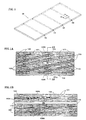
- Fig. 1 is illustrative of a 0.070 (1.78 mm) inch thick panel 98 made in the manner of the foregoing example.
- the four cooling channels created within the panel by the thermal decomposition of the four graphite/epoxy rods inserted into the preform are designated by the reference numeral 99.
- the cross-section of Fig. 1A taken along the line A-A of Fig. 1 , is substantially parallel to the direction of the SiC warp fibers.
- the cross-section of Fig. 1B is a section taken substantially parallel to the direction of the SiC fill fibers and the graphite/epoxy rods.
- the SiC tows of fill fibers are designated by the reference numeral 100; and the SiC tows of warp fibers are designated by the reference numeral 101.
- the matrix material 102 which is a mixture of SiC slurry particulate and melt infiltrated silicon, is disposed between the fibers and has also infiltrated the SiC fibers, as represented in the drawing by gray shading and stippling within the SiC tows.
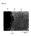
- FIG. 1C A cross-section of a portion of the wall of a cooling channel 99 formed by the process of this example is shown in the photomicrograph of Figure 1C .
- the inside surface of the channel was determined to be coated with a the thin layer 105 of CVI SiC.
- This SiC layer should improve the environmental stability and erosion resistance within the channel and of the composite as a whole.
- the internal surface of the cooling channel 99 has troughs 99A that range in depth from 1 to 7 microns. The troughs replicate the shape, non-uniformities, and surface roughness of individual carbon filaments on the external surface of the pultruded rod prior to decomposition. This suggests the ability to micro-engineer and control critical aspects of cooling channels made by the process of the present invention.
- FIG. 2 shows an enlarged cross-section of a pultruded rod prior to insertion into a preform.
- the carbon filaments extend axially along the length of the rod with no twist, and the major axis of the oval cross-section is about 0.040 inch (1 mm).
- Fig. 2A shows a portion of the cross-section of Fig. 2 greatly magnified such that the individual carbon filaments 108 surrounded by epoxy 108A can be seen. (The individual filaments have a diameter of about 0.25 mil.
- the surface of the cooling channel can be engineered by changing the size and direction of the carbon filaments 108. If the carbon filament bundle within the rod is twisted, the resultant channel surface will have spiraling troughs. Braided carbon tows would create a crisscross pattern.
- the advantage of controlling the surface texture of the cooling channel is that it allows engineering of the heat transfer and fluid flow characteristics of the channels. For instance, channel similar to the one shown in Fig. 1C , wherein the individual filaments were substantially straight, was determined to have a friction factor significantly larger than that of a smooth channel.
- unidirectional, untwisted filaments are preferred for pultruded rods in order to minimize gas infiltration, based upon the foregoing, in some instances it may be more beneficial to create a specific textured surface, such as by twisting or braiding the filaments.
- holes 109A, 109B could be drilled (such as by laser drilling) from the opposite surfaces of the panel to intersect with the channel 99.
- the channel 99 would be sealed closed at its opposite ends 110. Coolant fluid under pressure on the cooler side of the panel would enter the channel 99 through the drilled holes 109A; travel within the channel; and exit via the drilled holes 109B on the other side.
- straight rods were inserted "in plane" into the preform to form straight cooling channels
- other than straight rods may be used to create, for example, curved channels.
- the rods could have a helical shape and be inserted into the preform like a cork screw.
- Short helical rods could be inserted perpendicular to the planar surface and, after being thermally decomposed, create helical channels through the thickness of the panel.
- a flat panel ceramic matrix (silicon carbide) composite woven angle interlock preform was made using the same process and materials as described in the above example, except a weavable, flexible carbon insert was used to create the channel, rather than a graphite/epoxy rod; and the insert was automatically woven into the preform in the warp direction. More specifically, one of the SiC warp fibers was replaced in the weaving loom with a 4000 filament braided carbon tow comprising four individual 1000 filament carbon tows braided together at 22 plaits per inch. The carbon fibers of the tow were made from a polyacrylonitride precursor. The braided tow had an outer diameter of approximately 0.026 inch (0.7 mm).
- the photomicrograph of Fig. 3 is a section taken through the panel in the warp direction substantially parallel to the warp fibers. The full thickness, t, of the panel is shown and was 0.070 inch (1.8 mm).
- the SiC warp fibers are designated by the numeral 101
- the SiC fill fibers are designated by the numeral 100.
- the numeral 120 designates the cooling channel created by thermal decomposition of the braided carbon tow. Note that the channel breaks through the surface 122 of the panel and bends back into the panel, demonstrating the ability of the flexible (weavable) braided carbon insert to change direction without fracturing as it is automatically woven into the preform.
- the braided carbon tow included no carbonaceous filler, and, although it cannot be seen in Fig. 3 , some silicon carbide infiltrated the braid and remained within the channels after oxidation, which is undesirable since the channels are small and may become blocked. Had a carbonaceous filler, such as partially cured epoxy, been used, the channels would have been burned out completely, as had been demonstrated in other tests.
- Figs. 4-6 show a SiC/SiC ceramic matrix composite turbine guide vane 200 for use in a gas turbine engine.
- the vane 200 includes a hollow airfoil 200A defined by a thin wall 201 extending longitudinally between platforms 202A and 202B.
- the internal cavity of the airfoil is designated by the reference numeral 204.
- Pressurized cooling air enters the cavity 204 through the radially inner end of the airfoil, below the platform 202B.
- the radially outer end of the airfoil cavity 204 is closed by an end cap 203.
- the wall 201 has an external surface 205 and an internal surface 206.
- the airfoil has a plurality of transversely extending rows (i.e. each row is in a plane which is transverse to the longitudinal direction) of cooling holes 207 through which cooling fluid from within the cavity 204 pass to convectively cool the wall 201 and to provide film cooling to the surface 205.
- each row of holes 207 within the wall 201, in the plane of each row of holes 207, is a cooling channel 208 that extends around the perimeter of the airfoil.
- the cooling holes 207 in each row of holes intersects the cooling channel 208 associated with its respective row.
- transversely extending rows of holes 209 extend from the internal surface 206 of the airfoil and intersect respective cooling channels 208.
- pressurized cooling fluid from within the cavity 204 passes into the channels 208 via the holes 209. The fluid travels through the channels 208 and exits through the holes 207.
- the airfoil 200A is made in accordance with the teachings of the present invention.
- a preform of the appropriate thickness, size and shape is woven using SiC fibers (such as described with respect to Example 1, above) except where cooling channels 208 are to be formed.
- the SiC fibers of the weaving loom are replaced with braided tows of carbon fibers, such as described with respect to Example 2, except the tows are filled with a thermoset polymer that is only partially cured at the time of weaving.
- the woven preform is placed over a carbon mandrel in a mold having the desired shape of the airfoil; and the preform is consolidated with SiC matrix material by processes well known in the art.
- ceramic matrix composite turbine components may be made using the process of the present invention, such as rotor blades, blade or vane platforms (like the platforms 202A and 202B in Fig. 4 ), and turbine blade root air seals, to name a few.
- Fig. 7 depicts a portion of a gas turbine engine, including a combustion section 301 having a plurality of generally cylindrical SiC/SiC ceramic matrix composite combustor liners 302 (only one of which is shown) spaced about the engine axis 303.
- the liners 302 are made in accordance with the process of the present invention, such as by the process of Example 2.
- Each liner has an inlet 304 and an outlet 305 and defines a combustion space 306 into which fuel is injected via fuel injection apparatus 307.
- the downstream end of the liner 302 is secured to the upstream end of an annular transition duct 308.
- Figs. 8 and 9 are enlarged schematic representations of a section of the wall 310 of the liner 302 at an intermediate point in the fabrication process, which is immediately prior to the decomposition step.
- the stippled portions 311 of Figs. 8 and 9 represent both the SiC matrix material and the woven SiC fiber tows.
- the filled carbon fiber tows are designated by the reference numeral 312.
- the drawing does not show the individual SiC fiber tows that are interwoven with the carbon fiber tows; and, in the cross-section of Fig. 9 , the SiC matrix material is treated as if transparent.
- the wall 310 is 0.10 inch (2.5 mm) thick; and filled carbon fiber tows extend in both the axial direction 313 and the circumferential direction 314, to form a crisscross pattern.
- the carbon fiber tows are about 0.025 inch (0.64 mm) in diameter and are equally spaced from both the radially inwardly facing surface 315 and radially outwardly surface 316 of the liner.
- the tows extending in the fill direction 314 are spaced about 0.10 inch (2.5 mm) apart; and the tows extending in the warp direction 313 are about 0.10 inch (2.5 mm) apart.
- the axial and circumferentially woven carbon fiber tows contact each other at the intersection or crossover points 317.
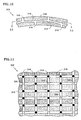
- Figs. 10 and 11 show a section of the finished liner 302, after the carbon fiber tows have been removed by thermal decomposition to form a crisscross patterned grid of cooling channels 318.
- the matrix material and SiC fibers are shown as shaded areas.
- a plurality of 0.025 inch (0.64 mm) diameter coolant outlet passageways and inlet passageways 319, 320, respectively, have been laser drilled into the part from, respectively, the surfaces 315, 316. Both sets of passageways intersect with the channel 318 at selected intersections of the crisscross pattern.
- the coolant inlet passageways 320 are depicted as clear circles, and the coolant outlet passageways are depicted as solid circles.
- none of the inlet passageways are aligned with the outlet passageways, thereby forcing the coolant fluid to traverse at least a portion of the elongated cooling channel.
- pressurized cooling air enters the channel 318 via the holes 320.
- the coolant air travels through various legs of the crisscross pattern of the channel 318 and exits through the outlet holes 319.
- the number of outlet holes is three times the number of inlet holes.
- the spacing between tows and number of coolant holes and their location is likely to vary over the surface of the liner in order to maintain acceptable temperatures at all locations and to minimize the amount of coolant used. Even the carbon fiber tow weave pattern within the preform may be varied to provide different amounts of cooling to various portions of the liner.
- Ceramic matrix composite combustor components examples include combustor panels (e. g. panels spaced inwardly from and attached to the combustor liner to create a double wall) and combustor heat shields.
- FIG. 12 An example of another cooling channel configuration for a ceramic matrix composite part that may be made according to the present invention is shown in the wall section 400 illustrated in Figs. 12 and 13 .
- the cooling channels 401 are shown in perspective, with the balance of the wall material 402 shown stippled.
- Each cooling channel 401 extends from one wall surface 403 to the other wall surface 404 through the entire thickness of the wall.
- the warp direction is designated by the arrow 405.
- the filled carbon fiber tows are warp "threads", woven together with SiC warp and fill threads to form a preform.
- the carbon fiber tows, appropriately located within the preform, would each have the final zigzag shape of the cooling channels.
- the preform is then consolidated with SiC matrix material, and the carbon fiber tows are removed by thermal decomposition, as previously explained.
- pressurized cooling fluid on one side of the wall enters the cooling channels and travels in a zigzag path through the wall until it exits on the other side. If desired, some of the cooling fluid may exit from the edge 406 of the wall.
- One possible set of dimensions for the wall section 400 of this example is a wall thickness of 0.090 inch (2.3 mm) with the cooling channels having a diameter of 0.020 inch (0.5 mm). The distances a, b, c and d would be 0.105 inch (2.7 mm), 0.060 inch (1.5 mm), 0.21 inch (5.3 mm), and 0.30 inch (7.6 mm), respectively.
- the radius of curvature R to the centerline of the channel is on the order of 0.04 inch (1 mm).
- the process is particularly suited for making cooling channels in any thin walled ceramic matrix composite part intended for use at high temperatures.
- the process is suited for making cooling channels in ceramic matrix composite combustor components, more particularly in thin walled ceramic matrix composite combustor, components.
- the process of the invention can produce a substantially planar crisscross pattern of intersecting elongated channels in a part with a thin wall.
Landscapes
- Engineering & Computer Science (AREA)
- Chemical & Material Sciences (AREA)
- Ceramic Engineering (AREA)
- Manufacturing & Machinery (AREA)
- Structural Engineering (AREA)
- Materials Engineering (AREA)
- Organic Chemistry (AREA)
- Chemical Kinetics & Catalysis (AREA)
- Mechanical Engineering (AREA)
- General Engineering & Computer Science (AREA)
- Inorganic Chemistry (AREA)
- Combustion & Propulsion (AREA)
- Ceramic Products (AREA)
- Turbine Rotor Nozzle Sealing (AREA)
- Woven Fabrics (AREA)
Description
- This invention relates to the manufacture of ceramic matrix composite parts having cooling channels therein.
- Ceramic matrix composites("CMC") are well known in the art and may comprise ceramic fibers in a ceramic matrix. CMC are used in high temperature environments, such as in the hot section of a gas turbine engine. For handleability, and to achieve desired mechanical and thermal property orientation in the final product, the ceramic fibers may be woven together to form essentially two-dimensional plies of fiber "cloth", or they may be woven into a three dimensional preform of the desired thickness. The preform and matrix are then consolidated in a mold by any of several well known processes, such as by melt infiltration, chemical vapor infiltration, or pre-ceramic polymer processing.
- One known CMC composition is made using silicon carbide fibers in a silicon carbide matrix (commonly referred to as a SiC/SiC composite). Another well know CMC composition uses SiC fibers in a silicon-nitrogen-carbon matrix (commonly referred to as a SiC/SiNC composite). Although, using current technology, these and other ceramic matrix composites can withstand temperatures as high as 2200°F (1204°C), they still need to be cooled for today's gas turbine applications, and improvements are being sought to even further increase their temperature capabilities. Usually the walls of gas turbine engine components are made as thin as possible to minimize weight and to decrease the "through thickness" thermal stresses. The wall thickness of hollow CMC turbine vanes is usually no more than about 0.1 inch (2.5 mm), and may be considerably less.
- A common method for preventing the degradation of components subject to very high temperatures is to flow cooling fluid through channels or passageways within the component. Current CMC fabrication techniques and materials make it difficult to form curved channels and in-plane internal channels having the requisite shapes, locations, tolerances, and dimensions, especially in-plane small diameter channels for thin walled components.
- It is well known that straight passages or channels extending from an outer surface of the part to the interior or entirely through the part can be formed by laser machining after consolidating the fiber preform and matrix material; however, laser drilling has its limitations since curved channels cannot be laser drilled, and channels oriented substantially parallel to a wall surface (i.e. in-plane) cannot be made by laser drilling in thin walled parts, unless drilled into an edge. In any event, laser drilling is practical only for straight passages of less than about 0.5 inch (12.7 mm) long.
- Voids or channels of various shapes may also be created within CMC parts by the steps of (a) inserting either carbon rods or graphite paper between the fiber plies as they are being laid-up in the mold, and (b) burning-out (thermal decomposition by oxidation) the carbon after consolidation of the preform and matrix material. The use of carbon rods is not practical for long, narrow or curved channels since they are brittle and mechanically weak (i.e., a 0.02 inch (0.5 mm) diameter carbon rod has a tensile strength of less then 1.0 ksi), breaking easily during the matrix consolidation step. Graphite paper also has a low mechanical strength and tendency to break during handling and weaving (i.e.,
- According to the invention there is provided a process for manufacturing a ceramic matrix composite part as claimed in
claim 1. - a tensile strength of less than about 1.0 ksi). Further, neither the use of carbon rods nor graphite paper is suited to an automated manufacturing process, especially where the channels are long, have small diameters, must be carefully located, may need to interconnect with each other, or may need to have a small radius of curvature. More specifically, in view of manufacturing limitations, it has not been possible to make ceramic matrix composite parts with small diameter (i.e. less than and effective diameter of about 0.10 inch (2.5 mm) elongated channels that include a change in direction requiring a radius of curvature smaller than about 6.0 inches (152 mm). Thus, zig-zag channels could not be formed. Also, it was not possible to form a complex pattern of intersecting elongated channels, such as an intersecting grid of channels within a thin wall. As used herein and in the appended claims, "elongated" means having a length to "effective diameter" ratio of at least about 50. Effective diameter is the diameter of a circle having the same cross sectional area as the channel in question.
- In a process disclosed herein, inserts having essentially the size and shape of elongated channels to be formed within the part are disposed at a desired location within a woven ceramic fiber preform. The inserts comprise a plurality of carbon fibers surrounded by a carbonaceous filler. After the inserts are in place, a ceramic matrix material is added and the fiber preform is consolidated with the matrix material. The consolidated part is then heated to thermally decompose the inserts leaving elongated channels within the part. The inserts may be rods of carbon fibers or may be flexible, weaveable carbon fiber tows.
- During the consolidation step, the carbonaceous filler material fills the interstices between the carbon fibers of the inserts and acts as a protective shell around individual carbon fibers and around any bundles of those fibers that comprise the insert. This inhibits process gases and matrix material from entering voids between the carbon fibers and from directly contacting the carbon fibers. The matrix material, if able to contact the fibers, would inhibit the oxidation of the carbonaceous inserts by depositing a non-oxidizable coating on the fibers, making successful removal of the carbon fiber difficult, if not impossible. Any matrix material that works its way between the carbon fibers will not be removed during thermal decomposition. Thus, by way of example, in the chemical vapor infiltration (CVI) consolidation of a SiC/SiC composite, the carbonaceous filler inhibits the methyltrichlorosilane gas from contacting the carbon fibers and depositing silicon carbide thereon.
- As used herein and in the claims, a "carbonaceous" filler material is a material that produces at least about 10% carbon residue, by weight, upon thermal decomposition in a non-oxidizing environment. Preferably the filler will form a high surface area material upon decomposition, such as a film or closed cell foam that will inhibit infiltration of the matrix material between the carbon fibers. Without intending to limit the same, examples of carbonaceous filler materials usable in the process of the present invention are colloidal graphite (with or without a binder) and polymers containing sufficient carbon molecules to satisfy the definition of "carbonaceous", such as epoxy, silicone, and polyacrylonitrile.
- The process of the present invention is particularly suited for (although not limited to) forming in-plane elongated channels of small effective diameter (i.e. small cross sectional area) between the surfaces of thin walled components, and for closely locating and closely spacing those channels. Small effective diameter" means a cross section having an effective diameter of less than about 0.10 inch (2.5 mm). The effective diameters may be no greates than 0.05 inch (1.3mm) Parts made by the process of the invention are particularly unique in that they may be made with elongated channels of small effective diameter, wherein the channels may have a radius of curvature of less than 1.0 inch (25.4 mm), less than 0.5inch (12.7mm) and even less than 0.02 inch (0.5 mm). The weavable braided fibers used in the process of the present invention to form the channels have actually been wrapped around a pin of .015 inch (0.38 mm) diameter without major damage and without significant flattening (which would result in a smaller cross sectional channel area around sharp curves). This makes the process of the present invention particularly suited for making thin walled parts having a plurality of curved, elongated channels of small effective diameter. By a "thin wall" it is meant a wall having a thickness of 0.25 inch (6.3 mm) or less.
- In accordance with one embodiment of the invention, the inserts used in the fabrication process are individual rods of carbon fibers filled with a thermoset polymeric material that is cured in order that the rods hold a rigid cross-sectional shape and can be handled without breaking. The fibers are preferably continuous, substantially unidirectional carbon fiber tows since continuous unidirectional fibers can be packed more densely into the same rod volume. Rods of this type may be made by pultrusion ("pultruded" rods) and are currently commercially available, although used for applications such as to reinforce fishing poles. Pultruded graphite/epoxy rods (comprising continuous graphite filaments) are commercially available in a variety of diameters from 0.010 inch (0.25 mm) to 0.04 inch (1 mm), and higher. They may be made with a variety of cross-sectional shapes, so channels of different cross sectional shapes may be formed. The rods may be inserted by hand into or between plies of woven ceramic fibers; or they may be inserted in the fill direction into either a two or three-dimensional preform during the weaving process. In the latter case, the rods are preferably used where minimal bending is required, such as the fill fibers in an angle interlock weave. That is because rods incorporating a cured thermoset filler have limited flexibility and may not be pliable enough to bend around sharp curvatures without breaking.
- The volume percent of fibres in the rods may be between 50 and 65%.
- In a preferred embodiment, the inserts are flexible, weavable inserts. The weavable inserts are comprised of carbon tows filled with a flexible carbonaceous material rather than a cured thermoset polymeric material. Preferably the tows are braided or twisted to help the insert retain a generally circular or oval cross-sectional shape during the weaving operation. In any case, the filled tows are flexible (as compared to the above described rods made with the cured thermoset polymeric material) and can be woven into a preform by standard weaving machines as either or both warp and weft (fill) filaments.
- After consolidating the preform with the matrix material, the carbon tows and carbonaceous filler are removed by thermal decomposition, leaving channels in their place within the CMC part. One particular advantage of being able to essentially "weave" a channel in any direction, is that a complex pattern of interconnected channels may be formed; and the channels may be curved and thus may change directions sharply, if desired.
- One example of a flexible carbonaceous filler is carbon particles within a carrier, such as a colloid of graphite. Although not required, a binder, such as colloidal silica, is beneficial as it helps keep the carbon particles in place after the fluid carrier has evaporated during processing. Another example of a flexible carbonaceous filler is a thermoplastic polymeric material. RTV silicone is one example of such a material.
- In yet another example, the filler may be a partially cured thermoset polymer, which is preferably an epoxy. The filled carbon tows and the ceramic fibers are woven together to form the preform while the thermoset polymer is in a partially cured state prior to full molecular cross-linking. The preform and matrix are then consolidated, during which time the epoxy cures. The channels are then formed by thermally decomposing the filled carbon tows. While the epoxy is in the partially cured state, the carbon tows remain sufficiently flexible to be "weaveable" using automated equipment. Further, the use of epoxy avoids residue build-up on the weaving equipment, as may occur when colloidal graphite is the filler. Yet another advantage is that an epoxy does not produce non-oxidizable constituents.
- The foregoing features and advantages of the present invention will become more apparent in light of the following detailed description of exemplary embodiments thereof as illustrated in the accompanying drawings.
-
-
Fig. 1 is a perspective view, not to scale, representative of a SiC/SiC ceramic composite matrix panel with channels formed therein made in accordance with the teachings of the present invention. -
Fig. 1A is a schematic, greatly enlarged sectional view (based upon a photomicrograph) taken generally along the line A-A ofFig. 1 . -
Fig. 1B is a schematic, sectional view (based upon a photomicrograph) taken along the line B-B ofFig. 1A . -
Fig. 1C is a photomicrograph of a portion of the wall of a channel formed within a SiC/SiC ceramic matrix composite made in accordance with the teachings of the present invention. -
Fig. 2 is a photomicrograph of a cross-section of a carbon fiber, graphite/epoxy filled rod used in the process of the present invention. -
Fig. 2A is a photomicrograph of an enlarged portion of an area of a cross-section through a rod like that ofFig. 2 , showing the individual carbon filaments that comprise the rod. -
Fig. 3 is a photomicrograph of a section through the thickness of a SiC/SiC ceramic matrix composite panel showing a channel made using a weavable braided carbon tow. -
Fig. 4 is a perspective view illustrative of a gas turbine engine stator vane made in accordance with the teachings of the present invention. -
Fig. 5 is a sectional view taken along the line 5-5 ofFig. 4 . -
Fig. 6 is an sectional view, taken generally along the line 6-6 ofFig. 5 . -
Fig. 7 is an illustrative view, partly in section, of a portion of a gas turbine engine, including the combustion section. -
Fig. 8 is a sectional view, greatly enlarged, taken along the line 8-8 ofFig. 7 through the wall of a combustor liner made in accordance with the teachings of the present invention, but illustrating the appearance of that liner at an intermediate point during the fabrication process. -
Fig. 9 is a sectional view taken generally along the line 9-9 ofFig. 8 . -
Fig. 10 is a sectional view, greatly enlarged, taken along the line 8-8 ofFig. 7 through the wall of a combustor liner made in accordance with the teachings of the present invention, showing cooling channels within the wall. -
Fig. 11 is a sectional view taken along the line 11-11 ofFig. 10 . -
Fig. 12 a perspective view of a wall, illustrating an alternate cooling channel configuration which may be made in accordance with the teachings of the present invention. -
Fig. 13 is a sectional view, rotated 90°, taken along the line 13-13 ofFig. 12 . - In one test, a flat panel SiC/SiC ceramic matrix composite, having a thickness of approximately 0.070 inch (1.78 mm), was made as follows:
- An angle interlock preform was machine woven using SiC tows of Hi-Nicalon Type S fiber, which is a stoichiometric SiC fiber from Nippon Carbon Company. Each fiber tow comprised 500 filaments, and each filament had a diameter of about 13 microns. In this example, the tows were oval in cross section, having a major axis dimension of about 0.031 inch (0.79 mm) and a minor axis dimension of about 0.007 inch (0.17 mm). In other experiments, SiC tows with diameters ranging from between 0.010 and 0.025 inch (0.25-0.64 mm) were used successfully. The cross-sectional shape and the size of the SiC tows are not critical to the present invention.
- The woven preform in this example had five layers of SiC fill (weft) fibers spaced at 128 fibers per inch and five layers of SiC warp fibers spaced at 143 fibers per inch. The total fiber volume was 28 volume percent with 15 volume percent in the warp direction and 13 volume percent in the fill direction. The angle of the warp fibers was 15°.
- At four locations in a 6" x 9" x 0.070" (152 x 229 x 1.78 mm) panel of the woven preform, straight graphite/epoxy pultruded rods, having an elliptical cross-section, were inserted at the fill sites in place of the SiC Type S fiber. The ellipse major axis of each rod was about 0.040 inch (1 mm), and the minor axis was about 0.020 inch (0.5 mm). The insertion of the rod was done by stopping the loom; removing a SiC fill tow and in its place inserting a graphite/epoxy rod by hand. The rod was approximately 65 volume percent Pyrofil TR50 continuous carbon (graphite) filaments from Grafil Inc. and 35 volume percent epoxy. The epoxy resin was bisphenol F, and the curing agent was inidazole. Although elliptical rods were used in this example, rods of other cross-sectional shapes may be used in order to make channels having specific cross-sectional shapes.
- The woven preform was consolidated with a matrix material by standard melt infiltration silicon carbide/silicon carbide (MI SiC/SiC) processing, as follows: The fiber preform was placed between graphite tooling. The tooled preform was heated in a furnace and a boron nitride fiber/matrix interface layer was applied to the fiber by chemical vapor infiltration. The graphite tooling was removed. The preform was placed in another furnace to deposit the silicon carbide matrix throughout the heated preform via decomposition of methyltrichlorosilane gas - a process called chemical vapor infiltration (CVI). The methyltrichlorosilane gas does not, however, penetrate the graphite/epoxy rods. Further densification of the matrix region was accomplished by slurry casting an aqueous solution of SiC particles. The final densification of the composite was completed by applying silicon to the surface of the panel and heating in a furnace - a process called melt infiltration of silicon.
- The last step is the creation of the internal cooling channels by the oxidative removal of the remains of the graphite/epoxy rod material. To that end, the composite panel was placed in a furnace under an air atmosphere at 650°C and held for 48 hours.
-
Fig. 1 is illustrative of a 0.070 (1.78 mm) inchthick panel 98 made in the manner of the foregoing example. The four cooling channels created within the panel by the thermal decomposition of the four graphite/epoxy rods inserted into the preform are designated by thereference numeral 99. The cross-section ofFig. 1A , taken along the line A-A ofFig. 1 , is substantially parallel to the direction of the SiC warp fibers. And the cross-section ofFig. 1B is a section taken substantially parallel to the direction of the SiC fill fibers and the graphite/epoxy rods. - The SiC tows of fill fibers are designated by the
reference numeral 100; and the SiC tows of warp fibers are designated by thereference numeral 101. Thematrix material 102, which is a mixture of SiC slurry particulate and melt infiltrated silicon, is disposed between the fibers and has also infiltrated the SiC fibers, as represented in the drawing by gray shading and stippling within the SiC tows. - A cross-section of a portion of the wall of a cooling
channel 99 formed by the process of this example is shown in the photomicrograph ofFigure 1C . The inside surface of the channel was determined to be coated with a thethin layer 105 of CVI SiC. This SiC layer should improve the environmental stability and erosion resistance within the channel and of the composite as a whole. In this example the internal surface of the coolingchannel 99 hastroughs 99A that range in depth from 1 to 7 microns. The troughs replicate the shape, non-uniformities, and surface roughness of individual carbon filaments on the external surface of the pultruded rod prior to decomposition. This suggests the ability to micro-engineer and control critical aspects of cooling channels made by the process of the present invention. - Micro-engineering of the surface may be better understood with reference to
Figs. 2 and 2A. Fig. 2 shows an enlarged cross-section of a pultruded rod prior to insertion into a preform. In this rod the carbon filaments extend axially along the length of the rod with no twist, and the major axis of the oval cross-section is about 0.040 inch (1 mm).Fig. 2A shows a portion of the cross-section ofFig. 2 greatly magnified such that theindividual carbon filaments 108 surrounded byepoxy 108A can be seen. (The individual filaments have a diameter of about 0.25 mil. (.006 mm)) Since the troughs replicate the carbon filaments at the surface of the rod (or at the surface of flexible, braided, carbon tows, for example), the surface of the cooling channel can be engineered by changing the size and direction of thecarbon filaments 108. If the carbon filament bundle within the rod is twisted, the resultant channel surface will have spiraling troughs. Braided carbon tows would create a crisscross pattern. The advantage of controlling the surface texture of the cooling channel is that it allows engineering of the heat transfer and fluid flow characteristics of the channels. For instance, channel similar to the one shown inFig. 1C , wherein the individual filaments were substantially straight, was determined to have a friction factor significantly larger than that of a smooth channel. Although, as previously stated, unidirectional, untwisted filaments are preferred for pultruded rods in order to minimize gas infiltration, based upon the foregoing, in some instances it may be more beneficial to create a specific textured surface, such as by twisting or braiding the filaments. - If the panel of
Fig.1 were to be used as the wall of a component subject to extremely high temperatures on one side, holes 109A, 109B (shown using dotted lines inFigs. 1A and 1B ) could be drilled (such as by laser drilling) from the opposite surfaces of the panel to intersect with thechannel 99. Thechannel 99 would be sealed closed at its opposite ends 110. Coolant fluid under pressure on the cooler side of the panel would enter thechannel 99 through the drilledholes 109A; travel within the channel; and exit via the drilledholes 109B on the other side. - Although, in this example, straight rods were inserted "in plane" into the preform to form straight cooling channels, other than straight rods may be used to create, for example, curved channels. For example, the rods could have a helical shape and be inserted into the preform like a cork screw. Short helical rods could be inserted perpendicular to the planar surface and, after being thermally decomposed, create helical channels through the thickness of the panel.
- In another test, a flat panel ceramic matrix (silicon carbide) composite woven angle interlock preform was made using the same process and materials as described in the above example, except a weavable, flexible carbon insert was used to create the channel, rather than a graphite/epoxy rod; and the insert was automatically woven into the preform in the warp direction. More specifically, one of the SiC warp fibers was replaced in the weaving loom with a 4000 filament braided carbon tow comprising four individual 1000 filament carbon tows braided together at 22 plaits per inch. The carbon fibers of the tow were made from a polyacrylonitride precursor. The braided tow had an outer diameter of approximately 0.026 inch (0.7 mm).
- The photomicrograph of
Fig. 3 is a section taken through the panel in the warp direction substantially parallel to the warp fibers. The full thickness, t, of the panel is shown and was 0.070 inch (1.8 mm). As in the prior example, the SiC warp fibers are designated by the numeral 101, and the SiC fill fibers are designated by the numeral 100. The numeral 120 designates the cooling channel created by thermal decomposition of the braided carbon tow. Note that the channel breaks through thesurface 122 of the panel and bends back into the panel, demonstrating the ability of the flexible (weavable) braided carbon insert to change direction without fracturing as it is automatically woven into the preform. - In the test of this Example 2, the braided carbon tow included no carbonaceous filler, and, although it cannot be seen in
Fig. 3 , some silicon carbide infiltrated the braid and remained within the channels after oxidation, which is undesirable since the channels are small and may become blocked. Had a carbonaceous filler, such as partially cured epoxy, been used, the channels would have been burned out completely, as had been demonstrated in other tests. -
Figs. 4-6 show a SiC/SiC ceramic matrix compositeturbine guide vane 200 for use in a gas turbine engine. Thevane 200 includes ahollow airfoil 200A defined by athin wall 201 extending longitudinally betweenplatforms reference numeral 204. Pressurized cooling air enters thecavity 204 through the radially inner end of the airfoil, below theplatform 202B. The radially outer end of theairfoil cavity 204 is closed by an end cap 203. Thewall 201 has anexternal surface 205 and aninternal surface 206. The airfoil has a plurality of transversely extending rows (i.e. each row is in a plane which is transverse to the longitudinal direction) ofcooling holes 207 through which cooling fluid from within thecavity 204 pass to convectively cool thewall 201 and to provide film cooling to thesurface 205. - As best shown in
Figs. 5 and 6 , within thewall 201, in the plane of each row ofholes 207, is acooling channel 208 that extends around the perimeter of the airfoil. The cooling holes 207 in each row of holes intersects the coolingchannel 208 associated with its respective row. Similarly, transversely extending rows ofholes 209 extend from theinternal surface 206 of the airfoil and intersectrespective cooling channels 208. In operation, pressurized cooling fluid from within thecavity 204 passes into thechannels 208 via theholes 209. The fluid travels through thechannels 208 and exits through theholes 207. - The
airfoil 200A is made in accordance with the teachings of the present invention. Using the well know pin weaving technique, a preform of the appropriate thickness, size and shape is woven using SiC fibers (such as described with respect to Example 1, above) except where coolingchannels 208 are to be formed. Where the cooling channels are to be located the SiC fibers of the weaving loom are replaced with braided tows of carbon fibers, such as described with respect to Example 2, except the tows are filled with a thermoset polymer that is only partially cured at the time of weaving. The woven preform is placed over a carbon mandrel in a mold having the desired shape of the airfoil; and the preform is consolidated with SiC matrix material by processes well known in the art. - Although not described, other ceramic matrix composite turbine components may be made using the process of the present invention, such as rotor blades, blade or vane platforms (like the
platforms Fig. 4 ), and turbine blade root air seals, to name a few. -
Fig. 7 depicts a portion of a gas turbine engine, including acombustion section 301 having a plurality of generally cylindrical SiC/SiC ceramic matrix composite combustor liners 302 (only one of which is shown) spaced about theengine axis 303. Theliners 302 are made in accordance with the process of the present invention, such as by the process of Example 2. Each liner has aninlet 304 and anoutlet 305 and defines acombustion space 306 into which fuel is injected viafuel injection apparatus 307. The downstream end of theliner 302 is secured to the upstream end of anannular transition duct 308. The combustion gases leave thecombustion space 306, pass through thetransition duct 308, and enter theengine turbine section 309. -
Figs. 8 and 9 are enlarged schematic representations of a section of thewall 310 of theliner 302 at an intermediate point in the fabrication process, which is immediately prior to the decomposition step. The stippledportions 311 ofFigs. 8 and 9 , represent both the SiC matrix material and the woven SiC fiber tows. The filled carbon fiber tows are designated by thereference numeral 312. For purposes of clearly showing the weave pattern of the carbon fiber tows, the drawing does not show the individual SiC fiber tows that are interwoven with the carbon fiber tows; and, in the cross-section ofFig. 9 , the SiC matrix material is treated as if transparent. - In this embodiment, the
wall 310 is 0.10 inch (2.5 mm) thick; and filled carbon fiber tows extend in both theaxial direction 313 and thecircumferential direction 314, to form a crisscross pattern. The carbon fiber tows are about 0.025 inch (0.64 mm) in diameter and are equally spaced from both the radially inwardly facingsurface 315 and radially outwardly surface 316 of the liner. The tows extending in thefill direction 314 are spaced about 0.10 inch (2.5 mm) apart; and the tows extending in thewarp direction 313 are about 0.10 inch (2.5 mm) apart. The axial and circumferentially woven carbon fiber tows contact each other at the intersection or crossover points 317. -
Figs. 10 and 11 show a section of thefinished liner 302, after the carbon fiber tows have been removed by thermal decomposition to form a crisscross patterned grid of coolingchannels 318. The matrix material and SiC fibers are shown as shaded areas. Also, a plurality of 0.025 inch (0.64 mm) diameter coolant outlet passageways andinlet passageways surfaces channel 318 at selected intersections of the crisscross pattern. InFig. 11 thecoolant inlet passageways 320 are depicted as clear circles, and the coolant outlet passageways are depicted as solid circles. - In this particular embodiment, none of the inlet passageways are aligned with the outlet passageways, thereby forcing the coolant fluid to traverse at least a portion of the elongated cooling channel. (Note that the dimensions given above for the combustor liner embodiment of
Figs. 7-11 are exemplary only, and do not represent parts that were actually fabricated by the process of the present invention.) - In operation, pressurized cooling air enters the
channel 318 via theholes 320. The coolant air travels through various legs of the crisscross pattern of thechannel 318 and exits through the outlet holes 319. In the section of liner shown inFigs. 10 and 11 , the number of outlet holes is three times the number of inlet holes. - In actuality, the spacing between tows and number of coolant holes and their location is likely to vary over the surface of the liner in order to maintain acceptable temperatures at all locations and to minimize the amount of coolant used. Even the carbon fiber tow weave pattern within the preform may be varied to provide different amounts of cooling to various portions of the liner.
- Examples of other ceramic matrix composite combustor components that may be made by the process of the present invention are combustor panels (e. g. panels spaced inwardly from and attached to the combustor liner to create a double wall) and combustor heat shields.
- An example of another cooling channel configuration for a ceramic matrix composite part that may be made according to the present invention is shown in the
wall section 400 illustrated inFigs. 12 and 13 . For purposes of clarity, inFig. 12 the coolingchannels 401 are shown in perspective, with the balance of thewall material 402 shown stippled. Each coolingchannel 401 extends from onewall surface 403 to theother wall surface 404 through the entire thickness of the wall. In the fabrication of this part the warp direction is designated by thearrow 405. During fabrication, the filled carbon fiber tows are warp "threads", woven together with SiC warp and fill threads to form a preform. The carbon fiber tows, appropriately located within the preform, would each have the final zigzag shape of the cooling channels. The preform is then consolidated with SiC matrix material, and the carbon fiber tows are removed by thermal decomposition, as previously explained. - During operation of the finished part, pressurized cooling fluid on one side of the wall enters the cooling channels and travels in a zigzag path through the wall until it exits on the other side. If desired, some of the cooling fluid may exit from the
edge 406 of the wall. One possible set of dimensions for thewall section 400 of this example is a wall thickness of 0.090 inch (2.3 mm) with the cooling channels having a diameter of 0.020 inch (0.5 mm). The distances a, b, c and d would be 0.105 inch (2.7 mm), 0.060 inch (1.5 mm), 0.21 inch (5.3 mm), and 0.30 inch (7.6 mm), respectively. The radius of curvature R to the centerline of the channel is on the order of 0.04 inch (1 mm). - Although the invention has been described and illustrated with respect to exemplary embodiments thereof, it should be understood by those skilled in the art that the foregoing and various other changes, omissions and additions may be made without departing from the scope of the invention as defined by the claims. More specifically, the process is particularly suited for making cooling channels in any thin walled ceramic matrix composite part intended for use at high temperatures. For example the process is suited for making cooling channels in ceramic matrix composite combustor components, more particularly in thin walled ceramic matrix composite combustor, components.
- The process of the invention can produce a substantially planar crisscross pattern of intersecting elongated channels in a part with a thin wall.
Claims (32)
- A process for manufacturing a ceramic matrix composite part having elongated channels therein, including the steps of:A. forming a preform, including the steps of weaving together ceramic fibers and inserting a plurality of elongated carbonaceous inserts within the woven ceramic fibers at the locations where the channels are desired, the inserts comprising carbon fibers surrounded by a carbonaceous filler;B. consolidating the preform and a ceramic matrix material to a desired shape; andC. removing the elongated inserts after the consolidation step by thermally decomposing the inserts, leaving elongated channels in place of the inserts.
- The process according to claim 1, wherein the carbon fibers are continuous filaments.
- The process according to claim 1 or 2, wherein the inserts are flexible and are woven into the preform using automated weaving apparatus.
- The process according to claim 3, wherein the carbon fibers are woven to form a crisscross pattern with the fibers contacting each other at crossover points, and the step of removing the inserts creates an interconnected crisscross patterned cooling channel.
- The process according to any preceding claim, wherein the carbonaceous filler includes colloidal graphite.
- The process according to claim 5, wherein the filler includes a binder for the colloidal graphite.
- The process according to any preceding claim wherein the ceramic fibers are silicon carbide fibers.
- The process according to any preceding claim,
wherein the part has a thin wall of ceramic matrix composite material having opposing surfaces, and the elongated channels are formed within the thin wall, including the step of drilling at least one cooling passage from at least one of said opposing surfaces into the elongated channel. - The process according to claim 2, wherein the inserts are rods of continuous carbon fibers within a cured, thermoset polymeric carbonaceous filler material.
- The process according to claim 9, wherein the polymeric material is epoxy.
- The process according to claim 9 or 10, wherein the rods are pultruded rods.
- The process according to claim 3, wherein the continuous filament carbon fibers are in the form of carbon fiber tows.
- The process according to claim 12, wherein the carbonaceous filler is a thermoplastic polymeric material.
- The process according to claim 12 or 13, wherein the carbonaceous filler is a thermoset polymeric material, and, as the carbon fiber tows are being woven, the polymeric material is only partially cured such that the tows are flexible during weaving.
- The process according to claim 12, 13 or 14 wherein the carbon fiber tows are braided together.
- The process according to claim 12, 13 or 14 wherein the continuous filaments comprising the carbon tows are twisted together.
- The process according to claim 6, wherein the binder is silicone.
- The process according to claim 6, wherein the continuous filament carbon fibers are in the form of carbon fiber tows.
- The process according to claim 9, wherein the volume percent of fibers in the rod is between 50 and 65%.
- The process according to claim 19, wherein the rods are helical.
- The process of any preceding claim wherein the ceramic matrix composite part has first and second spaced apart surfaces defining a thin wall, and the channels formed by the step of thermally decomposing the carbon fibers during the manufacturing process include elongated portions in the plane of said wall between said surfaces, said wall including passageways having openings at said surfaces and interconnecting with said elongated channel portions to enable the passage of fluid through said wall via said passageways and elongated channel portions.
- The process according to claim 3, wherein the part includes a plurality of elongated channels therein, wherein said channels are elliptical and have an effective diameter of no greater than 0.10 inch (2.5 mm) and include at least one change of direction with radius of curvature of less than 1.0 inch (25.4 mm).
- The process according to claim 22, wherein said channels have an effective diameter of no greater than 0.05 inch (1.3 mm) and at least one of said channels includes a radius of curvature of less than 0.50 inch (12.7 mm).
- The process according to any preceding claim, wherein said part has a thin wall, and said thin wall includes therewithin a substantially planar crisscross pattern of elongated channels that intersect.
- The process according to any preceding claim, wherein said part has first and second spaced apart surfaces defining a thin wall, and the channels formed by the step of thermally decomposing the carbon fibers during the manufacturing process are elongated channels extending in a zig-zag pattern through said thin wall from said first to said second surface.
- The process according to claim 25, wherein said channel has an effective diameter of no greater than 0.05 inch (1.3 mm), and includes at least one change of direction with a radius of curvature of less than 1.0 inch (25.4 mm).
- The process of any preceding claim wherein said part is a thin walled ceramic matrix composite combustor component.
- The process of any of claims 1 to 26 wherein said part is a ceramic matrix composite combustor component.
- The process of any of claims 1 to 26 wherein said part is a thin walled ceramic matrix composite combustor liner.
- The process according to any of claims 1 to 26 wherein said part is a ceramic matrix composite combustor liner.
- The process according to any of claims 1 to 26 wherein said part is a thin walled ceramic matrix composite turbine airfoil.
- A ceramic matrix composite part made according to the process of any preceding claim.
Applications Claiming Priority (2)
| Application Number | Priority Date | Filing Date | Title |
|---|---|---|---|
| US739722 | 1985-05-31 | ||
| US09/739,722 US6627019B2 (en) | 2000-12-18 | 2000-12-18 | Process for making ceramic matrix composite parts with cooling channels |
Publications (2)
| Publication Number | Publication Date |
|---|---|
| EP1215183A1 EP1215183A1 (en) | 2002-06-19 |
| EP1215183B1 true EP1215183B1 (en) | 2009-04-01 |
Family
ID=24973500
Family Applications (1)
| Application Number | Title | Priority Date | Filing Date |
|---|---|---|---|
| EP01310556A Expired - Lifetime EP1215183B1 (en) | 2000-12-18 | 2001-12-18 | Ceramic matrix composite parts with channels and process of making the same |
Country Status (4)
| Country | Link |
|---|---|
| US (1) | US6627019B2 (en) |
| EP (1) | EP1215183B1 (en) |
| JP (1) | JP2002234777A (en) |
| DE (1) | DE60138173D1 (en) |
Cited By (1)
| Publication number | Priority date | Publication date | Assignee | Title |
|---|---|---|---|---|
| US11486578B2 (en) | 2020-05-26 | 2022-11-01 | Raytheon Technologies Corporation | Multi-walled structure for a gas turbine engine |
Families Citing this family (112)
| Publication number | Priority date | Publication date | Assignee | Title |
|---|---|---|---|---|
| FR2852003B1 (en) * | 2003-03-04 | 2005-05-27 | Snecma Propulsion Solide | PROCESS FOR PRODUCING A MULTIPERFORATED PART IN CERAMIC MATRIX COMPOSITE MATERIAL |
| EP1462613A1 (en) * | 2003-03-26 | 2004-09-29 | Siemens Aktiengesellschaft | Coolable coating |
| US7094021B2 (en) * | 2004-02-02 | 2006-08-22 | General Electric Company | Gas turbine flowpath structure |
| US7687016B1 (en) * | 2004-02-13 | 2010-03-30 | The United States Of America As Represented By The Administrator Of National Aeronautics And Space Administration | Methods for producing silicon carbide architectural preforms |
| US7464554B2 (en) * | 2004-09-09 | 2008-12-16 | United Technologies Corporation | Gas turbine combustor heat shield panel or exhaust panel including a cooling device |
| US7247212B2 (en) * | 2004-12-21 | 2007-07-24 | General Electric Company | Orthogonal weaving for complex shape preforms |
| US7332049B2 (en) * | 2004-12-22 | 2008-02-19 | General Electric Company | Method for fabricating reinforced composite materials |
| US7431978B2 (en) * | 2004-12-22 | 2008-10-07 | General Electric Company | Reinforced matrix composite containment duct |
| US7335012B2 (en) * | 2004-12-22 | 2008-02-26 | General Electric Company | Apparatus for fabricating reinforced composite materials |
| US7549840B2 (en) * | 2005-06-17 | 2009-06-23 | General Electric Company | Through thickness reinforcement of SiC/SiC CMC's through in-situ matrix plugs manufactured using fugitive fibers |
| US7754126B2 (en) * | 2005-06-17 | 2010-07-13 | General Electric Company | Interlaminar tensile reinforcement of SiC/SiC CMC's using fugitive fibers |
| US8313056B2 (en) | 2005-07-19 | 2012-11-20 | United Technologies Corporation | Engine heat exchanger with thermoelectric generation |
| JP4635183B2 (en) * | 2005-11-09 | 2011-02-16 | 独立行政法人 宇宙航空研究開発機構 | Wide area thermal protection technology by airflow leaching cooling using inclined porous ceramics composite |
| US7302989B1 (en) * | 2006-06-06 | 2007-12-04 | Siemens Power Generation, Inc. | Modular mold system with ceramic inserts |
| US7581924B2 (en) | 2006-07-27 | 2009-09-01 | Siemens Energy, Inc. | Turbine vanes with airfoil-proximate cooling seam |
| US7488157B2 (en) | 2006-07-27 | 2009-02-10 | Siemens Energy, Inc. | Turbine vane with removable platform inserts |
| FR2909297B1 (en) * | 2006-11-30 | 2010-03-05 | Snecma | METHOD FOR LASER DRILLING OF A PIECE OF COMPOSITE MATERIAL WITH CERAMIC MATRIX, HOLE OBTAINED BY THIS PROCESS, PIECE OF COMPOSITE MATERIAL WITH CERAMIC MATRIX COMPRISING IT, TURBOREACTOR COMPRISING SUCH A PIECE |
| US8771604B2 (en) * | 2007-02-06 | 2014-07-08 | Aerojet Rocketdyne Of De, Inc. | Gasifier liner |
| US20080207075A1 (en) * | 2007-02-22 | 2008-08-28 | Siemens Power Generation, Inc. | Optimized fabric lay-up for improved ceramic matrix composites |
| US20090014926A1 (en) * | 2007-07-09 | 2009-01-15 | Siemens Power Generation, Inc. | Method of constructing a hollow fiber reinforced structure |
| US8974891B2 (en) | 2007-10-26 | 2015-03-10 | Coi Ceramics, Inc. | Thermal protection systems comprising flexible regions of inter-bonded lamina of ceramic matrix composite material and methods of forming the same |
| US7832972B2 (en) * | 2008-03-05 | 2010-11-16 | United Technologies Corporation | Internal pocket fastener system for ceramic matrix composites |
| FR2939129B1 (en) * | 2008-11-28 | 2014-08-22 | Snecma Propulsion Solide | TURBOMACHINE TURBINE IN COMPOSITE MATERIAL AND PROCESS FOR MANUFACTURING THE SAME. |
| US9062562B2 (en) * | 2008-11-28 | 2015-06-23 | Herakles | Composite material turbomachine engine blade or vane, compressor stator segment or turbine nozzle segment incorporating such vanes and method for manufacturing same |
| US8522560B2 (en) * | 2009-03-25 | 2013-09-03 | United Technologies Corporation | Fuel-cooled heat exchanger with thermoelectric device compression |
| US8453456B2 (en) * | 2009-03-25 | 2013-06-04 | United Technologies Corporation | Fuel-cooled flexible heat exchanger with thermoelectric device compression |
| US20100272953A1 (en) * | 2009-04-28 | 2010-10-28 | Honeywell International Inc. | Cooled hybrid structure for gas turbine engine and method for the fabrication thereof |
| US8899939B2 (en) | 2009-12-23 | 2014-12-02 | General Electric Company | Process for producing a ceramic matrix composite article and article formed thereby |
| US20110151248A1 (en) * | 2009-12-23 | 2011-06-23 | Paul Stephen Manicke | Ceramic Matrix Composite Precursor Slurry Compositions And Sheet Molding Compound |
| FR2955609B1 (en) | 2010-01-26 | 2012-04-27 | Snecma | AUBE COMPOSITE WITH INTERNAL CHANNELS |
| US8801886B2 (en) * | 2010-04-16 | 2014-08-12 | General Electric Company | Ceramic composite components and methods of fabricating the same |
| US9033673B2 (en) * | 2010-06-28 | 2015-05-19 | Herakles | Turbomachine blade or vane having complementary asymmetrical geometry |
| US9057523B2 (en) * | 2011-07-29 | 2015-06-16 | United Technologies Corporation | Microcircuit cooling for gas turbine engine combustor |
| US10041354B2 (en) | 2011-09-14 | 2018-08-07 | General Electric Company | Blade and method for manufacturing blade |
| US8980435B2 (en) | 2011-10-04 | 2015-03-17 | General Electric Company | CMC component, power generation system and method of forming a CMC component |
| US9328623B2 (en) * | 2011-10-05 | 2016-05-03 | General Electric Company | Turbine system |
| DE102012205055B4 (en) * | 2012-03-29 | 2020-08-06 | Detlef Haje | Gas turbine component for high temperature applications, and method for operating and producing such a gas turbine component |
| US10450235B2 (en) | 2012-04-27 | 2019-10-22 | General Electric Company | Method of producing an internal cavity in a ceramic matrix composite and mandrel therefor |
| US10011043B2 (en) * | 2012-04-27 | 2018-07-03 | General Electric Company | Method of producing an internal cavity in a ceramic matrix composite |
| JP5999990B2 (en) * | 2012-06-12 | 2016-09-28 | 三菱重工業株式会社 | Manufacturing method of ceramic composite material parts |
| JP5984757B2 (en) * | 2012-07-30 | 2016-09-06 | 株式会社三彩 | Porous plate unit, bathtub, method for manufacturing porous plate unit, and method for manufacturing bathtub |
| FR2999173B1 (en) * | 2012-12-10 | 2015-12-18 | Snecma | PROCESS FOR PRODUCING A TURBOMACHINE BLADE OF OXIDE / OXIDE COMPOSITE MATERIAL HAVING INTERNAL CHANNELS |
| US9341412B2 (en) * | 2012-12-18 | 2016-05-17 | General Electric Company | Methods and systems for reducing silica recession in silicon-containing materials |
| US9765968B2 (en) | 2013-01-23 | 2017-09-19 | Honeywell International Inc. | Combustors with complex shaped effusion holes |
| US20140216043A1 (en) * | 2013-02-06 | 2014-08-07 | Weidong Cai | Combustor liner for a can-annular gas turbine engine and a method for constructing such a liner |
| EP2969553A1 (en) * | 2013-03-15 | 2016-01-20 | Rolls-Royce Corporation | Fiber architecture optimization for ceramic matrix composites |
| CA2913031C (en) | 2013-05-29 | 2021-09-21 | General Electric Company | Method of forming a ceramic matrix composite component with cooling features |
| DE102013214487A1 (en) * | 2013-07-24 | 2015-01-29 | Rolls-Royce Deutschland Ltd & Co Kg | Combustor shingle of a gas turbine |
| WO2015041823A1 (en) * | 2013-09-20 | 2015-03-26 | General Electric Company | Ceramic matrix composites made by chemical vapor infiltration and methods of manufacture thereof |
| CN103538720A (en) * | 2013-09-30 | 2014-01-29 | 中国人民解放军国防科学技术大学 | Heat preventing and insulating device of gas inlet path |
| FR3012064B1 (en) * | 2013-10-23 | 2016-07-29 | Snecma | FIBROUS PREFORMS FOR TURBOMACHINE HOLLOW DREAM |
| EP2868896A1 (en) * | 2013-11-05 | 2015-05-06 | Rolls-Royce Deutschland Ltd & Co KG | Turbo engine with an energy harvesting device, energy harvesting device and a method for energy harvesting |
| US9624138B2 (en) | 2014-04-08 | 2017-04-18 | United Technologies Corporation | Formation of voids within components formed from porous substrates |
| US9452840B2 (en) * | 2014-04-15 | 2016-09-27 | The Boeing Company | Monolithic part and method of forming the monolithic part |
| FR3026675B1 (en) * | 2014-10-02 | 2016-11-11 | Mbda France | PROCESS FOR THE PRODUCTION OF A DOUBLE-WALL THERMOSTRUCTURAL COMPOSITE MONOLITHIC PIECE AND PART OBTAINED |
| FR3032145B1 (en) * | 2015-01-29 | 2017-02-10 | Snecma | METHOD FOR PRODUCING A PROPELLER BLADE |
| US20160230993A1 (en) * | 2015-02-10 | 2016-08-11 | United Technologies Corporation | Combustor liner effusion cooling holes |
| US10501378B2 (en) * | 2015-02-24 | 2019-12-10 | United Technologies Corporation | Conformal composite coatings and methods |
| FR3035677B1 (en) * | 2015-04-29 | 2017-05-12 | Snecma | DAWN HAVING PLATFORMS HAVING HOISTING PORTIONS |
| FR3037107B1 (en) * | 2015-06-03 | 2019-11-15 | Safran Aircraft Engines | ANNULAR ROOM OF COMBUSTION CHAMBER WITH OPTIMIZED COOLING |
| JP6583780B2 (en) * | 2015-09-14 | 2019-10-02 | 三菱日立パワーシステムズ株式会社 | Blade and gas turbine provided with the blade |
| US10689998B2 (en) | 2015-10-14 | 2020-06-23 | General Electric Company | Shrouds and methods for forming turbine components |
| US20170122109A1 (en) * | 2015-10-29 | 2017-05-04 | General Electric Company | Component for a gas turbine engine |
| US9850174B2 (en) | 2016-03-23 | 2017-12-26 | General Electric Company | Ceramic matrix composites having monomodal pore size distribution and low fiber volume fraction |
| US11035247B2 (en) * | 2016-04-01 | 2021-06-15 | General Electric Company | Turbine apparatus and method for redundant cooling of a turbine apparatus |
| US10207471B2 (en) * | 2016-05-04 | 2019-02-19 | General Electric Company | Perforated ceramic matrix composite ply, ceramic matrix composite article, and method for forming ceramic matrix composite article |
| CN106005445A (en) * | 2016-07-27 | 2016-10-12 | 中国航空工业集团公司西安飞机设计研究所 | Engine structure and airplane with same |
| US11931819B2 (en) * | 2016-10-05 | 2024-03-19 | Purdue Research Foundation | Methods for manufacturing ceramic and ceramic composite components and components made thereby |
| US10677079B2 (en) * | 2016-11-17 | 2020-06-09 | Raytheon Technologies Corporation | Airfoil with ceramic airfoil piece having internal cooling circuit |
| US10808554B2 (en) * | 2016-11-17 | 2020-10-20 | Raytheon Technologies Corporation | Method for making ceramic turbine engine article |
| CN106747267B (en) * | 2016-12-02 | 2019-01-08 | 航天特种材料及工艺技术研究所 | A kind of Carbon Fiber Rigid thermal insulation tile and preparation method thereof |
| US10816199B2 (en) * | 2017-01-27 | 2020-10-27 | General Electric Company | Combustor heat shield and attachment features |
| US10562210B2 (en) | 2017-03-22 | 2020-02-18 | General Electric Company | Method for forming passages in composite components |
| US9931818B1 (en) | 2017-04-05 | 2018-04-03 | General Electric Company | Method for forming CMC article |
| US11047240B2 (en) * | 2017-05-11 | 2021-06-29 | General Electric Company | CMC components having microchannels and methods for forming microchannels in CMC components |
| US10147544B1 (en) * | 2017-05-22 | 2018-12-04 | Kemet Electronics Corporation | Multilayer ceramic capacitor structures for use at high power |
| US10384981B2 (en) * | 2017-06-14 | 2019-08-20 | General Electric Company | Methods of forming ceramic matrix composites using sacrificial fibers and related products |
| FR3071830B1 (en) | 2017-10-02 | 2021-03-12 | Safran Ceram | PROCESS FOR MAKING A HOLLOW PART IN COMPOSITE MATERIAL WITH CERAMIC MATRIX |
| JP6968667B2 (en) * | 2017-11-08 | 2021-11-17 | 三菱重工業株式会社 | Manufacturing method of ceramic composite material parts |
| US11274066B1 (en) * | 2017-11-30 | 2022-03-15 | Goodman Technologies LLC | Ceramic armor and other structures manufactured using ceramic nano-pastes |
| US11125087B2 (en) | 2018-01-05 | 2021-09-21 | Raytheon Technologies Corporation | Needled ceramic matrix composite cooling passages |
| US10774005B2 (en) | 2018-01-05 | 2020-09-15 | Raytheon Technologies Corporation | Needled ceramic matrix composite cooling passages |
| US10724387B2 (en) * | 2018-11-08 | 2020-07-28 | Raytheon Technologies Corporation | Continuation of a shear tube through a vane platform for structural support |
| EP3683406B1 (en) * | 2019-01-18 | 2023-11-29 | Ansaldo Energia Switzerland AG | Abradable hybrid material, particularly for seal elements in gas turbines, and manufacturing method thereof |
| US11643948B2 (en) | 2019-02-08 | 2023-05-09 | Raytheon Technologies Corporation | Internal cooling circuits for CMC and method of manufacture |
| US11578609B2 (en) | 2019-02-08 | 2023-02-14 | Raytheon Technologies Corporation | CMC component with integral cooling channels and method of manufacture |
| US11414355B2 (en) * | 2019-03-21 | 2022-08-16 | Raytheon Technologies Corporation | Systems and methods for additively manufactured ceramic composites |
| US11384028B2 (en) | 2019-05-03 | 2022-07-12 | Raytheon Technologies Corporation | Internal cooling circuits for CMC and method of manufacture |
| US11365635B2 (en) | 2019-05-17 | 2022-06-21 | Raytheon Technologies Corporation | CMC component with integral cooling channels and method of manufacture |
| US11534936B2 (en) * | 2019-07-05 | 2022-12-27 | Raytheon Technologies Corporation | Method of forming cooling channels in a ceramic matrix composite component |
| US11286792B2 (en) * | 2019-07-30 | 2022-03-29 | Rolls-Royce Plc | Ceramic matrix composite vane with cooling holes and methods of making the same |
| GB201913392D0 (en) | 2019-09-17 | 2019-10-30 | Rolls Royce Plc | A stator vane ring and a method of manufacture |
| GB201913393D0 (en) | 2019-09-17 | 2019-10-30 | Rolls Royce Plc | A tool for compacting a composite preform assembly and a method for the same |
| GB201913394D0 (en) | 2019-09-17 | 2019-10-30 | Rolls Royce Plc | A vane |
| US11919821B2 (en) | 2019-10-18 | 2024-03-05 | Rtx Corporation | Fiber reinforced composite and method of making |
| US20210155553A1 (en) * | 2019-11-22 | 2021-05-27 | United Technologies Corporation | Preform for ceramic matrix composite, method of making a ceramic matrix composite and ceramic matrix composite |
| US11441778B2 (en) * | 2019-12-20 | 2022-09-13 | Raytheon Technologies Corporation | Article with cooling holes and method of forming the same |
| US11326470B2 (en) | 2019-12-20 | 2022-05-10 | General Electric Company | Ceramic matrix composite component including counterflow channels and method of producing |
| US11680488B2 (en) * | 2019-12-20 | 2023-06-20 | General Electric Company | Ceramic matrix composite component including cooling channels and method of producing |
| US11180999B2 (en) * | 2019-12-20 | 2021-11-23 | General Electric Company | Ceramic matrix composite component and method of producing a ceramic matrix composite component |
| US11174752B2 (en) * | 2019-12-20 | 2021-11-16 | General Electric Company | Ceramic matrix composite component including cooling channels in multiple plies and method of producing |
| US10995039B1 (en) * | 2019-12-20 | 2021-05-04 | General Electric Company | Methods of forming ceramic matrix composites using sacrificial fibers and non-wetting coating |
| US11624287B2 (en) | 2020-02-21 | 2023-04-11 | Raytheon Technologies Corporation | Ceramic matrix composite component having low density core and method of making |
| US20210339515A1 (en) | 2020-05-02 | 2021-11-04 | Hamilton Sundstrand Corporation | Ceramic matrix composite laminate tube sheet and method for making the same |
| CN112358315A (en) * | 2020-11-27 | 2021-02-12 | 西北工业大学 | Preparation method of ceramic matrix composite material containing cooling pore channel |
| CN112855281B (en) * | 2021-01-29 | 2022-06-10 | 南京航空航天大学 | Step air film cooling hole based on 2.5D woven ceramic matrix composite and design method thereof |
| US20220252012A1 (en) * | 2021-02-11 | 2022-08-11 | General Electric Company | Flowpath assembly with composite tube array |
| US11898463B2 (en) * | 2021-03-29 | 2024-02-13 | Rtx Corporation | Airfoil assembly with fiber-reinforced composite rings |
| CN114105663B (en) * | 2021-11-19 | 2022-08-23 | 西北工业大学 | Blade body shaping method of ceramic matrix composite turbine guide blade with cooling cavity |
| US12071381B2 (en) * | 2021-12-03 | 2024-08-27 | Rtx Corporation | Ceramic matrix composite article and method of making the same |
| US12017379B2 (en) * | 2021-12-20 | 2024-06-25 | Rtx Corporation | Ribbonized tows for optimized improved composite performance |
| CN114315396B (en) * | 2021-12-23 | 2023-04-18 | 西安鑫垚陶瓷复合材料有限公司 | Ceramic matrix composite turbine outer ring with abradable coating and preparation method thereof |
Family Cites Families (20)
| Publication number | Priority date | Publication date | Assignee | Title |
|---|---|---|---|---|
| DE1517993A1 (en) * | 1965-10-29 | 1969-02-13 | Heinz Berger | Process for the manufacture of catalysts |
| US4613473A (en) * | 1984-04-20 | 1986-09-23 | United Technologies Corporation | Method for forming composite articles of complex shapes |
| US5196271A (en) * | 1986-09-16 | 1993-03-23 | Lanxide Technology Company, Lp | Method of making ceramic articles having channels therein and articles made thereby |
| DE3806131A1 (en) * | 1988-02-26 | 1989-08-31 | Daimler Benz Ag | METHOD FOR PRODUCING A CARBON PARTICLE FILTER |
| US5076330A (en) * | 1988-09-29 | 1991-12-31 | Three-D Composites Research Corporation | Three-dimensional multi-axis fabric composite materials and methods and apparatuses for making the same |
| US5227238A (en) * | 1988-11-10 | 1993-07-13 | Toho Rayon Co., Ltd. | Carbon fiber chopped strands and method of production thereof |
| US5350545A (en) * | 1991-05-01 | 1994-09-27 | General Atomics | Method of fabrication of composites |
| US5392500A (en) * | 1991-12-02 | 1995-02-28 | Societe Europeenne De Propulsion | Process for the manufacture of a fibrous preform formed of refractory fibers for producing a composite material article |
| US5360490A (en) * | 1993-05-18 | 1994-11-01 | Gas Research Institute | Radiant emission and thermophotovoltaic technology |
| US5403153A (en) * | 1993-10-29 | 1995-04-04 | The United States Of America As Represented By The Secretary Of The Air Force | Hollow composite turbine blade |
| WO1996008453A1 (en) * | 1994-09-12 | 1996-03-21 | Kabushiki Kaisha Toshiba | Ceramic-based composite fiber material and method of manufacturing the same |
| DE69607056T2 (en) * | 1995-05-10 | 2000-11-09 | Kabushiki Kaisha Toshiba, Kawasaki | Fiber reinforced ceramic composite material and method for its production |
| US5609912A (en) * | 1995-09-08 | 1997-03-11 | Georgia Tech Research Corp. | Ceramic fabric forming method |
| US6418973B1 (en) * | 1996-10-24 | 2002-07-16 | Boeing North American, Inc. | Integrally woven ceramic composites |
| US5864743A (en) * | 1996-11-06 | 1999-01-26 | Materials And Electrochemical Research (Mer) Corporation | Multi-channel structures and processes for making structures using carbon filler |
| US5866244A (en) * | 1996-12-20 | 1999-02-02 | The United States Of America As Represented By The Secretary Of The Navy | Ceramic structure with backfilled channels |
| US5858513A (en) * | 1996-12-20 | 1999-01-12 | Tht United States Of America As Represented By The Secretary Of The Navy | Channeled ceramic structure and process for making same |
| US6274078B1 (en) * | 1999-01-27 | 2001-08-14 | General Electric Company | Method of removing cores from ceramic matrix composite articles |
| US6478535B1 (en) * | 2001-05-04 | 2002-11-12 | Honeywell International, Inc. | Thin wall cooling system |
| DE10126926B4 (en) * | 2001-06-01 | 2015-02-19 | Astrium Gmbh | Internal combustion chamber of a ceramic composite material and method of manufacture |
-
2000
- 2000-12-18 US US09/739,722 patent/US6627019B2/en not_active Expired - Lifetime
-
2001
- 2001-12-18 JP JP2001384436A patent/JP2002234777A/en active Pending
- 2001-12-18 DE DE60138173T patent/DE60138173D1/en not_active Expired - Lifetime
- 2001-12-18 EP EP01310556A patent/EP1215183B1/en not_active Expired - Lifetime
Cited By (1)
| Publication number | Priority date | Publication date | Assignee | Title |
|---|---|---|---|---|
| US11486578B2 (en) | 2020-05-26 | 2022-11-01 | Raytheon Technologies Corporation | Multi-walled structure for a gas turbine engine |
Also Published As
| Publication number | Publication date |
|---|---|
| US6627019B2 (en) | 2003-09-30 |
| DE60138173D1 (en) | 2009-05-14 |
| JP2002234777A (en) | 2002-08-23 |
| EP1215183A1 (en) | 2002-06-19 |
| US20020076541A1 (en) | 2002-06-20 |
Similar Documents
| Publication | Publication Date | Title |
|---|---|---|
| EP1215183B1 (en) | Ceramic matrix composite parts with channels and process of making the same | |
| RU2519116C2 (en) | Method of producing complex shape parts from composites | |
| US10344600B2 (en) | Ceramic matrix composite | |
| US9080454B2 (en) | Composite material turbine engine vane, and method for manufacturing same | |
| EP1674599B1 (en) | Orthogonal weaving for fabricating complex shape preforms | |
| RU2552652C2 (en) | Production of turbo machine blade from composite material, turbo machine blade and turbo machine | |
| RU2523308C2 (en) | Production of turbomachine blade from composite | |
| CN103974824B (en) | Manufactured and include the preparation method of turbine blade of the platform combined by composite | |
| JP2002234777A5 (en) | ||
| US7579094B2 (en) | Use of biased fabric to improve properties of SiC/SiC ceramic composites for turbine engine components | |
| GB2512421B (en) | Method for manufacturing an oxide/oxide composite material turbomachine blade provided with internal channels | |
| US7837914B2 (en) | Process of producing a composite component and intermediate product thereof | |
| US20230192561A1 (en) | Controlled gradient of porosity in cmc | |
| US4546032A (en) | Fiber reinforced carbon/carbon composite structure with tailored directional shear strength properties | |
| CN115735027B (en) | Fiber texture for a housing made of composite material with mixed warp strands | |
| US20240093612A1 (en) | Method for manufacturing a vane made of a composite material with integrated attachment lugs and platforms | |
| CN111448346A (en) | Fiber structure and composite material part comprising same | |
| US20230192568A1 (en) | Reinforcing fibers for use in ceramic matrix composites, methods of manufacture and articles comprising the same | |
| US20230145812A1 (en) | 3d woven space filler | |
| CN114174576A (en) | Method for producing a ring segment | |
| CN116940724A (en) | Fiber texture for feathered composite blades |
Legal Events
| Date | Code | Title | Description |
|---|---|---|---|
| PUAI | Public reference made under article 153(3) epc to a published international application that has entered the european phase |
Free format text: ORIGINAL CODE: 0009012 |
|
| AK | Designated contracting states |
Kind code of ref document: A1 Designated state(s): AT BE CH CY DE DK ES FI FR GB GR IE IT LI LU MC NL PT SE TR |
|
| AX | Request for extension of the european patent |
Free format text: AL;LT;LV;MK;RO;SI |
|
| RIN1 | Information on inventor provided before grant (corrected) |
Inventor name: KOGSTROM, CHRISTOPHER L. Inventor name: HU, XIAOLAN Inventor name: BOND, BRUCE Inventor name: JARMON, DAVID C. Inventor name: NAPOLI, NICOLAOS Inventor name: KRAMER, STEVEN K. Inventor name: JONES, CHRISTOPHER DALE Inventor name: BURD, STEVEN WAYNE |
|
| RIN1 | Information on inventor provided before grant (corrected) |
Inventor name: NAPOLI, NICOLAOS Inventor name: HU, XIAOLAN Inventor name: JARMON, DAVID C. Inventor name: KRAMER, STEVEN K. Inventor name: JONES, CHRISTOPHER DALE Inventor name: BURD, STEVEN WAYNE Inventor name: BOND, BRUCE Inventor name: KOGSTROM, CHRISTOPHER L. |
|
| 17P | Request for examination filed |
Effective date: 20020701 |
|
| AKX | Designation fees paid |
Designated state(s): DE FR GB |
|
| 17Q | First examination report despatched |
Effective date: 20070102 |
|
| GRAP | Despatch of communication of intention to grant a patent |
Free format text: ORIGINAL CODE: EPIDOSNIGR1 |
|
| GRAS | Grant fee paid |
Free format text: ORIGINAL CODE: EPIDOSNIGR3 |
|
| GRAA | (expected) grant |
Free format text: ORIGINAL CODE: 0009210 |
|
| AK | Designated contracting states |
Kind code of ref document: B1 Designated state(s): DE FR GB |
|
| REG | Reference to a national code |
Ref country code: GB Ref legal event code: FG4D |
|
| REF | Corresponds to: |
Ref document number: 60138173 Country of ref document: DE Date of ref document: 20090514 Kind code of ref document: P |
|
| PLBE | No opposition filed within time limit |
Free format text: ORIGINAL CODE: 0009261 |
|
| STAA | Information on the status of an ep patent application or granted ep patent |
Free format text: STATUS: NO OPPOSITION FILED WITHIN TIME LIMIT |
|
| 26N | No opposition filed |
Effective date: 20100105 |
|
| REG | Reference to a national code |
Ref country code: FR Ref legal event code: ST Effective date: 20100831 |
|
| PG25 | Lapsed in a contracting state [announced via postgrant information from national office to epo] |
Ref country code: FR Free format text: LAPSE BECAUSE OF NON-PAYMENT OF DUE FEES Effective date: 20091231 |
|
| REG | Reference to a national code |
Ref country code: DE Ref legal event code: R082 Ref document number: 60138173 Country of ref document: DE Representative=s name: SCHMITT-NILSON SCHRAUD WAIBEL WOHLFROM PATENTA, DE |
|
| REG | Reference to a national code |
Ref country code: DE Ref legal event code: R082 Ref document number: 60138173 Country of ref document: DE Representative=s name: SCHMITT-NILSON SCHRAUD WAIBEL WOHLFROM PATENTA, DE Ref country code: DE Ref legal event code: R081 Ref document number: 60138173 Country of ref document: DE Owner name: UNITED TECHNOLOGIES CORP. (N.D.GES.D. STAATES , US Free format text: FORMER OWNER: UNITED TECHNOLOGIES CORPORATION, HARTFORD, CONN., US |
|
| PGFP | Annual fee paid to national office [announced via postgrant information from national office to epo] |
Ref country code: DE Payment date: 20191119 Year of fee payment: 19 |
|
| PGFP | Annual fee paid to national office [announced via postgrant information from national office to epo] |
Ref country code: GB Payment date: 20191122 Year of fee payment: 19 |
|
| REG | Reference to a national code |
Ref country code: DE Ref legal event code: R119 Ref document number: 60138173 Country of ref document: DE |
|
| GBPC | Gb: european patent ceased through non-payment of renewal fee |
Effective date: 20201218 |
|
| PG25 | Lapsed in a contracting state [announced via postgrant information from national office to epo] |
Ref country code: GB Free format text: LAPSE BECAUSE OF NON-PAYMENT OF DUE FEES Effective date: 20201218 Ref country code: DE Free format text: LAPSE BECAUSE OF NON-PAYMENT OF DUE FEES Effective date: 20210701 |