EP1215106A2 - Tragstruktur einer selbsttragender Karosserie - Google Patents
Tragstruktur einer selbsttragender Karosserie Download PDFInfo
- Publication number
- EP1215106A2 EP1215106A2 EP01127631A EP01127631A EP1215106A2 EP 1215106 A2 EP1215106 A2 EP 1215106A2 EP 01127631 A EP01127631 A EP 01127631A EP 01127631 A EP01127631 A EP 01127631A EP 1215106 A2 EP1215106 A2 EP 1215106A2
- Authority
- EP
- European Patent Office
- Prior art keywords
- hollow
- support structure
- longitudinal sections
- structure according
- longitudinal
- Prior art date
- Legal status (The legal status is an assumption and is not a legal conclusion. Google has not performed a legal analysis and makes no representation as to the accuracy of the status listed.)
- Withdrawn
Links
- 238000003466 welding Methods 0.000 claims description 5
- 238000005452 bending Methods 0.000 description 1
- 230000015572 biosynthetic process Effects 0.000 description 1
- 239000002131 composite material Substances 0.000 description 1
- 238000010276 construction Methods 0.000 description 1
- 238000000034 method Methods 0.000 description 1
Images

Classifications
-
- B—PERFORMING OPERATIONS; TRANSPORTING
- B62—LAND VEHICLES FOR TRAVELLING OTHERWISE THAN ON RAILS
- B62D—MOTOR VEHICLES; TRAILERS
- B62D25/00—Superstructure or monocoque structure sub-units; Parts or details thereof not otherwise provided for
- B62D25/08—Front or rear portions
- B62D25/087—Luggage compartments
-
- B—PERFORMING OPERATIONS; TRANSPORTING
- B62—LAND VEHICLES FOR TRAVELLING OTHERWISE THAN ON RAILS
- B62D—MOTOR VEHICLES; TRAILERS
- B62D27/00—Connections between superstructure or understructure sub-units
- B62D27/02—Connections between superstructure or understructure sub-units rigid
- B62D27/023—Assembly of structural joints
Definitions
- the invention relates to the support structure of a self-supporting body with at least one of two lengths Hollow beam according to the preamble of claim 1.
- the interface resulting from the overlapping end areas leads to a change in stiffness along the length of the hollow beam. Especially with crash loads in the direction the joining area can be the central longitudinal axis by the resulting Absorb less energy.
- the object of the invention is therefore a supporting structure of a self-supporting To develop bodywork in which the connection intensity improved between two longitudinal sections of a hollow beam becomes.
- the joining level is achieved so that the joining area over a extends larger hollow beam longitudinal section.
- the change in stiffness, by the overlap and connection of the End areas are created, distributed accordingly across the Longitudinal section of the hollow girder in which the joining plane runs.
- the reduced stiffness jump due to the longer connection length between the two lengths also causes a better behavior of the hollow beam when exposed to vibrations, since each individual connection point is correspondingly less stressed becomes.
- the joining area of which is in one is despite the doubling the sheet thicknesses in the joining area unfold the hollow beam in a load direction acting parallel to the central longitudinal axis possible.
- the length sections can be dimensioned accordingly become.
- the joining plane can depending on the desired fastening intensity by about 15 ° -75 ° with respect to the central axis of the side member in the joining area his.
- the side member is arranged in the floor area of a rear of a motor vehicle to differentiate Produce vehicle lengths with the same bodyshell platform to be able to.
- the joint plane is from the top back to the front aligned below, so that in the event of a rear impact a targeted Deforming is achieved.
- one of the end areas adapting to the cross section of the other end range expanded is one of the end areas adapting to the cross section of the other end range expanded.
- one of the end areas adapting to the hollow cross section taper the other end.
- Spot welding can be a particularly cost-effective joining technique are used, the end regions of the longitudinal sections can be connected to each other with a double-spot weld row can.
- the longitudinal sections of the hollow beam have a U-shaped cross-section open on one side. lengths with L-shaped cross section can be done in the same way be connected to each other.
- the longitudinal sections In the case of hollow beams, which are manufactured, for example, by hydroforming are, the longitudinal sections have an all-round closed Hollow profile so that the end areas of the longitudinal sections inserted into each other and for example by a circumferential weld seam can be connected.
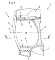
- the support structure 1 of a motor vehicle rear 2 is one Motor vehicle body shown.
- the support structure 1 includes essentially two with respect to the longitudinal center plane 3 mirror symmetry arranged rear side members 4 and 5, which over a rear cross member 6 and a bumper 7 with each other are connected and to the crumple zone in the rear area of the motor vehicle belong.
- the rear side members 4 and 5 of wheel arches 8 and 9 of the rear wheels extend forward to the C-pillar. Downward the side members 4 and 5 are connected to a floor panel 10.
- Each of the longitudinal beams 4 and 5 is made of one length Hollow beams 11 and 12 and from a striking plate 13 and 14 so composed that a closed hollow profile cross section is formed.
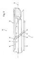
- the hollow carrier 12 of the rear longitudinal carrier designed as an inner shell 5 from two longitudinal sections 15 and 16 along one extending obliquely to the central longitudinal axis 17 of the hollow support 12 Joining level 18 composed.
- the equivalent is the Hollow beam 11 of the longitudinal beam 4 constructed.
- the longitudinal beam 5 can in a known manner with predetermined bending points be provided to energy in the event of a rear impact to absorb.
- connection length between the Lengths 15 and 16 lengthened and thus the connection intensity.
- Load forces for example in the event of a rear impact, the force is distributed in the inclined joining plane, so that an even load distribution is achieved on the interface than when perpendicular to the central longitudinal axis 17 extending joining plane.
- With the extension of the connection length can also buckle the side member in the area decelerate the joining plane or due to the inclination of the joining plane Stabilize from the back up to the front down.
Landscapes
- Engineering & Computer Science (AREA)
- Chemical & Material Sciences (AREA)
- Combustion & Propulsion (AREA)
- Transportation (AREA)
- Mechanical Engineering (AREA)
- Body Structure For Vehicles (AREA)
Abstract
Description
- Fig. 1
- eine Übersichtsdarstellung eines Kraftwagenhecks in einer Ansicht schräg von oben,
- Fig. 2
- eine Schnittdarstellung gemäß der Linie II-II in Fig. 1 sowie
- Fig. 3
- eine Einzeldarstellung des zusammengesetzten Längsträgers in einer Ansicht schräg von der Seite.
Claims (9)
- Tragstruktur einer selbsttragenden Karosserie mit mindestens einem aus zwei Längenabschnitten gefügten Hohlträger, dessen Längenabschnitte im Bereich einer quer zur Hohlträgerlängsachse verlaufenden Fügeebene miteinander verbunden sind, wobei die Endbereiche der Längenabschnitte einander überlappend gefügt sind,
dadurch gekennzeichnet, daß die einander überlappenden Endbereiche (19, 20) der Längenabschnitte (15, 16) schräg zur Mittellängsachse (17) des Hohlträgers (12) im Fügebereich verlaufen. - Tragstruktur nach Anspruch 1,
dadurch gekennzeichnet, daß der Hohlträger (11, 12) eine Teilschale eines aus mehreren Teilschalen zusammengesetzten Längsträgers (4, 5) ist, bei dem die Fügeebene (18) in einem zu einer Knautschzone der Karosserie gehörenden Längenbereich angeordnet ist. - Tragstruktur nach Anspruch 2,
dadurch gekennzeichnet, daß die Fügeebene (18) unter einem Winkel zwischen 15° und 75° geneigt zur Mittellängsachse (17) des Hohlträgers (12) im Bereich der Fügeebene (18) verläuft. - Tragstruktur nach Anspruch 3,
dadurch gekennzeichnet, daß der Längsträger (4, 5) im Bodenbereich des Kraftwagenhecks (2) angeordnet ist, wobei die Fügeebene (18) von hinten oben nach vorn unten geneigt verläuft. - Tragstruktur nach Anspruch 1,
dadurch gekennzeichnet, daß einer der Endbereiche (19) unter Anpassung an den Hohlquerschnitt des anderen Endbereichs (20) verjüngt ist. - Tragstruktur nach Anspruch 5,
dadurch gekennzeichnet, daß die Endbereiche (19, 20) der Längenabschnitte (15, 16) durch Punktschweißen miteinander verbunden sind. - Tragstruktur nach Anspruch 1,
dadurch gekennzeichnet, daß die Längenabschnitte (15, 16) des Hohlträgers (12) einen einseitig offenen u-förmigen Querschnitt aufweisen. - Tragstruktur nach Anspruch 7,
dadurch gekennzeichnet, daß die offene Seite der zum Hohlträger (12) verbundenen Längenabschnitte (15, 16) mit einem Schließblech (14) geschlossen ist. - Tragstruktur nach Anspruch 1,
dadurch gekennzeichnet, daß die Längenabschnitte (15, 16) des Hohlträgers (12) einen umlaufend geschlossenen Hohlprofilquerschnitt aufweisen.
Applications Claiming Priority (2)
| Application Number | Priority Date | Filing Date | Title |
|---|---|---|---|
| DE10061848 | 2000-12-12 | ||
| DE10061848A DE10061848A1 (de) | 2000-12-12 | 2000-12-12 | Tragstruktur einer selbsttragenden Karosserie |
Publications (2)
| Publication Number | Publication Date |
|---|---|
| EP1215106A2 true EP1215106A2 (de) | 2002-06-19 |
| EP1215106A3 EP1215106A3 (de) | 2004-01-07 |
Family
ID=7666818
Family Applications (1)
| Application Number | Title | Priority Date | Filing Date |
|---|---|---|---|
| EP01127631A Withdrawn EP1215106A3 (de) | 2000-12-12 | 2001-11-20 | Tragstruktur einer selbsttragender Karosserie |
Country Status (3)
| Country | Link |
|---|---|
| US (1) | US6578908B2 (de) |
| EP (1) | EP1215106A3 (de) |
| DE (1) | DE10061848A1 (de) |
Cited By (1)
| Publication number | Priority date | Publication date | Assignee | Title |
|---|---|---|---|---|
| WO2004024539A1 (de) * | 2002-08-27 | 2004-03-25 | Daimlerchrysler Ag | Karosserie mit einer tragstruktur aus zusammengesetzten teilmodulen |
Families Citing this family (4)
| Publication number | Priority date | Publication date | Assignee | Title |
|---|---|---|---|---|
| DE10232844B4 (de) * | 2002-07-19 | 2015-10-01 | Volkswagen Ag | Bodenlängsträgeranordnung an Kraftfahrzeugen |
| AT412550B (de) | 2003-06-24 | 2005-04-25 | Voestalpine Stahl Gmbh | Träger für eine fahrzeugkarosserie |
| WO2018115598A1 (fr) * | 2016-12-20 | 2018-06-28 | Psa Automobiles S.A. | Longeronnet pour une structure arrière de châssis de véhicule et véhicule comprenant une telle structure |
| JP6888522B2 (ja) * | 2017-11-02 | 2021-06-16 | トヨタ自動車株式会社 | 車体フレーム構造 |
Family Cites Families (11)
| Publication number | Priority date | Publication date | Assignee | Title |
|---|---|---|---|---|
| SE463555B (sv) * | 1989-04-28 | 1990-12-10 | Volvo Ab | Anordning vid ihaaliga balkar i en bilkaross |
| JP2717860B2 (ja) * | 1989-07-31 | 1998-02-25 | ダイハツ工業株式会社 | 車体サイドメンバの連結部構造 |
| JP2563632Y2 (ja) * | 1990-11-29 | 1998-02-25 | マツダ株式会社 | 自動車の前部車体構造 |
| JP2979763B2 (ja) * | 1991-09-05 | 1999-11-15 | トヨタ自動車株式会社 | 車両のフレーム構造 |
| JPH05319308A (ja) * | 1992-05-14 | 1993-12-03 | Mazda Motor Corp | 自動車の前部車体構造及びその組立方法 |
| US5419609A (en) * | 1993-01-07 | 1995-05-30 | Ford Motor Company | Energy isolation apparatus for an automotive vehicle |
| JP3357201B2 (ja) * | 1994-10-19 | 2002-12-16 | 本田技研工業株式会社 | 自動車の車体前部構造 |
| US5913565A (en) * | 1995-09-22 | 1999-06-22 | Nissan Motor | Vehicle member |
| US6010155A (en) * | 1996-12-31 | 2000-01-04 | Dana Corporation | Vehicle frame assembly and method for manufacturing same |
| US6099194A (en) * | 1997-08-20 | 2000-08-08 | Dana Corporation | Splice joint for connecting adjacent side rail sections in a vehicle body and frame assembly |
| JP3965230B2 (ja) * | 1997-08-29 | 2007-08-29 | プレス工業株式会社 | シャシーフレーム用サイドメンバーおよびその製造方法 |
-
2000
- 2000-12-12 DE DE10061848A patent/DE10061848A1/de not_active Withdrawn
-
2001
- 2001-11-20 EP EP01127631A patent/EP1215106A3/de not_active Withdrawn
- 2001-12-07 US US10/013,122 patent/US6578908B2/en not_active Expired - Fee Related
Non-Patent Citations (1)
| Title |
|---|
| None |
Cited By (1)
| Publication number | Priority date | Publication date | Assignee | Title |
|---|---|---|---|---|
| WO2004024539A1 (de) * | 2002-08-27 | 2004-03-25 | Daimlerchrysler Ag | Karosserie mit einer tragstruktur aus zusammengesetzten teilmodulen |
Also Published As
| Publication number | Publication date |
|---|---|
| US6578908B2 (en) | 2003-06-17 |
| EP1215106A3 (de) | 2004-01-07 |
| DE10061848A1 (de) | 2002-06-13 |
| US20020079722A1 (en) | 2002-06-27 |
Similar Documents
| Publication | Publication Date | Title |
|---|---|---|
| EP1525132B1 (de) | Bodenträgeranordnung an kraftfahrzeugen | |
| DE10040824B4 (de) | Lenksäulen-Tragbalkenstruktur | |
| DE10108287B4 (de) | Karosseriestruktur | |
| DE69719744T2 (de) | Modularer fahrzeugrahmen | |
| DE102015215655B4 (de) | Fahrzeugkarosserie | |
| EP1534578B1 (de) | Karosserie mit einer tragstruktur aus zusammengesetzten teilmodulen | |
| DE102015205166B4 (de) | Fahrzeugkarosserie | |
| EP1840003B1 (de) | Schwellerverstärkungselement für eine Fahrzeugkarosserie | |
| DE102010026707B4 (de) | Vorrichtung, insbesondere am Vorbau eines Kraftfahrzeuges | |
| WO2012007346A1 (de) | B-säulenverstärkung eines kraftfahrzeugs | |
| DE102007042292A1 (de) | Plastisch verformbare Doppelzellenverbindung für die Front von Automobilen | |
| DE102010051256A1 (de) | Kraftfahrzeugkarosserie mit Verstärkungsstruktur | |
| DE102010041184A1 (de) | Karosseriestruktur für einen Frontbereich eines Fahrzeugs | |
| DE102018100701A1 (de) | Dachrahmen mit einer Strebe zum Verstärken gewölbter Elemente | |
| DE102011053246A1 (de) | Karosserie und Fahrzeug | |
| DE102016216317A1 (de) | Stoßfängerquerträger | |
| EP1525133B1 (de) | Bodenversteifungsstruktur an kraftfahrzeugen | |
| WO2020216602A1 (de) | Karosserie-vorbaustruktur für ein fahrzeug | |
| DE102020112125B3 (de) | Baugruppe für ein Fahrzeug | |
| WO2021255042A1 (de) | Hohlkammerträgerbaugruppe für ein fahrzeug | |
| DE102021101094A1 (de) | Fahrzeugkarosserie eines Personenkraftwagens mit Unterflurbatterie | |
| EP1361140A2 (de) | Karosserie für ein Kraftfahrzeug | |
| EP0896919A2 (de) | Querträger zur Halterung der Lenksäule eines Kraftfahrzeuges, insbesondere eines Personenkraftwagens | |
| DE102019218697A1 (de) | Kraftfahrzeugkarosserie mit einem Stützelement und Kraftfahrzeug, umfassend die Fahrzeugkarosserie | |
| DE10061848A1 (de) | Tragstruktur einer selbsttragenden Karosserie |
Legal Events
| Date | Code | Title | Description |
|---|---|---|---|
| PUAI | Public reference made under article 153(3) epc to a published international application that has entered the european phase |
Free format text: ORIGINAL CODE: 0009012 |
|
| AK | Designated contracting states |
Kind code of ref document: A2 Designated state(s): AT BE CH CY DE DK ES FI FR GB GR IE IT LI LU MC NL PT SE TR |
|
| AX | Request for extension of the european patent |
Free format text: AL;LT;LV;MK;RO;SI |
|
| PUAL | Search report despatched |
Free format text: ORIGINAL CODE: 0009013 |
|
| AK | Designated contracting states |
Kind code of ref document: A3 Designated state(s): AT BE CH CY DE DK ES FI FR GB GR IE IT LI LU MC NL PT SE TR |
|
| AX | Request for extension of the european patent |
Extension state: AL LT LV MK RO SI |
|
| 17P | Request for examination filed |
Effective date: 20031219 |
|
| 17Q | First examination report despatched |
Effective date: 20040331 |
|
| STAA | Information on the status of an ep patent application or granted ep patent |
Free format text: STATUS: THE APPLICATION HAS BEEN WITHDRAWN |
|
| AKX | Designation fees paid |
Designated state(s): DE FR GB IT SE |
|
| 18W | Application withdrawn |
Effective date: 20040830 |