EP1215065B1 - Method of assembling a door - Google Patents
Method of assembling a door Download PDFInfo
- Publication number
- EP1215065B1 EP1215065B1 EP01310275A EP01310275A EP1215065B1 EP 1215065 B1 EP1215065 B1 EP 1215065B1 EP 01310275 A EP01310275 A EP 01310275A EP 01310275 A EP01310275 A EP 01310275A EP 1215065 B1 EP1215065 B1 EP 1215065B1
- Authority
- EP
- European Patent Office
- Prior art keywords
- door
- assembling
- assembly
- panel
- window regulator
- Prior art date
- Legal status (The legal status is an assumption and is not a legal conclusion. Google has not performed a legal analysis and makes no representation as to the accuracy of the status listed.)
- Expired - Lifetime
Links
- 238000000034 method Methods 0.000 title claims description 28
- 230000004888 barrier function Effects 0.000 claims description 2
- 230000006378 damage Effects 0.000 description 7
- 208000027418 Wounds and injury Diseases 0.000 description 6
- 239000005357 flat glass Substances 0.000 description 6
- 230000002787 reinforcement Effects 0.000 description 6
- 239000003973 paint Substances 0.000 description 5
- 239000000853 adhesive Substances 0.000 description 4
- 230000001070 adhesive effect Effects 0.000 description 4
- 238000003825 pressing Methods 0.000 description 4
- 210000003660 reticulum Anatomy 0.000 description 4
- 238000003466 welding Methods 0.000 description 4
- 239000011521 glass Substances 0.000 description 3
- 230000001066 destructive effect Effects 0.000 description 2
- 230000007246 mechanism Effects 0.000 description 2
- 206010039203 Road traffic accident Diseases 0.000 description 1
- 238000004026 adhesive bonding Methods 0.000 description 1
- 238000009957 hemming Methods 0.000 description 1
- 239000012528 membrane Substances 0.000 description 1
- 230000007935 neutral effect Effects 0.000 description 1
- 238000010422 painting Methods 0.000 description 1
- 230000008569 process Effects 0.000 description 1
- 230000002250 progressing effect Effects 0.000 description 1
- 230000008439 repair process Effects 0.000 description 1
- 238000005728 strengthening Methods 0.000 description 1
- XLYOFNOQVPJJNP-UHFFFAOYSA-N water Substances O XLYOFNOQVPJJNP-UHFFFAOYSA-N 0.000 description 1
Images



Classifications
-
- B—PERFORMING OPERATIONS; TRANSPORTING
- B60—VEHICLES IN GENERAL
- B60J—WINDOWS, WINDSCREENS, NON-FIXED ROOFS, DOORS, OR SIMILAR DEVICES FOR VEHICLES; REMOVABLE EXTERNAL PROTECTIVE COVERINGS SPECIALLY ADAPTED FOR VEHICLES
- B60J5/00—Doors
- B60J5/04—Doors arranged at the vehicle sides
- B60J5/0412—Lower door structure
- B60J5/0413—Inner panel, e.g. characterised by carrying components
-
- B—PERFORMING OPERATIONS; TRANSPORTING
- B60—VEHICLES IN GENERAL
- B60J—WINDOWS, WINDSCREENS, NON-FIXED ROOFS, DOORS, OR SIMILAR DEVICES FOR VEHICLES; REMOVABLE EXTERNAL PROTECTIVE COVERINGS SPECIALLY ADAPTED FOR VEHICLES
- B60J5/00—Doors
- B60J5/04—Doors arranged at the vehicle sides
- B60J5/0401—Upper door structure
- B60J5/0405—Inboard or outboard side of window frame formed integrally with the lower door structure
-
- B—PERFORMING OPERATIONS; TRANSPORTING
- B60—VEHICLES IN GENERAL
- B60J—WINDOWS, WINDSCREENS, NON-FIXED ROOFS, DOORS, OR SIMILAR DEVICES FOR VEHICLES; REMOVABLE EXTERNAL PROTECTIVE COVERINGS SPECIALLY ADAPTED FOR VEHICLES
- B60J5/00—Doors
- B60J5/04—Doors arranged at the vehicle sides
- B60J5/0463—Conceptual assembling of door, i.e. how door frame parts should be fitted together to form door
-
- Y—GENERAL TAGGING OF NEW TECHNOLOGICAL DEVELOPMENTS; GENERAL TAGGING OF CROSS-SECTIONAL TECHNOLOGIES SPANNING OVER SEVERAL SECTIONS OF THE IPC; TECHNICAL SUBJECTS COVERED BY FORMER USPC CROSS-REFERENCE ART COLLECTIONS [XRACs] AND DIGESTS
- Y10—TECHNICAL SUBJECTS COVERED BY FORMER USPC
- Y10T—TECHNICAL SUBJECTS COVERED BY FORMER US CLASSIFICATION
- Y10T29/00—Metal working
- Y10T29/49—Method of mechanical manufacture
- Y10T29/49616—Structural member making
- Y10T29/49622—Vehicular structural member making
-
- Y—GENERAL TAGGING OF NEW TECHNOLOGICAL DEVELOPMENTS; GENERAL TAGGING OF CROSS-SECTIONAL TECHNOLOGIES SPANNING OVER SEVERAL SECTIONS OF THE IPC; TECHNICAL SUBJECTS COVERED BY FORMER USPC CROSS-REFERENCE ART COLLECTIONS [XRACs] AND DIGESTS
- Y10—TECHNICAL SUBJECTS COVERED BY FORMER USPC
- Y10T—TECHNICAL SUBJECTS COVERED BY FORMER US CLASSIFICATION
- Y10T29/00—Metal working
- Y10T29/49—Method of mechanical manufacture
- Y10T29/49826—Assembling or joining
- Y10T29/49828—Progressively advancing of work assembly station or assembled portion of work
- Y10T29/49829—Advancing work to successive stations [i.e., assembly line]
-
- Y—GENERAL TAGGING OF NEW TECHNOLOGICAL DEVELOPMENTS; GENERAL TAGGING OF CROSS-SECTIONAL TECHNOLOGIES SPANNING OVER SEVERAL SECTIONS OF THE IPC; TECHNICAL SUBJECTS COVERED BY FORMER USPC CROSS-REFERENCE ART COLLECTIONS [XRACs] AND DIGESTS
- Y10—TECHNICAL SUBJECTS COVERED BY FORMER USPC
- Y10T—TECHNICAL SUBJECTS COVERED BY FORMER US CLASSIFICATION
- Y10T29/00—Metal working
- Y10T29/49—Method of mechanical manufacture
- Y10T29/49826—Assembling or joining
- Y10T29/4984—Retaining clearance for motion between assembled parts
-
- Y—GENERAL TAGGING OF NEW TECHNOLOGICAL DEVELOPMENTS; GENERAL TAGGING OF CROSS-SECTIONAL TECHNOLOGIES SPANNING OVER SEVERAL SECTIONS OF THE IPC; TECHNICAL SUBJECTS COVERED BY FORMER USPC CROSS-REFERENCE ART COLLECTIONS [XRACs] AND DIGESTS
- Y10—TECHNICAL SUBJECTS COVERED BY FORMER USPC
- Y10T—TECHNICAL SUBJECTS COVERED BY FORMER US CLASSIFICATION
- Y10T29/00—Metal working
- Y10T29/49—Method of mechanical manufacture
- Y10T29/49826—Assembling or joining
- Y10T29/49885—Assembling or joining with coating before or during assembling
-
- Y—GENERAL TAGGING OF NEW TECHNOLOGICAL DEVELOPMENTS; GENERAL TAGGING OF CROSS-SECTIONAL TECHNOLOGIES SPANNING OVER SEVERAL SECTIONS OF THE IPC; TECHNICAL SUBJECTS COVERED BY FORMER USPC CROSS-REFERENCE ART COLLECTIONS [XRACs] AND DIGESTS
- Y10—TECHNICAL SUBJECTS COVERED BY FORMER USPC
- Y10T—TECHNICAL SUBJECTS COVERED BY FORMER US CLASSIFICATION
- Y10T29/00—Metal working
- Y10T29/49—Method of mechanical manufacture
- Y10T29/49826—Assembling or joining
- Y10T29/49904—Assembling a subassembly, then assembling with a second subassembly
Definitions
- the present invention relates to a method of assembling a door and a method of assembling a vehicle including a door.
- the invention relates to a method of assembling a car (automobile) door.
- Known car doors are typically assembled by welding various strengthening and reinforcement elements to an inner panel and then attaching an outer panel to this subassembly by a hemming technique.
- This bare door is then allocated to a car body along with other bare doors and a bare bonnet and a bare boot and this set of components is then painted together to provide the final exterior colour for the vehicle.
- Such a technique ensures that all exterior surfaces of the vehicle are of uniform colour since the final coat of paint on all panels is from the same batch of paint.
- the functional hardware is then installed through holes in the inner panel into the painted doors and water management membrane is applied to this inner panel to close the various access holes.
- a trim panel is fixed to the inner panel to provide a styled aesthetically pleasing surface which incorporates appropriate features such as switches, door pockets, loudspeakers and heater grills.
- US 4845894 (Herringshaw et al) discloses a method of assembling a door outer panel to a door inner panel in which an anti-intrusion beam is the first component to be fitted to an outer face of the inner panel, followed by various functional components, and finally by the outer panel.
- US 4845894 further discloses a vehicle assembly procedure in which a vehicle is painted together with a door outer panel. A pre-assembled door module comprising a window regulator and latching hardware is then attached to the vehicle. The painted outer panel is then attached to the door module.
- DE 3402135 A1 (Brose) discloses a vehicle door having a carrier plate with an outer face to which a longitudinal beam and one part of a window regulator mechanism may be secured, and an inner face to which a second part of a window regulator mechanism and door inner panel may be secured.
- An object of the present invention is provide improved method of assembling a door.
- this allows for the majority of the door components to be assembled onto the door (in particular at a door assembly line) prior to a door outer panel being secured to the door.
- a door 30 in this case a front left hand door of a car (automobile).
- the door is assembled from various components including a door inner panel 31, a window regulator assembly 34 a combined anti intrusion beam and waist reinforcement beam component 36 and a door outer panel 38.
- Inner panel 31 is in the form of a pressing having an outer face 40 which faces outwardly relative to an associated vehicle and an inner face 41 which faces inwardly relative to an associated vehicle.
- Door inner panel 31 includes an upper window frame 42 and a lower portion 43 which together define a window aperture 44.
- the door inner panel 31 includes various fixing holes 45 a window regulator motor aperture 46, a loud speaker aperture 47, latch fixing holes 48, holes 49 and inside door release handle 50.
- the inner panel will include reinforcement (not shown) adjacent to front hinge points and also in the region of the latch.
- a window regulator assembly 34 the components of which are shown in figure 2 is assembled as a subassembly and this subassembly is then assembled towards the outer face 40 of the door inner panel 31 in the direction of arrow A.
- a window regulator carrier 1 is provided as a chassis or frame on which is mounted further components of the window regulator assembly.
- the carrier 1 is in the form of a pressing and includes a 'X' shaped portion having arms 52A, 52B, 52C and 52D which meet at a central region 53. Ends of arms 52A and 52B remote from central region 53 are connected by a substantially vertical portion 54 of the carrier 1. Similarly ends of arms 52C and 52D remote from the central region 53 are also connected by a substantially vertical portion 55.
- Arms 52A, 52B, 52C and 52D are all generally elongate and U shaped in cross section as a result of the pressing process.
- Carrier 1 includes holes 56 for mounting of the carrier, via fixing means which pass through hole 56 and through corresponding holes 45.
- Carrier 1 further includes holes 57 for mounting of cable guides in the form of pulley wheels 4 via rivets 5.
- Carrier 1 further includes mounting plate 57 upon which is mounted flexible latch support 18, mounting plate 58 upon which is mounted inner release handle assembly 19, and window regulator drive means plate in the form of a window regulator motor plate 59.
- Motor plate 59 is generally planar in shape and is larger than window regulator motor aperture 46 so that seal 15 can provide for a moisture barrier between the interior of the door and the interior of the vehicle.
- Motor plate 59 includes a cable drum housing 60.
- Front rail 2 and rear rail 3 are mountable in spaced generally parallel relationship on portions 55 and 56 of carrier 1 respectively and guide cursors 13 and 14.
- front and rear rails could be integral with the carrier.
- Two cable tensioner 6 and a bare cable separator 7 are also mounted on the carrier and will be further described below.
- Window regulator motor 16 is mounted on motor plate 59 via fixing screws 17.
- Latch assembly 20 is mounted on flexible latch support 18 which allows for slight adjustment in the position of latch assembly 20 relative to carrier 1 when the window regulator assembly is assembled into the door inner panel.
- An inner release handle cable 21 connects inner release handle assembly 19 to latch assembly 20.
- a sill button link rod 22 is connected to latch assembly 20 at one end and at another end is connected to a sill button 23.
- An outer handle connection 29 operably connects the outer door handle with the latch assembly once the handle has been fitted.
- a latch security shield 26 is provided above the latch assembly 20 to prevent unauthorised entry to the vehicle by the use of a 'slim Jim'.
- a wiring harness 24 connects various electrical components of the window regulator assembly to the main wire harness of the vehicle (not shown).
- the four pulley wheels 4 have been labelled as a first upper (1U), a first lower (1L), a second upper (2U) and a second lower (2L).
- a bare cable assembly 62 is provided and includes a lower cable 11 which connects cable drum 8 to the front cursor 13, an upper cable 10 which connects the cable drum 8 to the rear cursor 14, and an intermediate cable 12 which connects the front cursor 13 to the rear cursor 14.
- One end of lower cable 11 is wound around the threaded exterior of drum 8 and secured thereto.
- One end of cable drum 10 is also wound around a different portion of the threaded exterior of cable drum 10 and secured thereto.
- Window glass assembly 25 includes fixings for securing the lower edge thereof to the front and rear cursors 13 and 14.
- drum 8 is mounted on bush 9 in driving connection with motor 16.
- the upper cable 10, lower cable 11 and intermediate cable 12 define a cable path which runs between the various pulley wheels 4 and includes a first cable path portion connecting the first upper cable guide to the first lower cable guide, a second cable path portion connecting the second upper cable guide to the second lower cable guide, a first further cable path portion connecting the first upper cable guide to the second lower cable guide and a second further cable path portion connecting the first lower cable guide to the second upper cable guide.
- the first and second cable path portions are substantially vertical and are substantially parallel to the front and rear rails 2 and 3 which define the direction of vertical movement of the window glass 25.
- the first further portion and second further portion together form a 'X' shape.
- the second further portion is defined by the portion of the lower cable 11 running between the first lower cable guide and the drum (but not around the drum) in combination with that portion of the upper cable 10 running between the second upper cable guide and the drum (though not around the drum).
- the cable arrangement is a bare cable arrangement
- arms 52A, 52B, 52C and 52D extend to at least the mounting point of the pulley wheels 4 as do portions 54 and 55, then the carrier forms a triangulated structure at each of the pulley wheels where the tension in the cables 10, 11 and 12 is reacted.
- first further and second further cable path portions cross and further in view of the fact that as cable drum 8 rotates and that portion of cable 10 which is being wound onto or off from the cable drum moves laterally relative to the door then it can be seen that advantageously a bare cable separator 7 can be mounted at the central region 3 of the carrier 1 in order to guide cable 10 past cable 12 to ensure that they do not 'saw' against each during to the raising and lowering of the window glass 5.
- the components as shown in figure 2 can all be pre assembled to form the window regulator assembly 34.
- Component 36 is formed as a single pressing and includes an anti intrusion beam 64 designed to prevent intrusion into the vehicle of parts of other vehicles and the like in the event of a road traffic accident.
- the component 36 further includes a waist level reinforcement beam which in use supports the upper edge 38A of door outer panel 38 the other edges of door outer panel 38 being supported by the door inner panel.
- the component 36 includes fixing holes 65 which co-operate with holes 49 and fixings 66 to secure the component 36 to the inner panel 31.
- One method of assembling the door 30 is as follows:-
- Inner panel 31 is placed horizontally on a jig such that inner face 41 faces downwards and outer face 40 faces upwards (through the door need not be assembled 'horizontally').
- the inner waist line seal 69 and glass run 70 are moved to position (see arrows B and C) and secured on the door inner panel 31 at the periphery of the window aperture 44.
- Loudspeaker 71 is moved to position (see arrow D) and is secured to the door inner panel 31 by four screws 72 which are tightened by the assembly operator from above i.e. in a direction facing the outer face 40 (when on the jig faces upwards).
- the window regulator assembly 34 is then moved to position in the direction of arrow A and secured in place by screws (not shown) which are screwed into holes 45 from above.
- the component 36 is then moved to position in the direction of arrow E and fixings 66 are used to secure it to the door inner panel (as described above).
- Outer waist line seal 73 is mounted on upper edge 38A of outer panel 38 and this subassembly is then moved in the direction of arrow F and is secured to the door inner panel 31.
- FIGS 4 to 6 show the manner in which the door is assembled.
- Figure 7 shows a further embodiment of a vehicle door made according to the present invention, in which articles which perform substantially the same function as those in figures 1 to 6 are labelled 100 greater.
- this embodiment shows a rear vehicle door.
- Various fixings can be used to secure the various components.
- Bolts and screws and other similar threaded fasteners have an assembled axis e.g. the longitudinal axis of the bolt or screw. Furthermore they have an assembly direction defined by the bolt head or screw head. Thus the assembly direction of a screw is from the screw head to the screw point. Thus were such fixings are used the assembly direction can be towards the outer face 40 i.e. inwardly relative to the associated vehicle.
- Typical known vehicle doors include fixings having assembly directions which are orientated outwardly relative to the vehicle.
- bolts and screws are releasable fixing means.
- An alternative fixing means which can be used is a pop rivet which also has an assembly axis and an assembly direction.
- Alternative fixing means include adhesive bonding of one component to another or alternatively welding of one component to another.
- bolts and screws are generally removable so that components being secured by the bolts or screws can be separated without damage to either component. Furthermore pop rivets can be drilled out in order to separate two components again without damage to either component.
- the adhesive bond between two components can be broken without damage to either component.
- welding of one component to another component provides a fixing means which prevents the components being separated without damage to one or other component
- welding techniques generate extreme amounts of heat and hence this is not a fixing technique which is suitable for refixing a component within a partially assembled door.
- the fixing means used to secure the various door components allows the various door components to be non destructively separated and also reconnected.
- non destructive separating of components refers to the non destruction of the components per se and not to be the non destruction of the fixing means.
- components fixed by an adhesive joint can be non destructively separated without damage to either component whilst nevertheless destroying the adhesive per se. Under these circumstances new adhesive has to be used to reconnect the two components.
- the component 36 can be formed as a subassembly from an anti intrusion beam and a waist level reinforcement beam. As such in the event that just the anti intrusion beam is damaged then it can be replaced independently of the waist level reinforcement beam and vice versa.
- loudspeaker 71 is secured by dedicated screws 72, that as to say screws 72 secure only loudspeaker 71.
- component 36 is secured by dedicated fixings 66.
- window regulator assembly 34 is also secured by dedicated screws (not shown).
- a particular fixing means may be utilised to secure two components.
- a loud speaker could be secured by three of the four screws 72 with the fourth screw being utilised to secure both the part of the window regulator assembly 34 and a part of the loud speaker 71.
- a car manufacturer is typically supplied with various car components by component suppliers.
- the components themselves can be individual items (such as nuts or bolts) or alternatively they can be subassemblies such as engines, gearboxes, axles, bonnets (hoods), boot lids (trunk lids), body shells or doors.
- the major exterior coloured surface of the door 30 is the exterior surface of the door outer panel 38. It is possible to paint the exterior surface of the upper window frame in a neutral colour, such a black, without significantly affecting the exterior aesthetic appearance of the vehicle as a whole.
- a neutral colour such as black
- the door outer panel can be provided at the car manufacturers assembly line (also known herein as a second assembly line) wherein it can be allocated to a specific car body shell along with other doors and a bonnet and boot. This set of components can then all be painted simultaneously with paint from the same batch to ensure uniform colour.
- car manufacturers assembly line also known herein as a second assembly line
- the door assembly 76 can then be transported from the door assembly line to the vehicle assembly line where the outer panel can be assembled onto the door and the door can be assembled onto the associated vehicle. Note that the order in which the door outer skin is assembled on to the door and the door is assembled onto the associated vehicle can be carried out in either order.
- the door assembly 76 can have various levels of equipment e.g. with or without loudspeaker, with a window regulator motor or with a manual window regulator winder, with a manual only latch arrangement or with a electronic central door locking latch arrangement.
- door outer panel at the vehicle assembly line most notably outer panels of differing colour e.g. red, green and blue but also outer panels of differing shapes for fitment onto different car models having a substantially common floor pan.
Landscapes
- Engineering & Computer Science (AREA)
- Mechanical Engineering (AREA)
- Automobile Manufacture Line, Endless Track Vehicle, Trailer (AREA)
- Window Of Vehicle (AREA)
Description
- The present invention relates to a method of assembling a door and a method of assembling a vehicle including a door. In particular the invention relates to a method of assembling a car (automobile) door.
- Known car doors are typically assembled by welding various strengthening and reinforcement elements to an inner panel and then attaching an outer panel to this subassembly by a hemming technique. This bare door is then allocated to a car body along with other bare doors and a bare bonnet and a bare boot and this set of components is then painted together to provide the final exterior colour for the vehicle. Such a technique ensures that all exterior surfaces of the vehicle are of uniform colour since the final coat of paint on all panels is from the same batch of paint.
- Subsequently the functional hardware is then installed through holes in the inner panel into the painted doors and water management membrane is applied to this inner panel to close the various access holes.
- Finally, a trim panel is fixed to the inner panel to provide a styled aesthetically pleasing surface which incorporates appropriate features such as switches, door pockets, loudspeakers and heater grills.
- Thus the assembly of the door components into the door is from the inside (when considering the associated vehicle). Such an assembly method means that the various door components must be assembled into the door on the vehicle assembly line since:-
- a) all exterior panels are painted together and
- b) the door components must be assembled after painting.
- US 4845894 (Herringshaw et al) discloses a method of assembling a door outer panel to a door inner panel in which an anti-intrusion beam is the first component to be fitted to an outer face of the inner panel, followed by various functional components, and finally by the outer panel. US 4845894 further discloses a vehicle assembly procedure in which a vehicle is painted together with a door outer panel. A pre-assembled door module comprising a window regulator and latching hardware is then attached to the vehicle. The painted outer panel is then attached to the door module.
- DE 3402135 A1 (Brose) discloses a vehicle door having a carrier plate with an outer face to which a longitudinal beam and one part of a window regulator mechanism may be secured, and an inner face to which a second part of a window regulator mechanism and door inner panel may be secured.
- An object of the present invention is provide improved method of assembling a door.
- Thus according to the present invention these is provided a method of assembling of a door comprising the steps of providing: -
- A door inner panel having an outer face and an inner face
- A window regulator assembly comprising a window regulator motor
- An anti intrusion beam
- And a door outer panel,
- Assembling said window regulator assembly on to and towards the outer face prior to, assembling the anti intrusion beam directly towards the outer face prior to assembling the door outer panel towards the outer face, and securing via fixing means the door inner panel, said window regulator assembly, the anti intrusion beam and the door outer panel relative to each other.
- Advantageously this allows for the majority of the door components to be assembled onto the door (in particular at a door assembly line) prior to a door outer panel being secured to the door.
- The invention will now be described, by way of example, with reference to the accompanying drawings in which:-
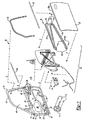
- FIGURE 1 is an exploded view of a door which can be assembled according to the present invention,
- FIGURE 2 is an exploded view of the window regulator components of figure 1,
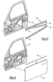
- FIGURES 3 to 6 show one method of assembling the door of figure 1, and
- FIGURE 7 shows a further embodiment of a door which can be assembled according to the present invention.
- With reference to figures 1 and 2 there is shown a
door 30, in this case a front left hand door of a car (automobile). - The door is assembled from various components including a door
inner panel 31, a window regulator assembly 34 a combined anti intrusion beam and waistreinforcement beam component 36 and a doorouter panel 38.Inner panel 31 is in the form of a pressing having anouter face 40 which faces outwardly relative to an associated vehicle and aninner face 41 which faces inwardly relative to an associated vehicle. - Door
inner panel 31 includes anupper window frame 42 and alower portion 43 which together define awindow aperture 44. The doorinner panel 31 includes various fixing holes 45 a window regulator motor aperture 46, aloud speaker aperture 47,latch fixing holes 48,holes 49 and insidedoor release handle 50. Typically the inner panel will include reinforcement (not shown) adjacent to front hinge points and also in the region of the latch. Awindow regulator assembly 34, the components of which are shown in figure 2 is assembled as a subassembly and this subassembly is then assembled towards theouter face 40 of the doorinner panel 31 in the direction of arrow A. - Consideration of figure 2 shows the components of the window regulator assembly in detail. A window regulator carrier 1 is provided as a chassis or frame on which is mounted further components of the window regulator assembly. The carrier 1 is in the form of a pressing and includes a 'X' shaped portion having arms 52A, 52B, 52C and 52D which meet at a
central region 53. Ends of arms 52A and 52B remote fromcentral region 53 are connected by a substantially vertical portion 54 of the carrier 1. Similarly ends of arms 52C and 52D remote from thecentral region 53 are also connected by a substantially vertical portion 55. - Arms 52A, 52B, 52C and 52D are all generally elongate and U shaped in cross section as a result of the pressing process.
- Carrier 1 includes
holes 56 for mounting of the carrier, via fixing means which pass throughhole 56 and throughcorresponding holes 45. - Carrier 1 further includes
holes 57 for mounting of cable guides in the form of pulley wheels 4 via rivets 5. - Carrier 1 further includes
mounting plate 57 upon which is mountedflexible latch support 18,mounting plate 58 upon which is mounted innerrelease handle assembly 19, and window regulator drive means plate in the form of a window regulator motor plate 59. - Motor plate 59 is generally planar in shape and is larger than window regulator motor aperture 46 so that
seal 15 can provide for a moisture barrier between the interior of the door and the interior of the vehicle. - Motor plate 59 includes a cable drum housing 60.
- Front rail 2 and rear rail 3 are mountable in spaced generally parallel relationship on
portions 55 and 56 of carrier 1 respectively and guide cursors 13 and 14. - In further embodiments the front and rear rails could be integral with the carrier.
- Two
cable tensioner 6 and a bare cable separator 7 are also mounted on the carrier and will be further described below. -
Window regulator motor 16 is mounted on motor plate 59 viafixing screws 17. -
Latch assembly 20 is mounted onflexible latch support 18 which allows for slight adjustment in the position oflatch assembly 20 relative to carrier 1 when the window regulator assembly is assembled into the door inner panel. - An inner
release handle cable 21 connects innerrelease handle assembly 19 tolatch assembly 20. - A sill
button link rod 22 is connected tolatch assembly 20 at one end and at another end is connected to asill button 23. - An outer handle connection 29 operably connects the outer door handle with the latch assembly once the handle has been fitted.
- A
latch security shield 26 is provided above thelatch assembly 20 to prevent unauthorised entry to the vehicle by the use of a 'slim Jim'. - A
wiring harness 24 connects various electrical components of the window regulator assembly to the main wire harness of the vehicle (not shown). - For convenience the four pulley wheels 4 have been labelled as a first upper (1U), a first lower (1L), a second upper (2U) and a second lower (2L).
- A
bare cable assembly 62 is provided and includes a lower cable 11 which connects cable drum 8 to the front cursor 13, anupper cable 10 which connects the cable drum 8 to the rear cursor 14, and anintermediate cable 12 which connects the front cursor 13 to the rear cursor 14. - One end of lower cable 11 is wound around the threaded exterior of drum 8 and secured thereto.
- One end of
cable drum 10 is also wound around a different portion of the threaded exterior ofcable drum 10 and secured thereto. -
Window glass assembly 25 includes fixings for securing the lower edge thereof to the front and rear cursors 13 and 14. - In use drum 8 is mounted on bush 9 in driving connection with
motor 16. - Rotation of the drum 8 by the motor in one direction will cause lower cable 11 to be wound onto the drum and
upper cable 10 wound off the drum causing cursors 13 and 14 and hence the window to lower. - Conversely rotation of the drum in the opposite direction by the motor will cause
upper cable 10 to be wound onto the drum and lower cable 11 to be wound off the drum resulting in raising of thewindow glass 25. - It can be seen that the
upper cable 10, lower cable 11 andintermediate cable 12 define a cable path which runs between the various pulley wheels 4 and includes a first cable path portion connecting the first upper cable guide to the first lower cable guide, a second cable path portion connecting the second upper cable guide to the second lower cable guide, a first further cable path portion connecting the first upper cable guide to the second lower cable guide and a second further cable path portion connecting the first lower cable guide to the second upper cable guide. Note that the first and second cable path portions are substantially vertical and are substantially parallel to the front and rear rails 2 and 3 which define the direction of vertical movement of thewindow glass 25. Furthermore the first further portion and second further portion together form a 'X' shape. Note that the second further portion is defined by the portion of the lower cable 11 running between the first lower cable guide and the drum (but not around the drum) in combination with that portion of theupper cable 10 running between the second upper cable guide and the drum (though not around the drum). - In view of the fact that the cable arrangement is a bare cable arrangement, it is necessary to ensure a minimum level of tension in all
cables cables cables - In view of the fact that the first further and second further cable path portions cross and further in view of the fact that as cable drum 8 rotates and that portion of
cable 10 which is being wound onto or off from the cable drum moves laterally relative to the door then it can be seen that advantageously a bare cable separator 7 can be mounted at the central region 3 of the carrier 1 in order to guidecable 10past cable 12 to ensure that they do not 'saw' against each during to the raising and lowering of the window glass 5. - The components as shown in figure 2 can all be pre assembled to form the
window regulator assembly 34. -
Component 36 is formed as a single pressing and includes ananti intrusion beam 64 designed to prevent intrusion into the vehicle of parts of other vehicles and the like in the event of a road traffic accident. - The
component 36 further includes a waist level reinforcement beam which in use supports the upper edge 38A of doorouter panel 38 the other edges of doorouter panel 38 being supported by the door inner panel. - The
component 36 includes fixingholes 65 which co-operate withholes 49 andfixings 66 to secure thecomponent 36 to theinner panel 31. -
Inner panel 31 is placed horizontally on a jig such thatinner face 41 faces downwards andouter face 40 faces upwards (through the door need not be assembled 'horizontally'). - The inner
waist line seal 69 andglass run 70 are moved to position (see arrows B and C) and secured on the doorinner panel 31 at the periphery of thewindow aperture 44. -
Loudspeaker 71 is moved to position (see arrow D) and is secured to the doorinner panel 31 by fourscrews 72 which are tightened by the assembly operator from above i.e. in a direction facing the outer face 40 (when on the jig faces upwards). - The
window regulator assembly 34 is then moved to position in the direction of arrow A and secured in place by screws (not shown) which are screwed intoholes 45 from above. Thecomponent 36 is then moved to position in the direction of arrow E andfixings 66 are used to secure it to the door inner panel (as described above). - Outer
waist line seal 73 is mounted on upper edge 38A ofouter panel 38 and this subassembly is then moved in the direction of arrow F and is secured to the doorinner panel 31. - In particular it should be noted that the various components of the door are assembled from the outside and this is contrary to known assembly methods where such components are assembled into the door from the inside.
- It should also be noted that in view of the motor plate 59 and
seal 15, themotor 16 is on the 'dry' side of the door since any moisture or rain entering the loweringportion 43 of the door via the outerwaist line seal 73 is prevented from progressing through aperture 46 byseal 15. - Figures 4 to 6 show the manner in which the door is assembled.
- Figure 7 shows a further embodiment of a vehicle door made according to the present invention, in which articles which perform substantially the same function as those in figures 1 to 6 are labelled 100 greater.
- In particular this embodiment shows a rear vehicle door.
- Various fixings can be used to secure the various components.
- Bolts and screws and other similar threaded fasteners have an assembled axis e.g. the longitudinal axis of the bolt or screw. Furthermore they have an assembly direction defined by the bolt head or screw head. Thus the assembly direction of a screw is from the screw head to the screw point. Thus were such fixings are used the assembly direction can be towards the
outer face 40 i.e. inwardly relative to the associated vehicle. - Typically known vehicle doors include fixings having assembly directions which are orientated outwardly relative to the vehicle.
- In particular bolts and screws are releasable fixing means.
- An alternative fixing means which can be used is a pop rivet which also has an assembly axis and an assembly direction.
- Alternative fixing means include adhesive bonding of one component to another or alternatively welding of one component to another.
- Furthermore a known method of securing an outer panel to an inner panel is to 'hem' the edge of the outer panel i.e. to deform it around the corresponding edge of the inner panel.
- It should be noted that bolts and screws are generally removable so that components being secured by the bolts or screws can be separated without damage to either component. Furthermore pop rivets can be drilled out in order to separate two components again without damage to either component.
- Depending upon the design, the adhesive bond between two components can be broken without damage to either component.
- However, welding of one component to another component provides a fixing means which prevents the components being separated without damage to one or other component Furthermore where components are welded together, such welding techniques generate extreme amounts of heat and hence this is not a fixing technique which is suitable for refixing a component within a partially assembled door.
- Similarly where an outer panel has been hemmed onto an inner panel it is not possible to break the hemmed joint without damaging the outer panel such that it can no longer be reused. Advantageously the fixing means used to secure the various door components allows the various door components to be non destructively separated and also reconnected.
- It should be noted that the non destructive separating of components as mentioned herein refers to the non destruction of the components per se and not to be the non destruction of the fixing means. Thus components fixed by an adhesive joint can be non destructively separated without damage to either component whilst nevertheless destroying the adhesive per se. Under these circumstances new adhesive has to be used to reconnect the two components.
- Where the
door 30 has been assembled using non destructive type fixing means then it is possible to:- - a) remove a damaged outer panel and replace with a new outer panel,
- b) remove both a damaged outer panel and a damaged
component 36 and replace with anew component 36 and new outer panel, - c) remove an undamaged outer panel and remove an
undamaged component 36 in order to gain access and repair other components of the door such as the window regulator assembly (and in particular replace a broken window glass), replace a damaged loudspeaker, or replace a damaged latch. - In further embodiments the
component 36 can be formed as a subassembly from an anti intrusion beam and a waist level reinforcement beam. As such in the event that just the anti intrusion beam is damaged then it can be replaced independently of the waist level reinforcement beam and vice versa. - It should be noted that
loudspeaker 71 is secured bydedicated screws 72, that as to sayscrews 72 secure onlyloudspeaker 71. Similarlycomponent 36 is secured bydedicated fixings 66. Similarlywindow regulator assembly 34 is also secured by dedicated screws (not shown). - In further embodiments a particular fixing means may be utilised to secure two components. Thus, for example, where the space between the aperture 46 and the
aperture 47 is a limited, a loud speaker could be secured by three of the fourscrews 72 with the fourth screw being utilised to secure both the part of thewindow regulator assembly 34 and a part of theloud speaker 71. Thus it can be seen that, depending upon the embodiment, various components can be assembled into place, whilst not being fully secured in place. The full securement in place only being possible once a further component has been added. - A car manufacturer is typically supplied with various car components by component suppliers. The components themselves can be individual items (such as nuts or bolts) or alternatively they can be subassemblies such as engines, gearboxes, axles, bonnets (hoods), boot lids (trunk lids), body shells or doors.
- With regards to body shells, bonnets, boots and doors, it is important that the exterior surfaces of these components, of a particular vehicle are all painted with paint from the same batch, in order to avoid slight variations in colour.
- Clearly the major exterior coloured surface of the
door 30 is the exterior surface of the doorouter panel 38. It is possible to paint the exterior surface of the upper window frame in a neutral colour, such a black, without significantly affecting the exterior aesthetic appearance of the vehicle as a whole. Thus an alternative method of assembling the door is as follows. - All of those components as shown in figure 5 can be assembled together to form a door subassembly 76 (see figure 6) this can be carried out at a door manufacturers assembly line (also known herein as a first assembly line).
- The door outer panel can be provided at the car manufacturers assembly line (also known herein as a second assembly line) wherein it can be allocated to a specific car body shell along with other doors and a bonnet and boot. This set of components can then all be painted simultaneously with paint from the same batch to ensure uniform colour.
- The
door assembly 76 can then be transported from the door assembly line to the vehicle assembly line where the outer panel can be assembled onto the door and the door can be assembled onto the associated vehicle. Note that the order in which the door outer skin is assembled on to the door and the door is assembled onto the associated vehicle can be carried out in either order. - Note that the
door assembly 76 can have various levels of equipment e.g. with or without loudspeaker, with a window regulator motor or with a manual window regulator winder, with a manual only latch arrangement or with a electronic central door locking latch arrangement. - Furthermore there may be several different types of door outer panel at the vehicle assembly line most notably outer panels of differing colour e.g. red, green and blue but also outer panels of differing shapes for fitment onto different car models having a substantially common floor pan.
- Furthermore there may be several different inner trim panels at the car assembly plant. Thus by way of example if there are three
different door subassemblies 76, four differentouter panels 38 and five different inner trims panels, these can be 60 different door types (i.e 3 x 4 x 5 = 60). It can be seen that where a door manufacturer has a first assembly line and a car manufacturer has a second assembly line the door manufacturer only has to supply three different types of doors to the car manufacturers assembly line. This has significant logistic advantages.
Claims (9)
- A method of assembling of a door (30) comprising the steps of providing:-a door inner panel (31) having an outer face (40) and an inner face (41),a window regulator assembly (34) comprising a window regulator motor (16),an anti intrusion beam (64),and a door outer panel (38),assembling said window regulator assembly (34) on to and towards the outer face prior to, assembling the anti intrusion beam directly towards the outer face prior to assembling the door outer panel towards the outer face, and securing via fixing means the door inner panel, said window regulator assembly (34), the anti intrusion beam and the door outer panel relative to each other.
- The method of claim 1 in which the window regulator assembly (34) of the door is additionally secured prior to assembly of the anti intrusion beam.
- The method of claim 1 or 2 in which the anti intrusion beam is additionally secured prior to assembly of the door outer panel.
- A method of assembling a door according to any preceding claim further including the steps of providing a trim panel, assembling the trim panel towards the inner face and securing the trim panel by fixing means.
- A method of assembling a door according to any preceding claim in which the fixing means includes at least one fixing element which is assembled towards the outer face.
- A method assembling a door according to claim 5 in which the fixing element includes a primary axis which is positioned substantially perpendicular to the outer face.
- A method of assembling a door as defined in claim 6 in which the fixing means includes a primary fixing direction which faces the outer face during assembly.
- A method of assembling a door according to any preceding claim in which the door outer panel and/or the anti intrusion beam an/or the window regulator assembly (34) is/are non destructively releasably fixed by the fixing means.
- A method of assembling a door according to any preceding claim, wherein, when assembled, the door inner panel provides a moisture barrier between a wet side and a dry side of the door.
Applications Claiming Priority (2)
| Application Number | Priority Date | Filing Date | Title |
|---|---|---|---|
| GB0030529 | 2000-12-14 | ||
| GBGB0030529.2A GB0030529D0 (en) | 2000-12-14 | 2000-12-14 | Method of assembling a door |
Publications (3)
| Publication Number | Publication Date |
|---|---|
| EP1215065A2 EP1215065A2 (en) | 2002-06-19 |
| EP1215065A3 EP1215065A3 (en) | 2003-07-16 |
| EP1215065B1 true EP1215065B1 (en) | 2007-03-28 |
Family
ID=9905096
Family Applications (1)
| Application Number | Title | Priority Date | Filing Date |
|---|---|---|---|
| EP01310275A Expired - Lifetime EP1215065B1 (en) | 2000-12-14 | 2001-12-07 | Method of assembling a door |
Country Status (4)
| Country | Link |
|---|---|
| US (1) | US7231717B2 (en) |
| EP (1) | EP1215065B1 (en) |
| DE (1) | DE60127517T2 (en) |
| GB (1) | GB0030529D0 (en) |
Families Citing this family (22)
| Publication number | Priority date | Publication date | Assignee | Title |
|---|---|---|---|---|
| US6453615B1 (en) * | 2000-10-17 | 2002-09-24 | Lear Corporation | Vehicle door subassembly, door and method for making the door |
| DE10255421A1 (en) * | 2002-11-28 | 2004-06-09 | Volkswagen Ag | Procedure for assembling and processing an attachment and adapter |
| DE10259630A1 (en) * | 2002-12-18 | 2004-07-22 | Volkswagen Ag | Method for manufacturing a door of a motor vehicle and a door manufactured using this method |
| WO2004060705A1 (en) * | 2003-01-02 | 2004-07-22 | Johnson Controls Technology Company | Exterior vehicle wall assembly |
| FR2850627B1 (en) * | 2003-01-31 | 2006-01-13 | Peugeot Citroen Automobiles Sa | METHOD FOR ASSEMBLING VEHICLE BODY MEMBER AND BODY COMPONENT |
| JP4622635B2 (en) * | 2005-04-01 | 2011-02-02 | トヨタ自動車株式会社 | Vehicle door structure |
| US20070119101A1 (en) * | 2005-11-29 | 2007-05-31 | Ford Global Technologies, Llc | Internal reinforcement structure for automotive vehicle door panels |
| DE102006009024A1 (en) * | 2005-12-23 | 2007-06-28 | Volkswagen Ag | Method for producing vehicle door in which inner door section is transferred to second holding device in alignment position in which inner section is movable relative to second holding device |
| EP2013046A1 (en) * | 2006-04-28 | 2009-01-14 | Alcoa Inc. | Light weight modular hinged door |
| EP2021198B1 (en) * | 2006-05-11 | 2013-06-26 | Magna Closures Inc. | Inner panel for a door assembly having an integrated intrusion beam |
| JP4722765B2 (en) * | 2006-05-12 | 2011-07-13 | 西川ゴム工業株式会社 | Assembly method for door parts of automobile doors |
| JP4355958B2 (en) * | 2006-11-21 | 2009-11-04 | いすゞ自動車株式会社 | Vehicle door structure |
| US20100011668A1 (en) * | 2007-01-17 | 2010-01-21 | Broadhead Douglas G | Mounting bracket for frameless door |
| US9233599B2 (en) * | 2010-07-06 | 2016-01-12 | Brose Fahrzeugteile Gmbh & Co. Kg, Hallstadt | Door module with an aggregate carrier with guide sections formed thereon |
| EP2744964A4 (en) | 2011-08-15 | 2015-01-21 | Magna Closures Inc | WINDOW REGULATOR MODULE COMPRISING A SUPPORT PLATE FOR ARTIFICTED RAILS TO ADOPT A HELICAL TORSION |
| FR3035033B1 (en) * | 2015-04-16 | 2017-04-07 | Renault Sas | DOOR STRUCTURE WITH A LOCAL CLOSURE MEMBER OF THE BANDEAU REINFORCEMENT PROFILE SECTION |
| US11148511B2 (en) * | 2015-07-23 | 2021-10-19 | Magna International Inc. | Vehicle door assembly |
| JP6387982B2 (en) * | 2016-02-19 | 2018-09-12 | マツダ株式会社 | Automobile door structure and assembling method thereof |
| KR20180068108A (en) * | 2016-12-13 | 2018-06-21 | 현대자동차주식회사 | Door structure for vehicle |
| JP7206930B2 (en) * | 2019-01-15 | 2023-01-18 | マツダ株式会社 | vehicle door structure |
| WO2020190282A1 (en) * | 2019-03-19 | 2020-09-24 | Nissan North America, Inc | Vehicle door asssembly |
| FR3127162A1 (en) * | 2021-09-21 | 2023-03-24 | Psa Automobiles Sa | Horizontal stiffener for motor vehicle side door |
Family Cites Families (24)
| Publication number | Priority date | Publication date | Assignee | Title |
|---|---|---|---|---|
| US2757447A (en) * | 1951-12-11 | 1956-08-07 | Daimler Benz Ag | Method for assembling motor vehicles |
| GB2149726A (en) | 1983-11-12 | 1985-06-19 | Ford Motor Co | Motor vehicle door assembly |
| FR2558092B1 (en) * | 1984-01-12 | 1986-05-30 | Sciaky Sa | INSTALLATION FOR ASSEMBLING SEVERAL BODY MODELS OF THE SAME TYPE OF MOTOR VEHICLE |
| DE3402135A1 (en) * | 1984-01-23 | 1985-07-25 | Brose Fahrzeugteile GmbH & Co KG, 8630 Coburg | Vehicle door |
| IT1179750B (en) | 1984-07-31 | 1987-09-16 | Fiat Auto Spa | DOOR OF THE PERFECTED TYPE FOR A VEHICLE AND METHOD FOR CARRYING OUT THE ASSEMBLY OF THE SAME |
| US4662115A (en) * | 1985-01-21 | 1987-05-05 | Mazda Motor Corporation | Vehicle door |
| JPS62134327A (en) * | 1985-12-05 | 1987-06-17 | Mazda Motor Corp | Door structure for automobile |
| IT1188105B (en) * | 1986-04-23 | 1987-12-30 | Fiat Auto Spa | VEHICLE DOOR AND RELATED ASSEMBLY PROCEDURE |
| US4800638A (en) | 1987-08-25 | 1989-01-31 | The Budd Company | Method of mounting an outer skin to an inner panel of a vehicle door |
| US4845894A (en) * | 1987-08-25 | 1989-07-11 | The Budd Company | Method of mounting an outer skin to an inner panel of a vehicle door |
| US4866883A (en) * | 1988-04-08 | 1989-09-19 | General Motors Corporation | Vehicle door separable for access to door hardware |
| US4934099A (en) * | 1988-07-15 | 1990-06-19 | Ohi Siesakusho Co., Ltd. | Automotive door window regulator and method for mounting the same to automotive door |
| GB2250534B (en) * | 1990-11-29 | 1994-10-12 | Nissan Motor | Automotive door with power window |
| DE4243952C5 (en) * | 1991-12-28 | 2005-10-06 | Nissan Motor Co., Ltd., Yokohama | Vehicle door with power window module |
| GB2262761B (en) * | 1991-12-28 | 1995-07-26 | Nissan Motor | Door structure for vehicle |
| US5277470A (en) * | 1992-10-21 | 1994-01-11 | The Budd Company | Tapered intrusion beam for reinforcing a vehicle door |
| US5505024A (en) * | 1993-11-22 | 1996-04-09 | Chrysler Corporation | Vehicle door assembly |
| DE19537504A1 (en) * | 1995-09-26 | 1997-04-03 | Brose Fahrzeugteile | Vehicle side-door fitted out with various components and electronic controller |
| US5857732A (en) | 1996-02-21 | 1999-01-12 | The Budd Company | Plastic modular door for a vehicle |
| DE19654851C1 (en) | 1996-12-30 | 1998-06-10 | Brose Fahrzeugteile | Cable lifter with a guide rail |
| US5809695A (en) | 1997-01-27 | 1998-09-22 | Hi-Lex Corporation | Window regulator |
| US6164716A (en) * | 1998-12-18 | 2000-12-26 | Daimlerchrysler Corporation | Energy dissipating body panel assembly |
| DE19944916A1 (en) | 1999-09-14 | 2001-03-15 | Brose Fahrzeugteile | Rope or Bowden window lifters |
| US6328359B1 (en) * | 2000-07-24 | 2001-12-11 | The Budd Company | Door intrusion beam |
-
2000
- 2000-12-14 GB GBGB0030529.2A patent/GB0030529D0/en not_active Ceased
-
2001
- 2001-12-07 DE DE60127517T patent/DE60127517T2/en not_active Expired - Lifetime
- 2001-12-07 EP EP01310275A patent/EP1215065B1/en not_active Expired - Lifetime
- 2001-12-13 US US10/023,479 patent/US7231717B2/en not_active Expired - Fee Related
Also Published As
| Publication number | Publication date |
|---|---|
| EP1215065A2 (en) | 2002-06-19 |
| DE60127517T2 (en) | 2007-12-13 |
| DE60127517D1 (en) | 2007-05-10 |
| US7231717B2 (en) | 2007-06-19 |
| US20020162208A1 (en) | 2002-11-07 |
| EP1215065A3 (en) | 2003-07-16 |
| GB0030529D0 (en) | 2001-01-31 |
Similar Documents
| Publication | Publication Date | Title |
|---|---|---|
| US7231717B2 (en) | Method of assembling a door | |
| US6823628B2 (en) | Modular vehicle door assembly | |
| US4924630A (en) | Functional door cartridge and method of manufacturing thereof | |
| US4850636A (en) | Cartridge assmebly for a vehicle door, a vehicle door shell and a door assembly | |
| EP0812272B1 (en) | Vehicle door | |
| EP1129873B1 (en) | Vehicle door and process of assembling the vehicle door | |
| EP1129874B1 (en) | Vehicle door and process of assembling the vehicle door | |
| EP0260767B1 (en) | A cartridge assembly for a vehicle door and a vehicle door assembly | |
| US7059657B2 (en) | Vehicle door and a method of manufacturing such a door | |
| US6862846B1 (en) | Door module for a motor vehicle with pivotally attached sections | |
| GB2366544A (en) | Vehicle assembled from preassembled modular components | |
| GB2201381A (en) | Method of assembling automotive body structure | |
| US20060000149A1 (en) | Modular vehicle door construction | |
| EP1621383B1 (en) | Door | |
| CN107539077B (en) | Inner support plate with multi-faceted mounting interface for hardware module of vehicle door assembly | |
| KR970002075B1 (en) | Functional door cartridge and its manufacturing method | |
| EP1215359B1 (en) | Window regulator assembly | |
| CA2366925C (en) | Door module | |
| JP2821021B2 (en) | Car door | |
| KR102883074B1 (en) | Door For Vehicle | |
| JPH03114924A (en) | Automotive door structure | |
| WO2004060705A1 (en) | Exterior vehicle wall assembly | |
| JP2009018782A (en) | Door structure for vehicle | |
| JPH07112777B2 (en) | Vehicle door and assembling method thereof | |
| KR20060035584A (en) | Door module |
Legal Events
| Date | Code | Title | Description |
|---|---|---|---|
| PUAI | Public reference made under article 153(3) epc to a published international application that has entered the european phase |
Free format text: ORIGINAL CODE: 0009012 |
|
| AK | Designated contracting states |
Kind code of ref document: A2 Designated state(s): AT BE CH CY DE DK ES FI FR GB GR IE IT LI LU MC NL PT SE TR |
|
| AX | Request for extension of the european patent |
Free format text: AL;LT;LV;MK;RO;SI |
|
| PUAL | Search report despatched |
Free format text: ORIGINAL CODE: 0009013 |
|
| AK | Designated contracting states |
Designated state(s): AT BE CH CY DE DK ES FI FR GB GR IE IT LI LU MC NL PT SE TR |
|
| AX | Request for extension of the european patent |
Extension state: AL LT LV MK RO SI |
|
| RAP1 | Party data changed (applicant data changed or rights of an application transferred) |
Owner name: ARVINMERITOR LIGHT VEHICLE SYSTEMS-FRANCE |
|
| 17P | Request for examination filed |
Effective date: 20040102 |
|
| AKX | Designation fees paid |
Designated state(s): DE FR GB |
|
| 17Q | First examination report despatched |
Effective date: 20040317 |
|
| GRAP | Despatch of communication of intention to grant a patent |
Free format text: ORIGINAL CODE: EPIDOSNIGR1 |
|
| GRAS | Grant fee paid |
Free format text: ORIGINAL CODE: EPIDOSNIGR3 |
|
| GRAA | (expected) grant |
Free format text: ORIGINAL CODE: 0009210 |
|
| AK | Designated contracting states |
Kind code of ref document: B1 Designated state(s): DE FR GB |
|
| REG | Reference to a national code |
Ref country code: GB Ref legal event code: FG4D |
|
| REF | Corresponds to: |
Ref document number: 60127517 Country of ref document: DE Date of ref document: 20070510 Kind code of ref document: P |
|
| ET | Fr: translation filed | ||
| PLBE | No opposition filed within time limit |
Free format text: ORIGINAL CODE: 0009261 |
|
| STAA | Information on the status of an ep patent application or granted ep patent |
Free format text: STATUS: NO OPPOSITION FILED WITHIN TIME LIMIT |
|
| 26N | No opposition filed |
Effective date: 20080102 |
|
| GBPC | Gb: european patent ceased through non-payment of renewal fee |
Effective date: 20071207 |
|
| REG | Reference to a national code |
Ref country code: FR Ref legal event code: ST Effective date: 20081020 |
|
| PG25 | Lapsed in a contracting state [announced via postgrant information from national office to epo] |
Ref country code: GB Free format text: LAPSE BECAUSE OF NON-PAYMENT OF DUE FEES Effective date: 20071207 |
|
| PG25 | Lapsed in a contracting state [announced via postgrant information from national office to epo] |
Ref country code: FR Free format text: LAPSE BECAUSE OF NON-PAYMENT OF DUE FEES Effective date: 20071231 |
|
| PGFP | Annual fee paid to national office [announced via postgrant information from national office to epo] |
Ref country code: DE Payment date: 20101130 Year of fee payment: 10 |
|
| REG | Reference to a national code |
Ref country code: DE Ref legal event code: R119 Ref document number: 60127517 Country of ref document: DE Effective date: 20120703 |
|
| PG25 | Lapsed in a contracting state [announced via postgrant information from national office to epo] |
Ref country code: DE Free format text: LAPSE BECAUSE OF NON-PAYMENT OF DUE FEES Effective date: 20120703 |