EP1213793A2 - Clamp for electrical cables - Google Patents
Clamp for electrical cables Download PDFInfo
- Publication number
- EP1213793A2 EP1213793A2 EP01402801A EP01402801A EP1213793A2 EP 1213793 A2 EP1213793 A2 EP 1213793A2 EP 01402801 A EP01402801 A EP 01402801A EP 01402801 A EP01402801 A EP 01402801A EP 1213793 A2 EP1213793 A2 EP 1213793A2
- Authority
- EP
- European Patent Office
- Prior art keywords
- main cable
- clamp
- clamp element
- cable
- base support
- Prior art date
- Legal status (The legal status is an assumption and is not a legal conclusion. Google has not performed a legal analysis and makes no representation as to the accuracy of the status listed.)
- Granted
Links
Images



Classifications
-
- H—ELECTRICITY
- H01—ELECTRIC ELEMENTS
- H01R—ELECTRICALLY-CONDUCTIVE CONNECTIONS; STRUCTURAL ASSOCIATIONS OF A PLURALITY OF MUTUALLY-INSULATED ELECTRICAL CONNECTING ELEMENTS; COUPLING DEVICES; CURRENT COLLECTORS
- H01R9/00—Structural associations of a plurality of mutually-insulated electrical connecting elements, e.g. terminal strips or terminal blocks; Terminals or binding posts mounted upon a base or in a case; Bases therefor
- H01R9/03—Connectors arranged to contact a plurality of the conductors of a multiconductor cable, e.g. tapping connections
- H01R9/031—Connectors arranged to contact a plurality of the conductors of a multiconductor cable, e.g. tapping connections for multiphase cables, e.g. with contact members penetrating insulation of a plurality of conductors
Definitions
- the present invention relates to electrical cables and in particular branch junctions for electrical cables. Still more particularly it relates to a clamp element used to clamp in position the branches in branch junctions for electrical cables.
- phase conductors of a main cable there are many cases in which it is necessary to connect the phase conductors of a main cable with the phase conductors of a branch cable.
- a typical case is when electrical power is to be carried to a building (or group of buildings) by tapping it off from a main cable.
- Another disadvantage with this known solution is that it is impossible to check the junction for efficiency once the insulating resin and/or tape has been applied. Indeed, if the junction partially or totally fails the only option is to cut the main cable where the junction was made and make a new junction with a different device.
- Known clamp elements comprise a sharp member for pushing between one phase conductor and another of the main cable.
- the main object of the present invention is to provide a novel clamp element that does not damage the insulation of the phase conductors of the main cable and that can therefore be used safely by the electrician.
- a clamp element for making a junction between at least one phase conductor of a main cable and at least one branch cable, said element comprising a base support with means for receiving said branch cable and an elongate member projecting from said base support, the clamp element being characterized in that said elongate member is substantially parallel to the axis of said means for receiving said branch cable, so that it can be inserted underneath the sheath of said main cable, between one phase conductor and the adjacent phase conductor.
- the idea on which the present invention is based is to make use of the depression or gap defined between two phase conductors and the outer insulating sheath of the main cable.
- the elongate member of the damp is substantially parallel to the axis of the means for receiving the branch cable, it is easily installed within this gap.
- the elongate member comprises at least one sharp extremity, either conical or frustoconical.
- the clamp according to the invention may further comprise means for securing it to the main cable.
- Such means can comprise a strap, a projection and a protuberance on said projection to make a channel for the strap. This allows secure attachment of the clamp to the main cable.
- the projection continues in the opposite direction to that of the elongate member.
- such means comprise a cavity in the base support for insertion of the strap.
- the means for receiving the branch cable comprise a clip.
- the clamp is provided with a centering protuberance projecting from the base support.
- the clamp may be made of plastic material.
- Fig. 1 shows a first embodiment of the clamp element 10 according to the invention.
- the element 10 comprises a preferably curved base support 12, a clip 14 fixed to or integral with said base support 12 and an elongate member 16, also fixed to or integral with said base support 12.
- the base support 12 comprises a plate curved so as to essentially match the curvature of the main cable 40 to which it will be fitted.
- the base support 12 is made of a lightweight, inexpensive and electrically non-conducting material such as a plastic material and the entire element 10 can be produced as a molding, in which case the base support 12 contains holes or openings 20.
- the clip 14 in the embodiment seen in Fig. 1 to 4, comprises a split cylinder (or ring) with an opening for the forced insertion of a branch cable (not shown).
- the clip 14 and the base support 12 are made in one piece and stiffeners 22 are provided. If desired, it would also be acceptable to have a clip 14 comprising a closed cylinder, but in that case, care would be required to thread the branch cable through the hole of the closed cylinder.
- the elongate member 16 of the element 10 in the first embodiment is in the form of a pointed or sharp pin whose axis is essentially parallel to the axis of the clip 14. It is of no significance whether the point or sharp end of the elongate member 16 is conical or bevel-cut.
- the elongate member 16 is also made in one piece with the base support 12. The elongate member 16 is designed to be pushed into the empty space defined between two phase conductors 42 of the main cable 40 and the sheath 44 of the main cable 40, as shown in Fig. 2.
- the dimensions in cross section of the elongate member 16 are preferably such as to fit into the abovementioned space or interval with slight pressure.
- the elasticity of the sheath 44 of the main cable 40 and of the insulation of the phase conductors 42 will keep the element 10 in position.
- a strap 24 or the like In order to lock a number of clamp elements 10 together it is convenient to use a strap 24 or the like.
- the strap 24 is applied around the outside of the element 10 using a projection 26 that continues in the opposite direction to the elongate member 16 and lies in the groove between two phase conductors 42 of the main cable 40, without being covered by the sheath 44.
- a sort of channel 38 is made for the strap 24 by means of a protuberance 28 on the projection 26.
- the use of the strap 24 is convenient because it fastens the clamp elements 10 to the main cable and ensures that when the main cable and/or branches are moved about, the clamp elements 10 cannot be detached and fall to the ground.
- the strap 24 sits in an internal cavity 36 formed in the base support 12.
- the advantage in favor of this solution is that the various clamp elements can be positioned on the strap 24 (as in a necklace) and will not run the risk of falling off when handled by the electrician.
- clamp element 10 in the first embodiment is used.
- a certain length of insulating sheath 44 is removed from the main cable 40 and the elongate members 16 of the various clamp elements are pushed in underneath the sheath 44, into the space between two phase conductors 42.
- the strap 24 is then fastened around the elements 10.
- the branches are then inserted into the respective clips 14, and thereafter, the electrical connection (not shown) is made.
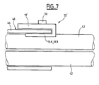
- Figs. 5 to 9 makes use of the same inventive principle (elongate member parallel to the axis of the receiving means for the branch cable) but differs considerably in its structure from the clamp element 10 of the first embodiment.
- the clamp element 10' seen in Figs. 5 and 6 comprises a curved base support 12' and an elongate member 16' designed to be inserted underneath the sheath 44 of the main cable 40, between two phase conductors.
- the curved base support 12' defines a cavity 14' for receiving the branch cable 46.
- the elongate member 16' comprises two elongate members 16A and 16B whose shape is frustoconical or pointed (conical or bevel-cut).
- a centering protuberance 30 Integral with the base support 12' is a centering protuberance 30.
- the protuberance 30 is designed to engage with a corresponding hole in a connector, for example the connector 32 seen in Fig. 9.
- a pair of elements 10' in accordance with the second embodiment can be placed on the main cable 40 on each side of the length of this cable where the outer sheath 44 has been removed; in such a case, the clamp elements 10' are maintained at a certain distance from each other using a special distance piece 34 (Fig. 8).
- a pair of elements 10' as seen in Fig. 8 can be preferred for convenience, and for reasons of stability.
- the elements 10' are then kept at the appropriate distance by the distance pieces 34 (which can also be removed before installing the connector 32).
- clamp element 10' in accordance with the second embodiment is used.
- a certain length of insulating sheath 44 is removed from the main cable 40 and the elongate members 16' of the various clamp elements are inserted underneath the sheath 44, in the space between two phase conductors 42.
- the distance between two opposite clamp elements 10' is preferably controlled/adjusted by means of the distance piece 34.
- a special connector 32 with means for creating the electrical contact between the phase conductors 42 of the main cable 40 and the corresponding branches 46 is fitted.
- the protuberance 30 is generally used only for one of the clamp elements 10' or one of the pairs of clamp elements 10', especially the one to be located near the neutral phase of the main cable 40. In such a case, it provides easy location of the neutral phase, as well as easy and non-faulty connection when only one hole in the connector 32, i.e. a hole located near the connection of the neutral phase, can cooperate with protuberance 30.
- the chief advantage of the clamp element according to the present invention is that it causes no damage at all to the insulation of the phase conductors of the main cable. This means greater safety for the electrician and more efficient, economical and safe junctions. The virtual impossibility of damaging the insulation of the phase conductors of the main cable also makes it unnecessary to renew this insulation with resins, mastic or silicone substances.
- FIG. 3 A similar embodiment as shown in Fig. 3 (i.e. use of projection 26 and protuberance 28) can also be applied to the embodiment of the clamp of the invention of Figs. 5 to 7.
- a protuberance 30 as shown in the embodiment of Figs. 5 to 7 can also be used in the clamp of Figs. 1 to 4.
Landscapes
- Installation Of Indoor Wiring (AREA)
- Cable Accessories (AREA)
- Clamps And Clips (AREA)
Abstract
Description
the clamp element being characterized in thatsaid elongate member is substantially parallel to the axis of said means for receiving said branch cable, so that it can be inserted underneath the sheath of said main cable, between one phase conductor and the adjacent phase conductor.
Claims (11)
- Clamp element (10, 10') for making a junction between at least one phase conductor (42) of a main cable (40) and at least one branch cable (46), said element (10, 10') comprising a base support (12, 12') with means (14, 14') for receiving said branch cable (46) and an elongate member (16, 16') projecting from said base support (12),
the clamp element (10, 10') being characterized in that said elongate member (16, 16') is substantially parallel to the axis of said means (14, 14') for receiving said branch cable (46), so that it can be inserted underneath the sheath of said main cable (40), between one phase conductor (42) and the adjacent phase conductor (42). - Clamp element (10, 10') according to claim 1, characterized in that said elongate member (16, 16') comprises at least one sharp extremity either conical or frustoconical.
- Clamp element (10, 10') according to anyone of claims 1 or 2, characterized in that it further comprises means (24, 26, 28) for securing it to the main cable (40).
- Clamp element (10, 10') according to claim 3, characterized in that said means (24, 26, 28) for securing it to the main cable comprise a strap (24).
- Clamp element (10, 10') according to anyone of claims 3 or 4, characterized in that said means (24, 26, 28) for securing it to the main cable comprise a projection (26).
- Clamp element (10, 10') according to claim 5, characterized in that said means (24, 26, 28) for securing it to the main cable comprise a protuberance (28) on said projection (26) to make a channel for the strap (24).
- Clamp element (10, 10') according to anyone of claims 5 or 6, characterized in that said projection (26) continues in the opposite direction to that of the elongate member (16).
- Clamp element (10) according to anyone of claims 4 to 7, characterized in that said means (24, 26, 28) for securing it to the main cable comprise a cavity in the base support (12) for insertion of the strap (24).
- Clamp element (10) according to anyone of claims 1 to 8, characterized in that said means for receiving said branch cable comprise a clip (14).
- Clamp element (10, 10') according to anyone of claims 1 to 9, characterized in that it also includes a centering protuberance (30) projecting from said base support (12).
- Clamp element (10, 10') according to anyone of claims 1 to 10, characterized in that it is made of a plastic material.
Applications Claiming Priority (2)
| Application Number | Priority Date | Filing Date | Title |
|---|---|---|---|
| ITMI002327 | 2000-10-27 | ||
| IT2000MI002327 IT1319030B1 (en) | 2000-10-27 | 2000-10-27 | CLAMPING ELEMENT FOR ELECTRIC CABLES JUNCTION |
Publications (3)
| Publication Number | Publication Date |
|---|---|
| EP1213793A2 true EP1213793A2 (en) | 2002-06-12 |
| EP1213793A3 EP1213793A3 (en) | 2004-06-02 |
| EP1213793B1 EP1213793B1 (en) | 2005-12-28 |
Family
ID=11446048
Family Applications (1)
| Application Number | Title | Priority Date | Filing Date |
|---|---|---|---|
| EP20010402801 Expired - Lifetime EP1213793B1 (en) | 2000-10-27 | 2001-10-29 | Clamp for electrical cables |
Country Status (3)
| Country | Link |
|---|---|
| EP (1) | EP1213793B1 (en) |
| DE (1) | DE60116245T2 (en) |
| IT (1) | IT1319030B1 (en) |
Family Cites Families (3)
| Publication number | Priority date | Publication date | Assignee | Title |
|---|---|---|---|---|
| DE1765880B2 (en) * | 1968-07-31 | 1973-03-22 | Fa. Richard Bergner, 8540 Schwabach | CABLE JUNCTION TERMINAL |
| GB1369794A (en) * | 1971-09-08 | 1974-10-09 | Pirelli General Cable Works | Electrical connectors |
| DE2628633C2 (en) * | 1976-06-25 | 1982-07-29 | Felten & Guilleaume Energietechnik GmbH, 5000 Köln | Multi-phase branch terminal for plastic cables in the low voltage range |
-
2000
- 2000-10-27 IT IT2000MI002327 patent/IT1319030B1/en active
-
2001
- 2001-10-29 DE DE2001616245 patent/DE60116245T2/en not_active Expired - Lifetime
- 2001-10-29 EP EP20010402801 patent/EP1213793B1/en not_active Expired - Lifetime
Also Published As
| Publication number | Publication date |
|---|---|
| DE60116245D1 (en) | 2006-02-02 |
| EP1213793B1 (en) | 2005-12-28 |
| EP1213793A3 (en) | 2004-06-02 |
| IT1319030B1 (en) | 2003-09-19 |
| DE60116245T2 (en) | 2006-08-24 |
| ITMI20002327A1 (en) | 2002-04-27 |
Similar Documents
| Publication | Publication Date | Title |
|---|---|---|
| RU2164357C2 (en) | Device for distributing optical fiber joints | |
| RU2165095C2 (en) | Enclosure in the form of cap for fiber-optical cables | |
| KR100299367B1 (en) | Fiber Optic Splicer | |
| CN101981760A (en) | Communication cable entry equipment | |
| US5048916A (en) | Fiber optic connection system | |
| USRE43221E1 (en) | Structured cabling system and method | |
| JPH024202A (en) | Cable envelope and assembling thereof | |
| US5117067A (en) | Environmentally sealed pedestal | |
| JP2011525695A (en) | Telecommunications cable entry device | |
| CA2085271A1 (en) | Optical fiber closure | |
| CN102474039A (en) | Sealing member | |
| BR112016016405B1 (en) | PLUG CONNECTOR AND PLUG CONNECTOR DEVICE | |
| WO2009037450A2 (en) | A cable duct restraining device | |
| EP1213793B1 (en) | Clamp for electrical cables | |
| CN1217094A (en) | Apparatus and method for cable branching | |
| FI68484C (en) | ANORDING WITH ELDOSA | |
| US6736715B2 (en) | Electrical junction assembly and related splicing method | |
| CN218216559U (en) | Cable fixing clamp | |
| US7090530B1 (en) | Quick connect electrical box | |
| US6262373B1 (en) | Cable strain relief bracket | |
| US20220149609A1 (en) | Cable retention device, system and method | |
| EP1202420B1 (en) | Insulating container for a branch junction for electrical cables | |
| DK154381B (en) | CONNECTION AND BRANCHING DASE TO TELECABLES | |
| CN218335295U (en) | Cable connection department insulation protection device | |
| KR200273405Y1 (en) | Insulting Protection Cover of Clamp for Wire Fixed |
Legal Events
| Date | Code | Title | Description |
|---|---|---|---|
| PUAI | Public reference made under article 153(3) epc to a published international application that has entered the european phase |
Free format text: ORIGINAL CODE: 0009012 |
|
| AK | Designated contracting states |
Kind code of ref document: A2 Designated state(s): AT BE CH CY DE DK ES FI FR GB GR IE IT LI LU MC NL PT SE TR |
|
| AX | Request for extension of the european patent |
Free format text: AL;LT;LV;MK;RO;SI |
|
| PUAL | Search report despatched |
Free format text: ORIGINAL CODE: 0009013 |
|
| AK | Designated contracting states |
Kind code of ref document: A3 Designated state(s): AT BE CH CY DE DK ES FI FR GB GR IE IT LI LU MC NL PT SE TR |
|
| AX | Request for extension of the european patent |
Extension state: AL LT LV MK RO SI |
|
| 17P | Request for examination filed |
Effective date: 20041202 |
|
| AKX | Designation fees paid |
Designated state(s): AT BE CH CY DE DK ES FI FR GB GR IE IT LI LU MC NL PT SE TR |
|
| GRAP | Despatch of communication of intention to grant a patent |
Free format text: ORIGINAL CODE: EPIDOSNIGR1 |
|
| GRAS | Grant fee paid |
Free format text: ORIGINAL CODE: EPIDOSNIGR3 |
|
| GRAA | (expected) grant |
Free format text: ORIGINAL CODE: 0009210 |
|
| AK | Designated contracting states |
Kind code of ref document: B1 Designated state(s): AT BE CH CY DE DK ES FI FR GB GR IE IT LI LU MC NL PT SE TR |
|
| PG25 | Lapsed in a contracting state [announced via postgrant information from national office to epo] |
Ref country code: IT Free format text: LAPSE BECAUSE OF FAILURE TO SUBMIT A TRANSLATION OF THE DESCRIPTION OR TO PAY THE FEE WITHIN THE PRESCRIBED TIME-LIMIT;WARNING: LAPSES OF ITALIAN PATENTS WITH EFFECTIVE DATE BEFORE 2007 MAY HAVE OCCURRED AT ANY TIME BEFORE 2007. THE CORRECT EFFECTIVE DATE MAY BE DIFFERENT FROM THE ONE RECORDED. Effective date: 20051228 Ref country code: FI Free format text: LAPSE BECAUSE OF FAILURE TO SUBMIT A TRANSLATION OF THE DESCRIPTION OR TO PAY THE FEE WITHIN THE PRESCRIBED TIME-LIMIT Effective date: 20051228 Ref country code: AT Free format text: LAPSE BECAUSE OF FAILURE TO SUBMIT A TRANSLATION OF THE DESCRIPTION OR TO PAY THE FEE WITHIN THE PRESCRIBED TIME-LIMIT Effective date: 20051228 Ref country code: NL Free format text: LAPSE BECAUSE OF FAILURE TO SUBMIT A TRANSLATION OF THE DESCRIPTION OR TO PAY THE FEE WITHIN THE PRESCRIBED TIME-LIMIT Effective date: 20051228 |
|
| REG | Reference to a national code |
Ref country code: GB Ref legal event code: FG4D |
|
| REG | Reference to a national code |
Ref country code: CH Ref legal event code: EP |
|
| REG | Reference to a national code |
Ref country code: IE Ref legal event code: FG4D |
|
| REF | Corresponds to: |
Ref document number: 60116245 Country of ref document: DE Date of ref document: 20060202 Kind code of ref document: P |
|
| PG25 | Lapsed in a contracting state [announced via postgrant information from national office to epo] |
Ref country code: GR Free format text: LAPSE BECAUSE OF FAILURE TO SUBMIT A TRANSLATION OF THE DESCRIPTION OR TO PAY THE FEE WITHIN THE PRESCRIBED TIME-LIMIT Effective date: 20060328 Ref country code: DK Free format text: LAPSE BECAUSE OF FAILURE TO SUBMIT A TRANSLATION OF THE DESCRIPTION OR TO PAY THE FEE WITHIN THE PRESCRIBED TIME-LIMIT Effective date: 20060328 |
|
| PG25 | Lapsed in a contracting state [announced via postgrant information from national office to epo] |
Ref country code: ES Free format text: LAPSE BECAUSE OF FAILURE TO SUBMIT A TRANSLATION OF THE DESCRIPTION OR TO PAY THE FEE WITHIN THE PRESCRIBED TIME-LIMIT Effective date: 20060408 |
|
| REG | Reference to a national code |
Ref country code: SE Ref legal event code: TRGR |
|
| PG25 | Lapsed in a contracting state [announced via postgrant information from national office to epo] |
Ref country code: PT Free format text: LAPSE BECAUSE OF FAILURE TO SUBMIT A TRANSLATION OF THE DESCRIPTION OR TO PAY THE FEE WITHIN THE PRESCRIBED TIME-LIMIT Effective date: 20060529 |
|
| NLV1 | Nl: lapsed or annulled due to failure to fulfill the requirements of art. 29p and 29m of the patents act | ||
| ET | Fr: translation filed | ||
| PG25 | Lapsed in a contracting state [announced via postgrant information from national office to epo] |
Ref country code: IE Free format text: LAPSE BECAUSE OF NON-PAYMENT OF DUE FEES Effective date: 20061030 |
|
| PG25 | Lapsed in a contracting state [announced via postgrant information from national office to epo] |
Ref country code: MC Free format text: LAPSE BECAUSE OF NON-PAYMENT OF DUE FEES Effective date: 20061031 |
|
| PLBE | No opposition filed within time limit |
Free format text: ORIGINAL CODE: 0009261 |
|
| STAA | Information on the status of an ep patent application or granted ep patent |
Free format text: STATUS: NO OPPOSITION FILED WITHIN TIME LIMIT |
|
| 26N | No opposition filed |
Effective date: 20060929 |
|
| REG | Reference to a national code |
Ref country code: IE Ref legal event code: MM4A |
|
| PG25 | Lapsed in a contracting state [announced via postgrant information from national office to epo] |
Ref country code: LU Free format text: LAPSE BECAUSE OF NON-PAYMENT OF DUE FEES Effective date: 20061029 Ref country code: TR Free format text: LAPSE BECAUSE OF FAILURE TO SUBMIT A TRANSLATION OF THE DESCRIPTION OR TO PAY THE FEE WITHIN THE PRESCRIBED TIME-LIMIT Effective date: 20051228 |
|
| PG25 | Lapsed in a contracting state [announced via postgrant information from national office to epo] |
Ref country code: CY Free format text: LAPSE BECAUSE OF FAILURE TO SUBMIT A TRANSLATION OF THE DESCRIPTION OR TO PAY THE FEE WITHIN THE PRESCRIBED TIME-LIMIT Effective date: 20051228 |
|
| PGFP | Annual fee paid to national office [announced via postgrant information from national office to epo] |
Ref country code: CH Payment date: 20091026 Year of fee payment: 9 |
|
| PGFP | Annual fee paid to national office [announced via postgrant information from national office to epo] |
Ref country code: GB Payment date: 20091022 Year of fee payment: 9 |
|
| PGFP | Annual fee paid to national office [announced via postgrant information from national office to epo] |
Ref country code: BE Payment date: 20101013 Year of fee payment: 10 Ref country code: SE Payment date: 20101014 Year of fee payment: 10 |
|
| REG | Reference to a national code |
Ref country code: CH Ref legal event code: PL |
|
| GBPC | Gb: european patent ceased through non-payment of renewal fee |
Effective date: 20101029 |
|
| PG25 | Lapsed in a contracting state [announced via postgrant information from national office to epo] |
Ref country code: CH Free format text: LAPSE BECAUSE OF NON-PAYMENT OF DUE FEES Effective date: 20101031 Ref country code: LI Free format text: LAPSE BECAUSE OF NON-PAYMENT OF DUE FEES Effective date: 20101031 |
|
| PG25 | Lapsed in a contracting state [announced via postgrant information from national office to epo] |
Ref country code: GB Free format text: LAPSE BECAUSE OF NON-PAYMENT OF DUE FEES Effective date: 20101029 |
|
| BERE | Be: lapsed |
Owner name: *NEXANS Effective date: 20111031 |
|
| REG | Reference to a national code |
Ref country code: SE Ref legal event code: EUG |
|
| PG25 | Lapsed in a contracting state [announced via postgrant information from national office to epo] |
Ref country code: BE Free format text: LAPSE BECAUSE OF NON-PAYMENT OF DUE FEES Effective date: 20111031 |
|
| PG25 | Lapsed in a contracting state [announced via postgrant information from national office to epo] |
Ref country code: SE Free format text: LAPSE BECAUSE OF NON-PAYMENT OF DUE FEES Effective date: 20111030 |
|
| PGFP | Annual fee paid to national office [announced via postgrant information from national office to epo] |
Ref country code: DE Payment date: 20121023 Year of fee payment: 12 Ref country code: FR Payment date: 20121031 Year of fee payment: 12 |
|
| PGFP | Annual fee paid to national office [announced via postgrant information from national office to epo] |
Ref country code: IT Payment date: 20121025 Year of fee payment: 12 |
|
| REG | Reference to a national code |
Ref country code: FR Ref legal event code: ST Effective date: 20140630 |
|
| REG | Reference to a national code |
Ref country code: DE Ref legal event code: R119 Ref document number: 60116245 Country of ref document: DE Effective date: 20140501 |
|
| PG25 | Lapsed in a contracting state [announced via postgrant information from national office to epo] |
Ref country code: DE Free format text: LAPSE BECAUSE OF NON-PAYMENT OF DUE FEES Effective date: 20140501 Ref country code: IT Free format text: LAPSE BECAUSE OF NON-PAYMENT OF DUE FEES Effective date: 20131029 Ref country code: FR Free format text: LAPSE BECAUSE OF NON-PAYMENT OF DUE FEES Effective date: 20131031 |