EP1213748A2 - Semiconductor substrate and method for fabricating the same - Google Patents
Semiconductor substrate and method for fabricating the same Download PDFInfo
- Publication number
- EP1213748A2 EP1213748A2 EP01128164A EP01128164A EP1213748A2 EP 1213748 A2 EP1213748 A2 EP 1213748A2 EP 01128164 A EP01128164 A EP 01128164A EP 01128164 A EP01128164 A EP 01128164A EP 1213748 A2 EP1213748 A2 EP 1213748A2
- Authority
- EP
- European Patent Office
- Prior art keywords
- semiconductor substrate
- insulating film
- resist layer
- concave
- semiconductor
- Prior art date
- Legal status (The legal status is an assumption and is not a legal conclusion. Google has not performed a legal analysis and makes no representation as to the accuracy of the status listed.)
- Withdrawn
Links
Images


Classifications
-
- H—ELECTRICITY
- H10—SEMICONDUCTOR DEVICES; ELECTRIC SOLID-STATE DEVICES NOT OTHERWISE PROVIDED FOR
- H10D—INORGANIC ELECTRIC SEMICONDUCTOR DEVICES
- H10D84/00—Integrated devices formed in or on semiconductor substrates that comprise only semiconducting layers, e.g. on Si wafers or on GaAs-on-Si wafers
- H10D84/01—Manufacture or treatment
-
- H—ELECTRICITY
- H10—SEMICONDUCTOR DEVICES; ELECTRIC SOLID-STATE DEVICES NOT OTHERWISE PROVIDED FOR
- H10P—GENERIC PROCESSES OR APPARATUS FOR THE MANUFACTURE OR TREATMENT OF DEVICES COVERED BY CLASS H10
- H10P90/00—Preparation of wafers not covered by a single main group of this subclass, e.g. wafer reinforcement
- H10P90/19—Preparing inhomogeneous wafers
- H10P90/1904—Preparing vertically inhomogeneous wafers
- H10P90/1906—Preparing SOI wafers
- H10P90/1914—Preparing SOI wafers using bonding
- H10P90/1916—Preparing SOI wafers using bonding with separation or delamination along an ion implanted layer, e.g. Smart-cut
-
- H—ELECTRICITY
- H10—SEMICONDUCTOR DEVICES; ELECTRIC SOLID-STATE DEVICES NOT OTHERWISE PROVIDED FOR
- H10W—GENERIC PACKAGES, INTERCONNECTIONS, CONNECTORS OR OTHER CONSTRUCTIONAL DETAILS OF DEVICES COVERED BY CLASS H10
- H10W10/00—Isolation regions in semiconductor bodies between components of integrated devices
- H10W10/01—Manufacture or treatment
- H10W10/021—Manufacture or treatment of air gaps
-
- H—ELECTRICITY
- H10—SEMICONDUCTOR DEVICES; ELECTRIC SOLID-STATE DEVICES NOT OTHERWISE PROVIDED FOR
- H10W—GENERIC PACKAGES, INTERCONNECTIONS, CONNECTORS OR OTHER CONSTRUCTIONAL DETAILS OF DEVICES COVERED BY CLASS H10
- H10W10/00—Isolation regions in semiconductor bodies between components of integrated devices
- H10W10/10—Isolation regions comprising dielectric materials
- H10W10/181—Semiconductor-on-insulator [SOI] isolation regions, e.g. buried oxide regions of SOI wafers
-
- H—ELECTRICITY
- H10—SEMICONDUCTOR DEVICES; ELECTRIC SOLID-STATE DEVICES NOT OTHERWISE PROVIDED FOR
- H10W—GENERIC PACKAGES, INTERCONNECTIONS, CONNECTORS OR OTHER CONSTRUCTIONAL DETAILS OF DEVICES COVERED BY CLASS H10
- H10W10/00—Isolation regions in semiconductor bodies between components of integrated devices
- H10W10/20—Air gaps
Definitions
- the cavity 3 is formed in the bottom portion of the semiconductor substrate 1 in a position opposing the bonding pad 2 . By providing the cavity 3 at this position, the parasitic capacitance generated between the semiconductor substrate 1 and the bonding pad 2 can be reduced.
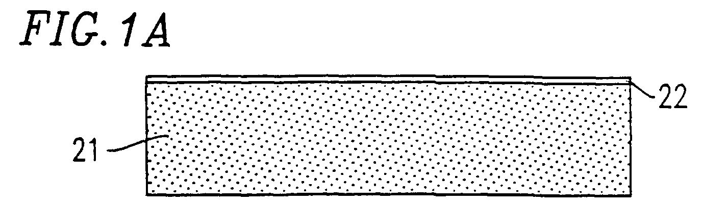
- a cavity 21c is formed in the first semiconductor substrate 21 before forming circuit elements (not shown). Therefore, it is not required to form the cavity 21c in the semiconductor substrate device after forming the circuit elements. Accordingly, damages to the circuit elements which may occur when forming cavities after the circuit elements are formed can be avoided, unlike in the methods of documents 1 and 2.
Landscapes
- Internal Circuitry In Semiconductor Integrated Circuit Devices (AREA)
- Element Separation (AREA)
- Thin Film Transistor (AREA)
- Semiconductor Integrated Circuits (AREA)
Abstract


Description
Claims (5)
- A semiconductor substrate device, comprising:wherein the first semiconductor substrate and the second semiconductor substrate are brought together so that the surface of the first semiconductor substrate and the insulating film provided on the surface of the second semiconductor substrate contact each other to form a cavity in the semiconductor substrate device.a first semiconductor substrate including a concave-convex surface; anda second semiconductor substrate having an insulating film on a surface thereof,
- A semiconductor substrate device according to claim 1, wherein the concave-convex surface of the first semiconductor substrate is defined by a plurality of convex portions formed at equal intervals.
- A method for fabricating a semiconductor substrate device, comprising the steps of:providing a resist layer having a predetermined pattern on a first insulating film on a first semiconductor substrate;performing isotropic or anisotropic etching of the first insulating film by using the resist layer as a mask, and performing anisotropic etching of the first semiconductor substrate by using the resist layer as a mask to form a concave-convex portion in a surface of the first semiconductor substrate to provide the first semiconductor substrate with the concave-convex surface; andremoving the resist layer and the first insulating film, and then bringing the first semiconductor substrate and a second semiconductor substrate together so that the surface of the first semiconductor substrate and a second insulating film provided on a surface of the second semiconductor substrate contact each other.
- A method according to claim 3, further comprising the step of thinning the second semiconductor substrate from a surface opposite to the surface thereof provided with the second insulating film after the step of bringing the first semiconductor substrate and the second semiconductor substrate together.
- A method according to claim 3, wherein the anisotropic etching of the first semiconductor substrate is performed by using KOH.
Applications Claiming Priority (2)
| Application Number | Priority Date | Filing Date | Title |
|---|---|---|---|
| JP2000361979 | 2000-11-28 | ||
| JP2000361979A JP3957038B2 (en) | 2000-11-28 | 2000-11-28 | Semiconductor substrate and manufacturing method thereof |
Publications (2)
| Publication Number | Publication Date |
|---|---|
| EP1213748A2 true EP1213748A2 (en) | 2002-06-12 |
| EP1213748A3 EP1213748A3 (en) | 2004-05-12 |
Family
ID=18833329
Family Applications (1)
| Application Number | Title | Priority Date | Filing Date |
|---|---|---|---|
| EP01128164A Withdrawn EP1213748A3 (en) | 2000-11-28 | 2001-11-27 | Semiconductor substrate and method for fabricating the same |
Country Status (5)
| Country | Link |
|---|---|
| US (1) | US6812508B2 (en) |
| EP (1) | EP1213748A3 (en) |
| JP (1) | JP3957038B2 (en) |
| KR (1) | KR100423780B1 (en) |
| TW (1) | TW531856B (en) |
Cited By (7)
| Publication number | Priority date | Publication date | Assignee | Title |
|---|---|---|---|---|
| WO2004038790A1 (en) | 2002-10-22 | 2004-05-06 | Sumitomo Mitsubishi Silicon Corporation | Pasted soi substrate, process for producing the same and semiconductor device |
| WO2004057663A1 (en) * | 2002-12-19 | 2004-07-08 | Koninklijke Philips Electronics N.V. | Stress-free composite substrate and method of manufacturing such a composite substrate |
| EP1571705A3 (en) * | 2004-03-01 | 2006-01-04 | S.O.I.Tec Silicon on Insulator Technologies | Process of making a semiconductor structure on a substrate |
| US7176554B2 (en) | 2004-03-01 | 2007-02-13 | S.O.I. Tec Silicon On Insulator Technologies S.A. | Methods for producing a semiconductor entity |
| WO2008076651A1 (en) * | 2006-12-15 | 2008-06-26 | Hvvi Semiconductors, Inc. | Semiconductor structure and method of manufacture |
| EP1986226A1 (en) * | 2007-04-25 | 2008-10-29 | Semiconductor Energy Laboratory Co., Ltd. | Semiconductor device and method for manufacturing the same |
| FR2973569A1 (en) * | 2011-04-01 | 2012-10-05 | St Microelectronics Sa | Integrated circuit manufacturing method, involves removing part of plate to leave silicon residual layer on insulating layer, and forming high frequency component in and/or above residual layer, or directly above some of cavities |
Families Citing this family (38)
| Publication number | Priority date | Publication date | Assignee | Title |
|---|---|---|---|---|
| US5949144A (en) * | 1996-05-20 | 1999-09-07 | Harris Corporation | Pre-bond cavity air bridge |
| US6862934B2 (en) * | 2001-10-05 | 2005-03-08 | The Charles Stark Draper Laboratory, Inc. | Tuning fork gyroscope |
| JP3813079B2 (en) * | 2001-10-11 | 2006-08-23 | 沖電気工業株式会社 | Chip size package |
| US7198974B2 (en) * | 2003-03-05 | 2007-04-03 | Micron Technology, Inc. | Micro-mechanically strained semiconductor film |
| US7220656B2 (en) | 2003-04-29 | 2007-05-22 | Micron Technology, Inc. | Strained semiconductor by wafer bonding with misorientation |
| US7041575B2 (en) * | 2003-04-29 | 2006-05-09 | Micron Technology, Inc. | Localized strained semiconductor on insulator |
| US7115480B2 (en) | 2003-05-07 | 2006-10-03 | Micron Technology, Inc. | Micromechanical strained semiconductor by wafer bonding |
| US7008854B2 (en) | 2003-05-21 | 2006-03-07 | Micron Technology, Inc. | Silicon oxycarbide substrates for bonded silicon on insulator |
| US7273788B2 (en) * | 2003-05-21 | 2007-09-25 | Micron Technology, Inc. | Ultra-thin semiconductors bonded on glass substrates |
| KR100510821B1 (en) * | 2003-06-09 | 2005-08-30 | 한국전자통신연구원 | Fabrication method using a temporary substrate of micro structures |
| US7153753B2 (en) | 2003-08-05 | 2006-12-26 | Micron Technology, Inc. | Strained Si/SiGe/SOI islands and processes of making same |
| KR100664986B1 (en) | 2004-10-29 | 2007-01-09 | 삼성전기주식회사 | Nitride-based semiconductor device using nanorods and manufacturing method thereof |
| CN100468029C (en) * | 2005-03-03 | 2009-03-11 | 清华大学 | Standard leaks and methods of making them |
| US7190050B2 (en) * | 2005-07-01 | 2007-03-13 | Synopsys, Inc. | Integrated circuit on corrugated substrate |
| US7265008B2 (en) | 2005-07-01 | 2007-09-04 | Synopsys, Inc. | Method of IC production using corrugated substrate |
| US7247887B2 (en) * | 2005-07-01 | 2007-07-24 | Synopsys, Inc. | Segmented channel MOS transistor |
| US8946674B2 (en) | 2005-08-31 | 2015-02-03 | University Of Florida Research Foundation, Inc. | Group III-nitrides on Si substrates using a nanostructured interlayer |
| US7439159B2 (en) * | 2005-10-28 | 2008-10-21 | Kulite Semiconductor Products, Inc. | Fusion bonding process and structure for fabricating silicon-on-insulator (SOI) semiconductor devices |
| US7544584B2 (en) | 2006-02-16 | 2009-06-09 | Micron Technology, Inc. | Localized compressive strained semiconductor |
| JP2007326771A (en) * | 2006-05-30 | 2007-12-20 | Sharp Corp | Formation method and compound semiconductor wafer |
| US8222057B2 (en) | 2006-08-29 | 2012-07-17 | University Of Florida Research Foundation, Inc. | Crack free multilayered devices, methods of manufacture thereof and articles comprising the same |
| US8674472B2 (en) * | 2010-08-10 | 2014-03-18 | International Business Machines Corporation | Low harmonic RF switch in SOI |
| US8536021B2 (en) | 2010-12-24 | 2013-09-17 | Io Semiconductor, Inc. | Trap rich layer formation techniques for semiconductor devices |
| US8481405B2 (en) | 2010-12-24 | 2013-07-09 | Io Semiconductor, Inc. | Trap rich layer with through-silicon-vias in semiconductor devices |
| US9754860B2 (en) | 2010-12-24 | 2017-09-05 | Qualcomm Incorporated | Redistribution layer contacting first wafer through second wafer |
| US9624096B2 (en) | 2010-12-24 | 2017-04-18 | Qualcomm Incorporated | Forming semiconductor structure with device layers and TRL |
| EP3734645B1 (en) | 2010-12-24 | 2025-09-10 | Qualcomm Incorporated | Trap rich layer for semiconductor devices |
| US9553013B2 (en) | 2010-12-24 | 2017-01-24 | Qualcomm Incorporated | Semiconductor structure with TRL and handle wafer cavities |
| JP2012204543A (en) | 2011-03-24 | 2012-10-22 | Toshiba Corp | Semiconductor device and manufacturing method thereof |
| US9184094B1 (en) * | 2012-01-26 | 2015-11-10 | Skorpios Technologies, Inc. | Method and system for forming a membrane over a cavity |
| JP5933289B2 (en) * | 2012-02-23 | 2016-06-08 | 三菱電機株式会社 | SOI wafer and manufacturing method thereof |
| US9190346B2 (en) | 2012-08-31 | 2015-11-17 | Synopsys, Inc. | Latch-up suppression and substrate noise coupling reduction through a substrate back-tie for 3D integrated circuits |
| US9817928B2 (en) | 2012-08-31 | 2017-11-14 | Synopsys, Inc. | Latch-up suppression and substrate noise coupling reduction through a substrate back-tie for 3D integrated circuits |
| US8847324B2 (en) | 2012-12-17 | 2014-09-30 | Synopsys, Inc. | Increasing ION /IOFF ratio in FinFETs and nano-wires |
| US9379018B2 (en) | 2012-12-17 | 2016-06-28 | Synopsys, Inc. | Increasing Ion/Ioff ratio in FinFETs and nano-wires |
| US10411135B2 (en) | 2015-06-08 | 2019-09-10 | Synopsys, Inc. | Substrates and transistors with 2D material channels on 3D geometries |
| CN220502678U (en) | 2019-01-16 | 2024-02-20 | 株式会社村田制作所 | Silicon substrate with cavity and cavity SOI substrate using the silicon substrate |
| CN111952241A (en) * | 2020-08-21 | 2020-11-17 | 中国科学院上海微系统与信息技术研究所 | Semiconductor substrate with auxiliary support structure and preparation method thereof |
Family Cites Families (33)
| Publication number | Priority date | Publication date | Assignee | Title |
|---|---|---|---|---|
| US3924322A (en) * | 1973-12-11 | 1975-12-09 | Kulite Semiconductor Products | Economical pressure transducer assemblies, methods of fabricating and mounting the same |
| US4169000A (en) * | 1976-09-02 | 1979-09-25 | International Business Machines Corporation | Method of forming an integrated circuit structure with fully-enclosed air isolation |
| JPS6051700A (en) * | 1983-08-31 | 1985-03-23 | Toshiba Corp | Bonding method of silicon crystalline body |
| JPS61184843A (en) * | 1985-02-13 | 1986-08-18 | Toshiba Corp | Composite semiconductor device and manufacture thereof |
| US4975390A (en) * | 1986-12-18 | 1990-12-04 | Nippondenso Co. Ltd. | Method of fabricating a semiconductor pressure sensor |
| US5004705A (en) * | 1989-01-06 | 1991-04-02 | Unitrode Corporation | Inverted epitaxial process |
| JP2825322B2 (en) | 1989-09-13 | 1998-11-18 | 株式会社東芝 | Method for manufacturing semiconductor substrate having dielectric isolation structure |
| GB2237929A (en) * | 1989-10-23 | 1991-05-15 | Philips Electronic Associated | A method of manufacturing a semiconductor device |
| JPH03196644A (en) | 1989-12-26 | 1991-08-28 | Nec Corp | Semiconductor integrated circuit |
| JP2729005B2 (en) * | 1992-04-01 | 1998-03-18 | 三菱電機株式会社 | Semiconductor pressure sensor and method of manufacturing the same |
| US5264375A (en) * | 1992-04-15 | 1993-11-23 | Massachusetts Institute Of Technology | Superconducting detector and method of making same |
| KR940008557A (en) | 1992-10-30 | 1994-05-16 | 이동우 | Mushroom cultivation medium and preparation method thereof |
| US5286671A (en) * | 1993-05-07 | 1994-02-15 | Kulite Semiconductor Products, Inc. | Fusion bonding technique for use in fabricating semiconductor devices |
| US5476819A (en) * | 1993-07-26 | 1995-12-19 | Litton Systems, Inc. | Substrate anchor for undercut silicon on insulator microstructures |
| JP3247533B2 (en) * | 1994-02-04 | 2002-01-15 | 本田技研工業株式会社 | Manufacturing method of semiconductor gas rate sensor |
| US5516720A (en) * | 1994-02-14 | 1996-05-14 | United Microelectronics Corporation | Stress relaxation in dielectric before metallization |
| US5648665A (en) * | 1994-04-28 | 1997-07-15 | Ngk Insulators, Ltd. | Semiconductor device having a plurality of cavity defined gating regions and a fabrication method therefor |
| US5473944A (en) * | 1994-08-18 | 1995-12-12 | Kulite Semi Conductor Products, Inc. | Seam pressure sensor employing dielectically isolated resonant beams and related method of manufacture |
| JP3214987B2 (en) * | 1994-09-05 | 2001-10-02 | 日本碍子株式会社 | Semiconductor device and method of manufacturing the same |
| US5620614A (en) * | 1995-01-03 | 1997-04-15 | Xerox Corporation | Printhead array and method of producing a printhead die assembly that minimizes end channel damage |
| JP3613838B2 (en) * | 1995-05-18 | 2005-01-26 | 株式会社デンソー | Manufacturing method of semiconductor device |
| US5681775A (en) * | 1995-11-15 | 1997-10-28 | International Business Machines Corporation | Soi fabrication process |
| FR2748851B1 (en) * | 1996-05-15 | 1998-08-07 | Commissariat Energie Atomique | PROCESS FOR PRODUCING A THIN FILM OF SEMICONDUCTOR MATERIAL |
| US5949144A (en) | 1996-05-20 | 1999-09-07 | Harris Corporation | Pre-bond cavity air bridge |
| JPH09318474A (en) * | 1996-05-29 | 1997-12-12 | Tokai Rika Co Ltd | Manufacturing method of sensor |
| US5863832A (en) * | 1996-06-28 | 1999-01-26 | Intel Corporation | Capping layer in interconnect system and method for bonding the capping layer onto the interconnect system |
| US6448624B1 (en) * | 1996-08-09 | 2002-09-10 | Denso Corporation | Semiconductor acceleration sensor |
| US5726453A (en) * | 1996-09-30 | 1998-03-10 | Westinghouse Electric Corporation | Radiation resistant solid state neutron detector |
| US6306729B1 (en) | 1997-12-26 | 2001-10-23 | Canon Kabushiki Kaisha | Semiconductor article and method of manufacturing the same |
| JP3013932B2 (en) | 1997-12-26 | 2000-02-28 | キヤノン株式会社 | Semiconductor member manufacturing method and semiconductor member |
| US6143583A (en) * | 1998-06-08 | 2000-11-07 | Honeywell, Inc. | Dissolved wafer fabrication process and associated microelectromechanical device having a support substrate with spacing mesas |
| TW401618B (en) * | 1998-09-23 | 2000-08-11 | Nat Science Council | Manufacture method of the dielectrics and the structure thereof |
| US6503847B2 (en) * | 2001-04-26 | 2003-01-07 | Institute Of Microelectronics | Room temperature wafer-to-wafer bonding by polydimethylsiloxane |
-
2000
- 2000-11-28 JP JP2000361979A patent/JP3957038B2/en not_active Expired - Fee Related
-
2001
- 2001-11-27 US US09/993,897 patent/US6812508B2/en not_active Expired - Fee Related
- 2001-11-27 EP EP01128164A patent/EP1213748A3/en not_active Withdrawn
- 2001-11-27 KR KR10-2001-0074205A patent/KR100423780B1/en not_active Expired - Fee Related
- 2001-11-27 TW TW090129331A patent/TW531856B/en not_active IP Right Cessation
Cited By (13)
| Publication number | Priority date | Publication date | Assignee | Title |
|---|---|---|---|---|
| US7253082B2 (en) | 2002-10-22 | 2007-08-07 | Sumitomo Mitsubishi Silicon Corporation | Pasted SOI substrate, process for producing the same and semiconductor device |
| CN100474554C (en) * | 2002-10-22 | 2009-04-01 | 三菱住友硅晶株式会社 | Bonded SOI substrate, method for manufacturing the same, and semiconductor device |
| WO2004038790A1 (en) | 2002-10-22 | 2004-05-06 | Sumitomo Mitsubishi Silicon Corporation | Pasted soi substrate, process for producing the same and semiconductor device |
| KR100734229B1 (en) * | 2002-10-22 | 2007-07-02 | 주식회사 사무코 | Pasted soi substrate, process for producing the same and semiconductor device |
| WO2004057663A1 (en) * | 2002-12-19 | 2004-07-08 | Koninklijke Philips Electronics N.V. | Stress-free composite substrate and method of manufacturing such a composite substrate |
| US7176554B2 (en) | 2004-03-01 | 2007-02-13 | S.O.I. Tec Silicon On Insulator Technologies S.A. | Methods for producing a semiconductor entity |
| US7439160B2 (en) | 2004-03-01 | 2008-10-21 | S.O.I.Tec Silicon On Insulator Technologies | Methods for producing a semiconductor entity |
| EP1571705A3 (en) * | 2004-03-01 | 2006-01-04 | S.O.I.Tec Silicon on Insulator Technologies | Process of making a semiconductor structure on a substrate |
| WO2008076651A1 (en) * | 2006-12-15 | 2008-06-26 | Hvvi Semiconductors, Inc. | Semiconductor structure and method of manufacture |
| US7888746B2 (en) | 2006-12-15 | 2011-02-15 | Hvvi Semiconductors, Inc. | Semiconductor structure and method of manufacture |
| EP1986226A1 (en) * | 2007-04-25 | 2008-10-29 | Semiconductor Energy Laboratory Co., Ltd. | Semiconductor device and method for manufacturing the same |
| US8212319B2 (en) | 2007-04-25 | 2012-07-03 | Semiconductor Energy Laboratory Co., Ltd. | Semiconductor device comprising semiconductor film with recess |
| FR2973569A1 (en) * | 2011-04-01 | 2012-10-05 | St Microelectronics Sa | Integrated circuit manufacturing method, involves removing part of plate to leave silicon residual layer on insulating layer, and forming high frequency component in and/or above residual layer, or directly above some of cavities |
Also Published As
| Publication number | Publication date |
|---|---|
| KR20020041765A (en) | 2002-06-03 |
| JP2002164521A (en) | 2002-06-07 |
| JP3957038B2 (en) | 2007-08-08 |
| TW531856B (en) | 2003-05-11 |
| US20020063341A1 (en) | 2002-05-30 |
| US6812508B2 (en) | 2004-11-02 |
| KR100423780B1 (en) | 2004-03-22 |
| EP1213748A3 (en) | 2004-05-12 |
Similar Documents
| Publication | Publication Date | Title |
|---|---|---|
| US6812508B2 (en) | Semiconductor substrate and method for fabricating the same | |
| US7393730B2 (en) | Coplanar silicon-on-insulator (SOI) regions of different crystal orientations and methods of making the same | |
| US6949420B1 (en) | Silicon-on-insulator (SOI) substrate having dual surface crystallographic orientations and method of forming same | |
| JP2003179148A (en) | Semiconductor substrate and method of manufacturing the same | |
| JPH03129854A (en) | Manufacture of semiconductor device | |
| US6933590B2 (en) | Semiconductor device comprising plurality of semiconductor areas having the same top surface and different film thicknesses and manufacturing method for the same | |
| JP4029884B2 (en) | Manufacturing method of semiconductor device | |
| JP2004214596A (en) | Semiconductor substrate and method of manufacturing the same | |
| KR100345516B1 (en) | Radio frequency integrated circuit device and manufacturing method thereof | |
| EP1184902A1 (en) | Method for forming an isolation trench in a SOI substrate | |
| US6872631B2 (en) | Method of forming a trench isolation | |
| US20030064553A1 (en) | Method of producing semiconductor device and its structure | |
| JPH0488658A (en) | Semiconductor device and manufacture thereof | |
| KR100456705B1 (en) | Semiconductor device having regions of insulating material formed in a semiconductor substrate and process of making the device | |
| KR20010043405A (en) | Method of manufacturing a semiconductor device comprising a bipolar transistor and a capacitor | |
| KR100278488B1 (en) | Method for making a semiconductor device | |
| KR100417211B1 (en) | Method of making metal wiring in semiconductor device | |
| JPH09153542A (en) | Method of manufacturing semiconductor device | |
| KR20010066326A (en) | A method for fabricating trench of a semiconductor device | |
| JP2004064000A (en) | Semiconductor device and method of manufacturing the same | |
| JPH06342774A (en) | Manufacture of semiconductor integrated circuit | |
| JPH0548087A (en) | Method for manufacturing semiconductor device | |
| JPH01120058A (en) | Device isolation of soi structure | |
| KR20040021374A (en) | Method for forming shallow trench isolation of semiconductor element | |
| JPH0463469A (en) | Soi type semiconductor device |
Legal Events
| Date | Code | Title | Description |
|---|---|---|---|
| PUAI | Public reference made under article 153(3) epc to a published international application that has entered the european phase |
Free format text: ORIGINAL CODE: 0009012 |
|
| AK | Designated contracting states |
Kind code of ref document: A2 Designated state(s): AT BE CH CY DE DK ES FI FR GB GR IE IT LI LU MC NL PT SE TR |
|
| AX | Request for extension of the european patent |
Free format text: AL;LT;LV;MK;RO;SI |
|
| PUAL | Search report despatched |
Free format text: ORIGINAL CODE: 0009013 |
|
| AK | Designated contracting states |
Kind code of ref document: A3 Designated state(s): AT BE CH CY DE DK ES FI FR GB GR IE IT LI LU MC NL PT SE TR |
|
| AX | Request for extension of the european patent |
Extension state: AL LT LV MK RO SI |
|
| 17P | Request for examination filed |
Effective date: 20041112 |
|
| AKX | Designation fees paid |
Designated state(s): DE FR GB |
|
| 17Q | First examination report despatched |
Effective date: 20050208 |
|
| STAA | Information on the status of an ep patent application or granted ep patent |
Free format text: STATUS: THE APPLICATION HAS BEEN WITHDRAWN |
|
| 18W | Application withdrawn |
Effective date: 20120817 |