EP1213687A1 - Arrangement for remote control system for motor vehicles - Google Patents
Arrangement for remote control system for motor vehicles Download PDFInfo
- Publication number
- EP1213687A1 EP1213687A1 EP01128938A EP01128938A EP1213687A1 EP 1213687 A1 EP1213687 A1 EP 1213687A1 EP 01128938 A EP01128938 A EP 01128938A EP 01128938 A EP01128938 A EP 01128938A EP 1213687 A1 EP1213687 A1 EP 1213687A1
- Authority
- EP
- European Patent Office
- Prior art keywords
- unit
- arrangement according
- antenna
- communication
- remote control
- Prior art date
- Legal status (The legal status is an assumption and is not a legal conclusion. Google has not performed a legal analysis and makes no representation as to the accuracy of the status listed.)
- Granted
Links
Images
Classifications
-
- B—PERFORMING OPERATIONS; TRANSPORTING
- B60—VEHICLES IN GENERAL
- B60R—VEHICLES, VEHICLE FITTINGS, OR VEHICLE PARTS, NOT OTHERWISE PROVIDED FOR
- B60R25/00—Fittings or systems for preventing or indicating unauthorised use or theft of vehicles
- B60R25/20—Means to switch the anti-theft system on or off
- B60R25/24—Means to switch the anti-theft system on or off using electronic identifiers containing a code not memorised by the user
Definitions
- the invention relates to an arrangement for a remote control system, in particular keyless entry system, for motor vehicles, with at least a transmitting unit and at least one receiving unit which for wireless communication with a mobile transceiver are.
- Remote control systems such as keyless entry systems for motor vehicles are generally known.
- the vehicle side is the complicated one Structure of the known systems problematic.
- the transmitting unit and the receiving unit are one Communication unit summarized. This will give you the opportunity to share components and to simplify the Supply and signal transmission opened.
- the transmitter unit and the receiving unit housed in a common housing be, creating a compact communication unit with small dimensions and thus minimal space requirements can be created can, in principle anywhere in a motor vehicle can also be arranged in confined spaces.
- the structure In particular, a keyless entry system is invented further simplified in that, on the one hand, a common control unit for the communication unit and thus for the transmitter and the recipient is provided.
- a signal and supply path between the central control unit and the Communication unit which is designed such that The respective transmission signals are not only supplied to the transmission unit via it and signals received by the receiving unit to the common one Control unit can be forwarded.
- the connection according to the invention also capable of simultaneously supplying power the communication unit and thus the transmitter and the Ensure the recipient.
- the signal and supply path can be the only one required connection between the control unit and the communication unit his.
- the pair of lines is preferably a twisted pair Double line, also known as a twisted pair or twisted pair line becomes.
- the Transmitting unit comprises an antenna, in particular as a ferrite antenna is trained.
- the receiving unit has a Proximity sensor includes.
- an antenna is the Transmitting unit simultaneously as a receiving element and in particular as Receiving electrode of the proximity sensor provided.
- a synergy effect is advantageously achieved by a Component, in this case the antenna, a component of both the transmitter unit as well as the receiving unit.
- This preferred embodiment is therefore not only characterized by a high degree of integration of the components, but also by exploiting synergy effects out.
- the antenna is preferably at the input of the proximity sensor connected, preferably in the form of an integrated circuit (IC) is provided.
- IC integrated circuit
- Such sensor ICs are commercially available. The invention thus enables in particular the construction of a simple and at the same time inexpensive remote control system.
- the communication unit comprising the transmitter and the receiver preferably designed so that they are in an inner lining, in particular a door and / or a door handle of a motor vehicle can be accommodated.
- an inner lining in particular a door and / or a door handle of a motor vehicle
- the communication unit preferably designed so that they are in an inner lining, in particular a door and / or a door handle of a motor vehicle
- Provide other accommodation options in particular a bumper, the dashboard, a trunk lining or the handle of the trunk lid, the rear seats or the tunnel of the motor vehicle.
- the invention also relates to a remote control system for motor vehicles, which comprises at least one arrangement according to the invention, such as it has been described above.
- the invention relates to a motor vehicle with such a Remote control system according to the invention.
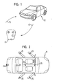
- the remote control system serves as a keyless one Access system and comprises a mobile transceiver 21, the is also referred to as a mobile transceiver and that the user of one Motor vehicle 11 carries.
- the transceiver 21 works with an in the vehicle 11 integrated arrangement according to the invention together, which are described in more detail below in particular in connection with FIG. 4 becomes.
- the interaction between the mobile transceiver 21 and the Vehicle-fixed arrangement of the access system are between a in following explained communication unit on the vehicle and transmit signals to the transceiver 21 by means of electromagnetic waves, which are characterized by certain frequencies f1 and f2.
- the signal exchange can be checked whether it is a for the respective vehicle 11 is authorized transceiver 21 with which for example, the vehicle 11 can be opened remotely without a key can and / or other remote-controlled vehicle functions activated or can be deactivated.
- the signal transmission from the vehicle frequency f2 used for the transceiver is z. B. 125 kHz.
- the frequency f1 used for signal transmission from the transceiver to the vehicle is, for example, 433 MHz.
- the vehicle 11 can use a plurality of the communication units mentioned include. These are preferably such as that Vehicle 11 distributed that one is from any Approaching the vehicle 11 or at any point in the Vehicle 11 user reliably by means of the mobile transmitting / receiving part 21 communicate with the access system of the vehicle 11 can.
- FIG. 2 shows several examples of the positioning of the communication units 25, namely on the rear bumper, on the trunk, on Rear seat, on the vehicle tunnel, on the dashboard or on the vehicle doors.
- the communication units 25 can within the Door panels are arranged. According to the invention, it is also possible to design the communication units 25 so compactly that they can be accommodated in the door handles.
- a central, common control unit for the communication units 25, which is basically anywhere in the vehicle 11 can be attached.
- the control unit is used on the one hand for the voltage supply of the communication units 25 and also provides the signal transmission to and from the communication units 25 is secure.
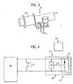
- Fig. 3 shows a ferrite antenna, as in a preferred embodiment of the invention, which is explained in more detail below with reference to FIG. 4 is used.
- the antenna 15 comprises in particular a wound coil 33 with a Ferrite core 35.
- the antenna 15 is connected to the overall arrangement via contact pins 41 connected.
- Fig. 4 shows that the transmitter unit 13 and the receiver unit 17 into one Communication unit 25 summarized and preferably in one common, compact housing are arranged.
- Comprising a coil with a ferrite core and a trimming capacitor Antenna 15 is parallel to one in the form of an integrated circuit (IC) provided proximity sensor 19 between two electrical lines 29, 31 switched.
- IC integrated circuit
- a commercially available sensor can be used as the proximity sensor 19 IC module can be used.
- the two lines 29, 31 in the form of a twisted double line or twisted pair line 27 is provided.
- the double line 27 met multiple functions.
- 23 are generated in the control unit Transmit signals via the double line 27 to the antenna circuit 15 transmitted to emit signals to the mobile transceiver 21.
- the double line 27 to digital output signals of the Proximity sensor 19 when a person approaches the vehicle generated to be transmitted to the control unit 23.
- the double line 27 for supplying power to the communication unit 25 by the control unit 23.
- the twisted pair line 27 thus represents a multi-purpose connection, which allows only a single signal and supply path between to provide the control unit 23 and the communication unit 25.
- the control unit 23 can e.g. B. arranged in a door panel become.
- a Connecting line 43 is provided, via which the antenna 15 to the Input of the proximity sensor 19 is connected. So the antenna serves 15 not only to emit signals, but also at the same time as the receiving electrode of the proximity sensor 19. Alternatively, a separate receiving electrode is provided for the sensor 19 and basically in any place inside or outside the Communication unit 25 containing housing can be arranged.
- the invention in the remote control system a high degree of integration of the components as well as advantageous Synergy effects achieved.
- the remote control system can therefore be simple be built and manufactured inexpensively. It also reduces weight achieved and the possibility of a higher degree of miniaturization created.
Abstract
Description
Die Erfindung betrifft eine Anordnung für ein Fernbedienungssystem, insbesondere schlüsselloses Zugangssystem, für Kraftfahrzeuge, mit zumindest einer Sendeeinheit und wenigstens einer Empfangseinheit, die zur drahtlosen Kommunikation mit einem mobilen Sende-/Empfangsteil ausgebildet sind.The invention relates to an arrangement for a remote control system, in particular keyless entry system, for motor vehicles, with at least a transmitting unit and at least one receiving unit which for wireless communication with a mobile transceiver are.
Fernbedienungssysteme wie z.B. schlüssellose Zugangssysteme für Kraftfahrzeuge sind grundsätzlich bekannt. Fahrzeugseitig ist der komplizierte Aufbau der bekannten Systeme problematisch. Es muß auch neben der Versorgung der Sendeeinheit und der Empfangseinheit außerdem für die Übertragung von Sendesignalen und Empfangssignalen an entsprechende Steuereinrichtungen gesorgt werden.Remote control systems such as keyless entry systems for motor vehicles are generally known. The vehicle side is the complicated one Structure of the known systems problematic. In addition to the Supply of the transmitter unit and the receiver unit also for Transmission of transmission signals and reception signals to corresponding ones Control devices are taken care of.
Es ist das der Erfindung zugrundeliegende Problem (Aufgabe), eine Anordnung für ein Fernbedienungssystem der eingangs genannten Art zu schaffen, das bei zuverlässiger Funktionsweise möglichst einfach aufgebaut ist.It is the problem (object) on which the invention is based, an arrangement for a remote control system of the type mentioned create that as simple as possible with reliable operation is.
Die Lösung dieser Aufgabe erfolgt durch die Merkmale des Anspruchs 1 und insbesondere dadurch, daß eine gemeinsame Steuereinheit für die Sendeeinheit und die Empfangseinheit vorgesehen ist, wobei die Sendeeinheit und die Empfangseinheit zu einer Kommunikationseinheit zusammengefaßt sind, die mit der Steuereinheit durch einen Signal- und Versorgungspfad verbunden ist, der zur Übertragung von Sendesignalen an die Kommunikationseinheit und von Empfangssignalen an die Steuereinheit sowie zur Spannungsversorgung der Kommunikationseinheit ausgebildet ist.This object is achieved by the features of claim 1 and in particular in that a common control unit for the Transmitting unit and the receiving unit is provided, the transmitting unit and the receiving unit combined to form a communication unit are with the control unit by a signal and Supply path is connected to the transmission of transmission signals to the communication unit and of reception signals to the control unit as well as for supplying power to the communication unit is.
Erfindungsgemäß sind die Sendeeinheit und die Empfangseinheit zu einer Kommunikationseinheit zusammengefaßt. Hierdurch wird die Möglichkeit zur gemeinsamen Nutzung von Bauteilen sowie zur Vereinfachung der Versorgung und Signalübertragung eröffnet. Außerdem können die Sendeeinheit und die Empfangseinheit in einem gemeinsamen Gehäuse untergebracht werden, wodurch eine kompakte Kommunikationseinheit mit geringen Abmessungen und somit minimalem Platzbedarf geschaffen werden kann, die an grundsätzlich beliebigen Stellen eines Kraftfahrzeuges auch bei beengten Platzverhältnissen angeordnet werden kann. Der Aufbau insbesondere eines schlüssellosen Zugangssystems wird erfindungsgemäß ferner dadurch vereinfacht, daß zum einen eine gemeinsame Steuereinheit für die Kommunikationseinheit und damit für den Sender und den Empfänger vorgesehen ist. Zum anderen ist erfindungsgemäß ein Signal- und Versorgungspfad zwischen der zentralen Steuereinheit und der Kommunikationseinheit vorgesehen, welcher derart ausgebildet ist, daß über ihn nicht nur der Sendeeinheit die jeweiligen Sendesignale zugeführt und von der Empfangseinheit empfangene Signale an die gemeinsame Steuereinheit weitergeleitet werden können. Vielmehr ist die Verbindung erfindungsgemäß außerdem in der Lage, gleichzeitig die Spannungsversorgung der Kommunikationseinheit und damit des Senders und des Empfängers sicherzustellen. Durch diese erfindungsgemäße Mehrzweckleitung und die Zusammenfassung des Senders und Empfängers zu einer Kommunikationseinheit wird auf einfache Weise ein hoher Integrationsgrad für die das Fernbedienungs- bzw. Zugangssystem bildenden Komponenten erzielt. Der Signal- und Versorgungspfad kann dabei die einzige erforderliche Verbindung zwischen der Steuereinheit und der Kommunikationseinheit sein.According to the invention, the transmitting unit and the receiving unit are one Communication unit summarized. This will give you the opportunity to share components and to simplify the Supply and signal transmission opened. In addition, the transmitter unit and the receiving unit housed in a common housing be, creating a compact communication unit with small dimensions and thus minimal space requirements can be created can, in principle anywhere in a motor vehicle can also be arranged in confined spaces. The structure In particular, a keyless entry system is invented further simplified in that, on the one hand, a common control unit for the communication unit and thus for the transmitter and the recipient is provided. On the other hand, according to the invention, a signal and supply path between the central control unit and the Communication unit provided, which is designed such that The respective transmission signals are not only supplied to the transmission unit via it and signals received by the receiving unit to the common one Control unit can be forwarded. Rather, the connection according to the invention also capable of simultaneously supplying power the communication unit and thus the transmitter and the Ensure the recipient. Through this multi-purpose line according to the invention and combining the transmitter and receiver into one Communication unit becomes a high degree of integration in a simple manner for the components forming the remote control or access system achieved. The signal and supply path can be the only one required connection between the control unit and the communication unit his.
In einer besonders bevorzugten praktischen Ausführung der Erfindung ist vorgesehen, daß der Signal- und Versorgungspfad von einem einzigen Paar elektrischer Leitungen gebildet wird.In a particularly preferred practical embodiment of the invention provided that the signal and supply path from a single Pair of electrical lines is formed.
Vorzugsweise handelt es sich bei dem Leitungspaar um eine verdrillte Doppelleitung, die auch als twisted pair oder twisted pair-Leitung bezeichnet wird.The pair of lines is preferably a twisted pair Double line, also known as a twisted pair or twisted pair line becomes.
Eine weitere praktische Ausgestaltung der Erfindung schlägt vor, daß die Sendeeinheit eine Antenne umfaßt, die insbesondere als eine Ferritantenne ausgebildet ist.Another practical embodiment of the invention proposes that the Transmitting unit comprises an antenna, in particular as a ferrite antenna is trained.
Des weiteren ist vorzugsweise vorgesehen, daß die Empfangseinheit einen Näherungssensor umfaßt.Furthermore, it is preferably provided that the receiving unit has a Proximity sensor includes.
In einem besonders bevorzugten Ausführungsbeispiel ist eine Antenne der Sendeeinheit gleichzeitig als ein Empfangselement und insbesondere als Empfangselektrode des Näherungssensors vorgesehen.In a particularly preferred embodiment, an antenna is the Transmitting unit simultaneously as a receiving element and in particular as Receiving electrode of the proximity sensor provided.
Hierdurch wird in vorteilhafter Weise ein Synergieeffekt erzielt, indem ein Bauteil, in diesem Fall die Antenne, ein Bestandteil sowohl der Sendeeinheit als auch der Empfangseinheit ist. Dieses bevorzugte Ausführungsbeispiel zeichnet sich folglich nicht nur durch eine hohen Integrationsgrad der Komponenten, sondern überdies durch die Ausnutzung von Synergieeffekten aus.In this way, a synergy effect is advantageously achieved by a Component, in this case the antenna, a component of both the transmitter unit as well as the receiving unit. This preferred embodiment is therefore not only characterized by a high degree of integration of the components, but also by exploiting synergy effects out.
Vorzugsweise ist dabei die Antenne an den Eingang des Näherungssensors angeschlossen, der bevorzugt in Form eines integrierten Schaltkreises (IC) vorgesehen ist. Derartige Sensor-ICs sind im Handel erhältlich. Die Erfindung ermöglicht somit insbesondere den Aufbau eines einfachen sowie gleichzeitig kostengünstigen Fernbedienungssystem.The antenna is preferably at the input of the proximity sensor connected, preferably in the form of an integrated circuit (IC) is provided. Such sensor ICs are commercially available. The invention thus enables in particular the construction of a simple and at the same time inexpensive remote control system.
Des weiteren kann gemäß einer bevorzugten Ausgestaltung der Erfindung durch die Integration der Empfangs- oder Näherungssensorelektronik in die Sende- oder Antenneneinheit eine Diagnose des Signal- und Versorgungspfades erfolgen und insbesondere ein Leitungsbruch nachgewiesen werden.Furthermore, according to a preferred embodiment of the invention by integrating the receiver or proximity sensor electronics in the transmitter or antenna unit diagnoses the signal and supply path take place and in particular a wire break is proven become.
Ferner ist die den Sender und den Empfänger umfassende Kommunikationseinheit vorzugsweise so ausgebildet, daß sie in einer Innenverkleidung, insbesondere einer Tür, und/oder einem Türgriff eines Kraftfahrzeugs untergebracht werden kann. Weitere Unterbringungsmöglichkeiten stellen insbesondere eine Stoßstange, die Armaturentafel, eine Kofferraumverkleidung bzw. der Griff der Kofferraumklappe, die Rücksitze oder der Tunnel des Kraftfahrzeugs dar.Furthermore, the communication unit comprising the transmitter and the receiver preferably designed so that they are in an inner lining, in particular a door and / or a door handle of a motor vehicle can be accommodated. Provide other accommodation options in particular a bumper, the dashboard, a trunk lining or the handle of the trunk lid, the rear seats or the tunnel of the motor vehicle.
Die Erfindung betrifft außerdem ein Fernbedienungssystem für Kraftfahrzeuge, das wenigstens eine Anordnung gemäß der Erfindung umfaßt, wie sie vorstehend beschrieben worden ist. The invention also relates to a remote control system for motor vehicles, which comprises at least one arrangement according to the invention, such as it has been described above.
Des weiteren betrifft die Erfindung ein Kraftfahrzeug mit einem derartigen Fernbedienungssystem gemäß der Erfindung.Furthermore, the invention relates to a motor vehicle with such a Remote control system according to the invention.
Vorteilhafte Ausführungsformen der Erfindung sind auch in den Unteransprüchen, der Beschreibung sowie der Zeichnung angegeben.Advantageous embodiments of the invention are also in the subclaims, the description and the drawing.
Die Erfindung wird im folgenden beispielhaft unter Bezugnahme auf die Zeichnung beschrieben. Es zeigen:
- Fig. 1
- ein Schaubild zur Erläuterung des Zusammenspiels zwischen einem mobilen Sende-/Empfangsteil und einem Kraftfahrzeug mit einem erfindungsgemäßen Fernbedienungssystem,
- Fig. 2
- ein Schaubild zur Erläuterung von Anordnungsmöglichkeiten für Kommunikationseinheiten des erfindungsgemäßen Fernbedienungssystems,
- Fig. 3
- eine Ansicht eines Ausführungsbeispiels einer in Verbindung mit der Erfindung einsetzbaren Antenne, und
- Fig. 4
- eine Ausführungsform einer Schaltungsanordnung für das erfindungsgemäße Fernbedienungssystem.
- Fig. 1
- 2 shows a diagram for explaining the interaction between a mobile transmitting / receiving part and a motor vehicle with a remote control system according to the invention,
- Fig. 2
- 1 shows a diagram for explaining arrangement options for communication units of the remote control system according to the invention,
- Fig. 3
- a view of an embodiment of an antenna usable in connection with the invention, and
- Fig. 4
- an embodiment of a circuit arrangement for the remote control system according to the invention.
Das erfindungsgemäße Fernbedienungssystem dient als schlüsselloses
Zugangssystem und umfaßt ein mobiles Sende-/Empfangsteil 21, das
auch als mobiler Transceiver bezeichnet wird und das der Benutzer eines
Kraftfahrzeuges 11 bei sich trägt. Der Transceiver 21 wirkt mit einer in
das Fahrzeug 11 integrierten Anordnung gemäß der Erfindung zusammen,
die im folgenden insbesondere in Verbindung mit Fig. 4 näher beschrieben
wird. Beim Zusammenspiel zwischen dem mobilen Transceiver 21 und der
fahrzeugfesten Anordnung des Zugangssystems werden zwischen einer im
folgenden näher erläuterten Kommunikationseinheit am Fahrzeug und
dem Transceiver 21 mittels elektromagnetischer Wellen Signale übertragen,
die sich durch bestimmte Frequenzen f1 und f2 auszeichnen. Durch
diesen Signalaustausch kann überprüft werden, ob es sich um einen für
das jeweilige Fahrzeug 11 berechtigten Transceiver 21 handelt, mit dem
beispielsweise das Fahrzeug 11 schlüssellos aus der Ferne geöffnet werden
kann und /oder andere fernbetätigbare Fahrzeugfunktionen aktiviert
oder deaktiviert werden können. Die zur Signalübertragung vom Fahrzeug
zum Transceiver verwendete Frequenz f2 beträgt z. B. 125 kHz. Die Frequenz
f1, die zur Signalübertragung vom Transceiver zum Fahrzeug verwendet
wird, beträgt beispielsweise 433 MHz.The remote control system according to the invention serves as a keyless one
Access system and comprises a
Wie Fig. 2 zeigt, kann das Fahrzeug 11 eine Vielzahl der erwähnten Kommunikationseinheiten
umfassen. Diese sind vorzugsweise derart über das
Fahrzeug 11 verteilt untergebracht, daß ein sich aus einer beliebigen
Richtung dem Fahrzeug 11 nähernder oder an einer beliebigen Stelle im
Fahrzeug 11 befindlicher Benutzer zuverlässig mittels des mobilen Sende-/Empfangsteils
21 mit dem Zugangssystem des Fahrzeugs 11 kommunizieren
kann.As shown in FIG. 2, the
Fig. 2 zeigt mehrere Beispiele für die Positionierung der Kommunikationseinheiten
25, und zwar an der hinteren Stoßstange, am Kofferraum, am
Rücksitz, am Fahrzeugtunnel, an der Armaturentafel oder an den Fahrzeugtüren.
Dabei können die Kommunikationseinheiten 25 innerhalb der
Türverkleidungen angeordnet werden. Es ist erfindungsgemäß auch möglich,
die Kommunikationseinheiten 25 derart kompakt auszugestalten,
daß sie in den Türgriffen untergebracht werden können. Nicht dargestellt
in Fig. 2 ist eine zentrale, gemeinsame Steuereinheit für die Kommunikationseinheiten
25, die grundsätzlich an einer beliebigen Stelle im Fahrzeug
11 angebracht werden kann. Die Steuereinheit dient zum einen der Spannungsversorgung
der Kommunikationseinheiten 25 und stellt außerdem
die Signalübertragung zu und von den Kommunikationseinheiten 25 sicher.2 shows several examples of the positioning of the
Fig. 3 zeigt eine Ferritantenne, wie sie in einem bevorzugten Ausführungsbeispiel der Erfindung, das im folgenden näher anhand von Fig. 4 erläutert wird, zum Einsatz kommt.Fig. 3 shows a ferrite antenna, as in a preferred embodiment of the invention, which is explained in more detail below with reference to FIG. 4 is used.
Die Antenne 15 umfaßt insbesondere eine gewickelte Spule 33 mit einem
Ferritkern 35. Über Kontaktstifte 41 wird die Antenne 15 an die Gesamtanordnung
angeschlossen.The
Fig. 4 zeigt, daß die Sendeeinheit 13 und die Empfangseinheit 17 zu einer
Kommunikationseinheit 25 zusammengefaßt und vorzugsweise in einem
gemeinsamen, kompakten Gehäuse angeordnet sind.Fig. 4 shows that the
Die eine Spule mit Ferritkern sowie einen Trimmkondensator umfassende
Antenne 15 ist parallel zu einem in Form eines integrierten Schaltkreises
(IC) vorgesehenen Näherungssensor 19 zwischen zwei elektrische Leitungen
29, 31 geschaltet. Als Näherungssensor 19 kann ein handelsüblicher
IC-Baustein verwendet werden. Comprising a coil with a ferrite core and a trimming
Zur Verbindung der Kommunikationseinheit 25 mit einer Steuereinheit 23
sind die beiden Leitungen 29, 31 in Form einer verdrillten Doppelleitung
oder twisted pair-Leitung 27 vorgesehen. Die Doppelleitung 27 erfüllt
mehrere Funktionen. Zum einen werden in der Steuereinheit 23 generierte
Sendesignale über die Doppelleitung 27 an die Antennenschaltung 15
übermittelt, um Signale an den mobilen Transceiver 21 abzustrahlen. Des
weiteren dient die Doppelleitung 27 dazu, digitale Ausgangssignale des
Näherungssensors 19, die bei Annäherung einer Person an das Fahrzeug
erzeugt werden, an die Steuereinheit 23 zu übertragen. Außerdem dient
die Doppelleitung 27 zur Spannungsversorgung der Kommunikationseinheit
25 durch die Steuereinheit 23.For connecting the
Die twisted pair-Leitung 27 stellt somit eine Mehrzweckverbindung dar,
die es gestattet, lediglich einen einzigen Signal- und Versorgungspfad zwischen
der Steuereinheit 23 und der Kommunikationseinheit 25 vorzusehen.
Die Steuereinheit 23 kann z. B. in einer Türverkleidung angeordnet
werden.The
Zwischen der Antenne 15 und dem Näherungssensor 19 ist ferner eine
Verbindungsleitung 43 vorgesehen, über welche die Antenne 15 an den
Eingang des Näherungssensors 19 angeschlossen ist. Somit dient die Antenne
15 nicht nur dazu, Signale abzustrahlen, sondern außerdem gleichzeitig
als Empfangselektrode des Näherungssensors 19. Alternativ kann
eine separate Empfangselektrode für den Sensor 19 vorgesehen und
grundsätzlich an einem beliebigen Ort innerhalb oder außerhalb des die
Kommunikationseinheit 25 enthaltenden Gehäuses angeordnet werden. Between the
Auf diese Weise werden durch die Erfindung in dem Ferndedienungssystem ein hoher Integrationsgrad der Komponenten sowie vorteilhafte Synergieeffekte erzielt. Das Fernbedienungssystem kann folglich einfach aufgebaut und kostengünstig hergestellt werden. Ferner wird eine Gewichtsreduzierung erreicht und die Möglichkeit zu einem höheren Miniaturisierungsgrad geschaffen. In this way, the invention in the remote control system a high degree of integration of the components as well as advantageous Synergy effects achieved. The remote control system can therefore be simple be built and manufactured inexpensively. It also reduces weight achieved and the possibility of a higher degree of miniaturization created.
- 1111
- Kraftfahrzeugmotor vehicle
- 1313
- Sendeeinheittransmission unit
- 1515
- Antenneantenna
- 1717
- Empfangseinheitreceiver unit
- 1919
- NäherungssensorProximity sensor
- 2121
- mobiles Sende-/Empfangsteilmobile transmitter / receiver unit
- 2323
- Steuereinheitcontrol unit
- 2525
- Kommunikationseinheitcommunication unit
- 2727
- Signal- und Versorgungspfad, LeitungspaarSignal and supply path, pair of lines
- 2929
- elektrische Leitungelectrical line
- 3131
- elektrische Leitungelectrical line
- 3333
- SpuleKitchen sink
- 3535
- Ferritkernferrite
- 4141
- Kontaktstiftpin
- 4343
- Verbindungsleitungconnecting line
Claims (14)
dadurch gekennzeichnet, daß der Signal- und Versorgungspfad (27) von einem einzigen Paar elektrischer Leitungen (29, 31) gebildet ist, die vorzugsweise in Form einer verdrillten Doppelleitung (twisted-pair-Leitung) vorgesehen sind.Arrangement according to claim 1,
characterized in that the signal and supply path (27) is formed by a single pair of electrical lines (29, 31), which are preferably provided in the form of a twisted-pair line (twisted-pair line).
dadurch gekennzeichnet, daß die Sendeeinheit (13) eine Antenne (15) umfaßt, insbesondere eine Ferritantenne. Arrangement according to claim 1 or 2,
characterized in that the transmission unit (13) comprises an antenna (15), in particular a ferrite antenna.
dadurch gekennzeichnet, daß die Empfangseinheit (17) einen Näherungssensor (19) umfaßt.Arrangement according to one of the preceding claims,
characterized in that the receiving unit (17) comprises a proximity sensor (19).
dadurch gekennzeichnet, daß wenigstens ein Bauteil (15) der Kommunikationseinheit (25) ein Bestandteil sowohl der Sendeeinheit (13) als auch der Empfangseinheit (17) ist.Arrangement according to one of the preceding claims,
characterized in that at least one component (15) of the communication unit (25) is a component of both the transmitting unit (13) and the receiving unit (17).
dadurch gekennzeichnet, daß ein gemeinsames Bauteil der Sendeeinheit (13) und der Empfangseinheit (17) eine Antenne (15) ist.Arrangement according to one of the preceding claims,
characterized in that a common component of the transmitter unit (13) and the receiver unit (17) is an antenna (15).
dadurch gekennzeichnet, daß eine Antenne (15) der Sendeeinheit (13) gleichzeitig als ein Empfangselement, insbesondere als eine Empfangselektrode, der Empfangseinheit (17) vorgesehen ist.Arrangement according to one of the preceding claims,
characterized in that an antenna (15) of the transmitting unit (13) is simultaneously provided as a receiving element, in particular as a receiving electrode, of the receiving unit (17).
dadurch gekennzeichnet, daß die Antenne (15) an den Eingang eines Näherungssensors (19) der Empfangseinheit (17) angeschlossen ist. Arrangement according to claim 7,
characterized in that the antenna (15) is connected to the input of a proximity sensor (19) of the receiving unit (17).
dadurch gekennzeichnet, daß die Kommunikationseinheit (25) zur Diagnose des Signal- und Versorgungspfades (27) und insbesondere zum Nachweis eines Leitungsbruchs ausgebildet ist.Arrangement according to one of the preceding claims,
characterized in that the communication unit (25) is designed to diagnose the signal and supply path (27) and in particular to detect a line break.
dadurch gekennzeichnet, daß die Kommunikationseinheit (25) zur Unterbringung in einer Innenverkleidung, insbesondere einer Tür, und/oder in einem Türgriff eines Kraftfahrzeuges (11) ausgebildet ist.Arrangement according to one of the preceding claims,
characterized in that the communication unit (25) is designed for accommodation in an interior lining, in particular a door, and / or in a door handle of a motor vehicle (11).
dadurch gekennzeichnet, daß es mehrere Kommunikationseinheiten (25) umfaßt, die mit einer gemeinsamen Steuereinheit (23) verbunden sind.System according to claim 11,
characterized in that it comprises a plurality of communication units (25) connected to a common control unit (23).
dadurch gekennzeichnet, daß mehrere über das Kraftfahrzeug (11) verteilt angeordnete Kommunikationseinheiten (25) vorgesehen sind, die mit einer gemeinsamen Steuereinheit (23) verbunden sind.Motor vehicle according to claim 13,
characterized in that a plurality of communication units (25) are provided distributed over the motor vehicle (11) and are connected to a common control unit (23).
Applications Claiming Priority (2)
| Application Number | Priority Date | Filing Date | Title |
|---|---|---|---|
| DE10060431 | 2000-12-05 | ||
| DE2000160431 DE10060431A1 (en) | 2000-12-05 | 2000-12-05 | Arrangement for a remote control system on motor vehicles |
Publications (2)
| Publication Number | Publication Date |
|---|---|
| EP1213687A1 true EP1213687A1 (en) | 2002-06-12 |
| EP1213687B1 EP1213687B1 (en) | 2009-03-25 |
Family
ID=7665874
Family Applications (1)
| Application Number | Title | Priority Date | Filing Date |
|---|---|---|---|
| EP20010128938 Expired - Lifetime EP1213687B1 (en) | 2000-12-05 | 2001-12-05 | Arrangement for remote control system for motor vehicles |
Country Status (2)
| Country | Link |
|---|---|
| EP (1) | EP1213687B1 (en) |
| DE (2) | DE10060431A1 (en) |
Cited By (4)
| Publication number | Priority date | Publication date | Assignee | Title |
|---|---|---|---|---|
| WO2012080328A1 (en) * | 2010-12-15 | 2012-06-21 | Valeo Securite Habitacle | Electronic communication module for locking/unlocking a movable panel of a motor vehicle, associated control central processing unit, and hands-free access system |
| WO2014012658A1 (en) * | 2012-07-16 | 2014-01-23 | Brose Fahrzeugteile Gmbh & Co. Kommanditgesellschaft, Hallstadt | Sensor device for a vehicle |
| CN103953234A (en) * | 2014-05-13 | 2014-07-30 | 华域汽车系统股份有限公司 | Vehicle keyless door lock system with connecting line shared by switching circuit and resonance circuit |
| EP2685435A3 (en) * | 2012-07-10 | 2017-06-07 | Aisin Seiki Kabushiki Kaisha | Antenna drive apparatus |
Citations (5)
| Publication number | Priority date | Publication date | Assignee | Title |
|---|---|---|---|---|
| EP0482965A1 (en) * | 1990-10-24 | 1992-04-29 | Regie Nationale Des Usines Renault S.A. | Method and device for testing a dataprocessing module and its application in vehicle electronics |
| US5134392A (en) * | 1987-06-16 | 1992-07-28 | Nissan Motor Company, Limited | Keyless entry system for locking and unlocking a vehicular lock device by a pocket portable radio signal transmitter and antenna arrangement therefor |
| EP0800094A1 (en) * | 1996-04-02 | 1997-10-08 | Ford Motor Company | Circuit for detecting a transponder |
| EP0848123A2 (en) * | 1996-10-10 | 1998-06-17 | Texas Instruments Deutschland Gmbh | A remote keyless entry system |
| DE19835155A1 (en) * | 1998-08-04 | 2000-02-24 | Bosch Gmbh Robert | Device and method for an authorization request in a motor vehicle |
-
2000
- 2000-12-05 DE DE2000160431 patent/DE10060431A1/en not_active Withdrawn
-
2001
- 2001-12-05 DE DE50114788T patent/DE50114788D1/en not_active Expired - Lifetime
- 2001-12-05 EP EP20010128938 patent/EP1213687B1/en not_active Expired - Lifetime
Patent Citations (5)
| Publication number | Priority date | Publication date | Assignee | Title |
|---|---|---|---|---|
| US5134392A (en) * | 1987-06-16 | 1992-07-28 | Nissan Motor Company, Limited | Keyless entry system for locking and unlocking a vehicular lock device by a pocket portable radio signal transmitter and antenna arrangement therefor |
| EP0482965A1 (en) * | 1990-10-24 | 1992-04-29 | Regie Nationale Des Usines Renault S.A. | Method and device for testing a dataprocessing module and its application in vehicle electronics |
| EP0800094A1 (en) * | 1996-04-02 | 1997-10-08 | Ford Motor Company | Circuit for detecting a transponder |
| EP0848123A2 (en) * | 1996-10-10 | 1998-06-17 | Texas Instruments Deutschland Gmbh | A remote keyless entry system |
| DE19835155A1 (en) * | 1998-08-04 | 2000-02-24 | Bosch Gmbh Robert | Device and method for an authorization request in a motor vehicle |
Cited By (7)
| Publication number | Priority date | Publication date | Assignee | Title |
|---|---|---|---|---|
| WO2012080328A1 (en) * | 2010-12-15 | 2012-06-21 | Valeo Securite Habitacle | Electronic communication module for locking/unlocking a movable panel of a motor vehicle, associated control central processing unit, and hands-free access system |
| FR2969430A1 (en) * | 2010-12-15 | 2012-06-22 | Valeo Securite Habitacle | ELECTRONIC COMMUNICATION MODULE FOR LOCKING / UNLOCKING A MOTOR VEHICLE OPENER, CONTROLLED CONTROL UNIT AND HANDS-FREE ACCESS SYSTEM |
| CN103430221A (en) * | 2010-12-15 | 2013-12-04 | 法雷奥安全座舱公司 | Electronic communication module for locking/unlocking a movable panel of a motor vehicle, associated control central processing unit, and hands-free access system |
| US9996994B2 (en) | 2010-12-15 | 2018-06-12 | Valeo Securite Habitacle | Electronic communication module for locking/unlocking a movable panel of a motor vehicle, associated control central processing unit, and hands-free access system |
| EP2685435A3 (en) * | 2012-07-10 | 2017-06-07 | Aisin Seiki Kabushiki Kaisha | Antenna drive apparatus |
| WO2014012658A1 (en) * | 2012-07-16 | 2014-01-23 | Brose Fahrzeugteile Gmbh & Co. Kommanditgesellschaft, Hallstadt | Sensor device for a vehicle |
| CN103953234A (en) * | 2014-05-13 | 2014-07-30 | 华域汽车系统股份有限公司 | Vehicle keyless door lock system with connecting line shared by switching circuit and resonance circuit |
Also Published As
| Publication number | Publication date |
|---|---|
| DE10060431A1 (en) | 2002-06-20 |
| EP1213687B1 (en) | 2009-03-25 |
| DE50114788D1 (en) | 2009-05-07 |
Similar Documents
| Publication | Publication Date | Title |
|---|---|---|
| EP2637903B1 (en) | Locking system especially for a vehicle | |
| DE102017110145A1 (en) | Vehicle door handle with antenna arrangement | |
| DE3627193A1 (en) | ANTENNA FOR SENDING AND / OR RECEIVING HIGH FREQUENCY WAVES, ESPECIALLY FOR KEYLESS ACCESS SYSTEMS ON VEHICLES | |
| DE4240426C2 (en) | Method for recognizing a portable, key-side system part of a central locking system for motor vehicles enclosed in the vehicle interior | |
| EP0961418A2 (en) | Radio system for telecontrol functions in standing vehicles | |
| EP1723615B1 (en) | Inductive component for an electronic key | |
| DE10317658A1 (en) | Position display method e.g. for locating stolen vehicle, involves position recognition of a code giver, in particular portable code giver with position of code giver obtained by means of antenna array | |
| EP1213687B1 (en) | Arrangement for remote control system for motor vehicles | |
| EP1083280B1 (en) | Keyless actuating and/or locking device, particularly for vehicles | |
| DE19915294C2 (en) | Bus system | |
| EP1447878A1 (en) | Antenna for a radio central locking system | |
| DE102015205038B4 (en) | Reception circuit, in particular for installation in a vehicle access and start system (PASE) | |
| EP1014479B1 (en) | Antenna arrangement for the keyless use of a vehicle | |
| DE60302004T2 (en) | Vehicle with a device for transmitting signals | |
| DE10063252A1 (en) | Radio remote control system, in particular for motor vehicles | |
| EP2825424B1 (en) | Locking system, especially for a motor vehicle | |
| DE102020126533A1 (en) | UWB module unit for a vehicle | |
| EP1873722A1 (en) | Access control system | |
| DE60211419T2 (en) | Start authorization system of a motor vehicle | |
| EP1703472A1 (en) | Access control system | |
| EP1173648B1 (en) | Electronic control device in a motor vehicle for at least one garage door opener | |
| EP1431928B1 (en) | Access control installation including an access side's control device and a user identification device having transceivers for bi-directional communication | |
| DE10209133A1 (en) | Radio key for remote locking of motor vehicle uses key shaft and/or metal part of housing made as transmission antenna in order to increase transmission range of radio key | |
| DE60221532T2 (en) | IDENTIFICATION DEVICE FOR A MOTOR VEHICLE | |
| DE10222798A1 (en) | System for a motor vehicle |
Legal Events
| Date | Code | Title | Description |
|---|---|---|---|
| PUAI | Public reference made under article 153(3) epc to a published international application that has entered the european phase |
Free format text: ORIGINAL CODE: 0009012 |
|
| AK | Designated contracting states |
Kind code of ref document: A1 Designated state(s): AT BE CH CY DE DK ES FI FR GB GR IE IT LI LU MC NL PT SE TR |
|
| AX | Request for extension of the european patent |
Free format text: AL;LT;LV;MK;RO;SI |
|
| 17P | Request for examination filed |
Effective date: 20020711 |
|
| AKX | Designation fees paid |
Designated state(s): DE FR GB IT SE |
|
| 17Q | First examination report despatched |
Effective date: 20070704 |
|
| GRAP | Despatch of communication of intention to grant a patent |
Free format text: ORIGINAL CODE: EPIDOSNIGR1 |
|
| GRAS | Grant fee paid |
Free format text: ORIGINAL CODE: EPIDOSNIGR3 |
|
| GRAA | (expected) grant |
Free format text: ORIGINAL CODE: 0009210 |
|
| AK | Designated contracting states |
Kind code of ref document: B1 Designated state(s): DE FR GB IT SE |
|
| REG | Reference to a national code |
Ref country code: GB Ref legal event code: FG4D Free format text: NOT ENGLISH |
|
| REF | Corresponds to: |
Ref document number: 50114788 Country of ref document: DE Date of ref document: 20090507 Kind code of ref document: P |
|
| PG25 | Lapsed in a contracting state [announced via postgrant information from national office to epo] |
Ref country code: SE Free format text: LAPSE BECAUSE OF FAILURE TO SUBMIT A TRANSLATION OF THE DESCRIPTION OR TO PAY THE FEE WITHIN THE PRESCRIBED TIME-LIMIT Effective date: 20090625 |
|
| PLBE | No opposition filed within time limit |
Free format text: ORIGINAL CODE: 0009261 |
|
| STAA | Information on the status of an ep patent application or granted ep patent |
Free format text: STATUS: NO OPPOSITION FILED WITHIN TIME LIMIT |
|
| 26N | No opposition filed |
Effective date: 20091229 |
|
| GBPC | Gb: european patent ceased through non-payment of renewal fee |
Effective date: 20091205 |
|
| PG25 | Lapsed in a contracting state [announced via postgrant information from national office to epo] |
Ref country code: GB Free format text: LAPSE BECAUSE OF NON-PAYMENT OF DUE FEES Effective date: 20091205 |
|
| REG | Reference to a national code |
Ref country code: FR Ref legal event code: TP Owner name: DELPHI INTERNATIONAL OPERATIONS LUXEMBOURG S.A, LU Effective date: 20131218 |
|
| REG | Reference to a national code |
Ref country code: DE Ref legal event code: R082 Ref document number: 50114788 Country of ref document: DE Representative=s name: MANITZ, FINSTERWALD & PARTNER GBR, DE |
|
| REG | Reference to a national code |
Ref country code: DE Ref legal event code: R082 Ref document number: 50114788 Country of ref document: DE Representative=s name: MANITZ, FINSTERWALD & PARTNER GBR, DE Effective date: 20140409 Ref country code: DE Ref legal event code: R081 Ref document number: 50114788 Country of ref document: DE Owner name: DELPHI INTERNATIONAL OPERATIONS LUXEMBOURG S.A, LU Free format text: FORMER OWNER: DELPHI TECHNOLOGIES, INC., TROY, US Effective date: 20140409 Ref country code: DE Ref legal event code: R081 Ref document number: 50114788 Country of ref document: DE Owner name: DELPHI INTERNATIONAL OPERATIONS LUXEMBOURG S.A, LU Free format text: FORMER OWNER: DELPHI TECHNOLOGIES, INC., TROY, MICH., US Effective date: 20140409 Ref country code: DE Ref legal event code: R082 Ref document number: 50114788 Country of ref document: DE Representative=s name: MANITZ FINSTERWALD PATENTANWAELTE PARTMBB, DE Effective date: 20140409 |
|
| REG | Reference to a national code |
Ref country code: FR Ref legal event code: PLFP Year of fee payment: 15 |
|
| REG | Reference to a national code |
Ref country code: FR Ref legal event code: PLFP Year of fee payment: 16 |
|
| PG25 | Lapsed in a contracting state [announced via postgrant information from national office to epo] |
Ref country code: IT Free format text: LAPSE BECAUSE OF NON-PAYMENT OF DUE FEES Effective date: 20151205 |
|
| PG25 | Lapsed in a contracting state [announced via postgrant information from national office to epo] |
Ref country code: IT Free format text: LAPSE BECAUSE OF NON-PAYMENT OF DUE FEES Effective date: 20151205 |
|
| PGRI | Patent reinstated in contracting state [announced from national office to epo] |
Ref country code: IT Effective date: 20170710 |
|
| REG | Reference to a national code |
Ref country code: FR Ref legal event code: PLFP Year of fee payment: 17 |
|
| REG | Reference to a national code |
Ref country code: DE Ref legal event code: R081 Ref document number: 50114788 Country of ref document: DE Owner name: APTIV TECHNOLOGIES LIMITED, BB Free format text: FORMER OWNER: DELPHI INTERNATIONAL OPERATIONS LUXEMBOURG S.A R.L., 4940 HAUTCHARAGE, LU Ref country code: DE Ref legal event code: R082 Ref document number: 50114788 Country of ref document: DE Representative=s name: MANITZ FINSTERWALD PATENT- UND RECHTSANWALTSPA, DE Ref country code: DE Ref legal event code: R082 Ref document number: 50114788 Country of ref document: DE Representative=s name: MANITZ FINSTERWALD PATENTANWAELTE PARTMBB, DE Ref country code: DE Ref legal event code: R081 Ref document number: 50114788 Country of ref document: DE Owner name: APTIV TECHNOLOGIES LIMITED, BB Free format text: FORMER OWNER: DELPHI INTERNATIONAL OPERATIONS LUXEMBOURG S.A R.L., 4940 BASCHARAGE, LU |
|
| PGFP | Annual fee paid to national office [announced via postgrant information from national office to epo] |
Ref country code: DE Payment date: 20201215 Year of fee payment: 20 Ref country code: FR Payment date: 20201214 Year of fee payment: 20 |
|
| PGFP | Annual fee paid to national office [announced via postgrant information from national office to epo] |
Ref country code: IT Payment date: 20201209 Year of fee payment: 20 |
|
| REG | Reference to a national code |
Ref country code: DE Ref legal event code: R071 Ref document number: 50114788 Country of ref document: DE |