EP1213683A2 - Position and orientation determining method and apparatus and storage medium - Google Patents
Position and orientation determining method and apparatus and storage medium Download PDFInfo
- Publication number
- EP1213683A2 EP1213683A2 EP01108057A EP01108057A EP1213683A2 EP 1213683 A2 EP1213683 A2 EP 1213683A2 EP 01108057 A EP01108057 A EP 01108057A EP 01108057 A EP01108057 A EP 01108057A EP 1213683 A2 EP1213683 A2 EP 1213683A2
- Authority
- EP
- European Patent Office
- Prior art keywords
- orientation
- feature point
- parameter
- image pickup
- capture means
- Prior art date
- Legal status (The legal status is an assumption and is not a legal conclusion. Google has not performed a legal analysis and makes no representation as to the accuracy of the status listed.)
- Withdrawn
Links
Images







Classifications
-
- G—PHYSICS
- G06—COMPUTING OR CALCULATING; COUNTING
- G06T—IMAGE DATA PROCESSING OR GENERATION, IN GENERAL
- G06T7/00—Image analysis
- G06T7/70—Determining position or orientation of objects or cameras
- G06T7/73—Determining position or orientation of objects or cameras using feature-based methods
- G06T7/74—Determining position or orientation of objects or cameras using feature-based methods involving reference images or patches
Definitions
- the present invention relates to a position and orientation determination apparatus, method, and a storage medium therefor for determining the position and orientation of a capture means before performing an image process to generate a augmented picture using an image in an unreal space such as computer graphics incorporated into the real space by measuring a parameter indicating the position and orientation of capture means (image pickup means) for capturing the real space with the method other than using a captured picture, and identifying the information about a picture whose parameter has been captured.
- the present invention can also be applied to any means and method for determining the position and orientation of a capture device used for any purpose other than augmenteding the real space and another space image.
- an AR (augmented reality) system for augmenting the real space by virtual space such as computer graphics, etc.
- the position and orientation of a camera cannot be precisely measured in a method, for example, using a position and orientation sensor such as a magnetic sensor, etc., other than using a captured picture, when the real space is captured by the camera. Therefore, when a virtual object is superimposed on the real space based on the position and orientation of the camera measured by the sensor, a displayed image is often shifted from a desired position.
- an external parameter position and orientation of a camera
- a plurality of feature points (landmarks) whose positions are known in a three-dimensional array are arranged in the real space.
- the external parameter of the camera is corrected using an error between the actual position of a target landmark, in some landmarks captured by the camera and displayed on the display screen of the camera, and the position of the target landmark predicted based on the position and orientation of the camera at the time, acquired by a position and orientation sensor.
- a target landmark can be a marker such as a seal having the information of specific color or form attached to an object in the real space, or a feature point in a natural scene.
- a projective matrix from the real space (three-dimensional space) to the display screen (two-dimensional plane) of the camera is calculated by a matrix operation, and an external parameter of the camera is corrected using the obtained matrix.
- the external parameter of the camera is corrected based on the target landmark. Therefore, for example, when a virtual object is superimposed on the position at a distance from a target landmark, the object can be shifted from a desired position when it is displayed. Furthermore, since a target landmark is switched and changed when the view of the camera is changed, a correction value can be largely changed when it is switched.
- an obtained projective matrix can cause an image to be mapped with incorrect orthogonality of the coordinate axis of the original coordinate system.
- space distortion can occur depending on the detection precision of a landmark.
- the present invention has been developed to solve the above mentioned problem, and aims at correcting the parameter indicating the position and orientation of a camera by reflecting a captured landmark.
- a position and orientation determination apparatus has the following configuration.
- the position and orientation determination apparatus which identifies a parameter indicating the position and orientation of capture means for capturing a picture in a real space containing a plurality of feature points whose positions are known in a three-dimensional array
- position and orientation measurement means for measuring the position and orientation of the capture means in a method other than using a captured picture
- detection means for detecting the plurality of feature points and their positions in the two-dimensional array on the image pickup screen using the picture in the real space captured by the capture means
- prediction means for predicting the positions of the feature points in the two-dimensional array on the image pickup screen based on the position and orientation of the capture means measured by the position and orientation measurement means
- correction means for correcting the parameter indicating the position and orientation of the capture means based on the positions of the feature points on the image pickup screen of the capture means obtained by the prediction means, and based on the position of the feature points obtained by the detection means.
- the parameter indicating the position and orientation of the capture means for capturing the real space is identified by the correction means correcting
- Described first is the conventional method. That is, when there are a plurality of landmarks in the real space, the method of correcting an external parameter of a camera is corrected, using an error between the actual position of a target landmark in some landmarks captured by the camera and displayed on the display screen, and the position of the target landmark predicted based on the position and orientation of the camera obtained by a position and orientation sensor. Described below is the method of using the above mentioned method for a plurality of landmarks according to an embodiment of the present invention.
- FIG. 1 shows a type of the above mentioned conventional method.
- a point A indicates the position of a landmark predicted based on the position and orientation of a camera acquired by a position and orientation sensor.
- a point B indicates the actual position of the landmark.
- a point C indicates the position of the view of the camera.
- the positions indicated by the points A and B are the positions in the camera coordinate system, and the point C is the origin of the camera coordinate system.
- a point P indicates the position of the point A on the image pickup screen, and a point Q indicates the position of the point B on the image pickup screen. As shown in FIG.
- the coordinates of the points P and Q are (Xp, Yp) and (Xq, Yq) respectively
- the width and the height of the image pickup screen are w and h respectively
- the focal distance (distance between the point C and the image pickup screen) of the camera is d
- v1 indicates the vector from the point C to the point Q
- v2 indicates the vector from the point C to the point P
- ⁇ indicates the angle made by the vectors v1 and v2.
- v1 (Xq - w/2, Yq - h/2, -d)
- v2 (Xp - w/2, Yp - h/2, -d) the respective vectors are normalized into the vector of a size of 1 (step S702).
- indicates the size of v.
- vn1 v1/
- vn2 v2/
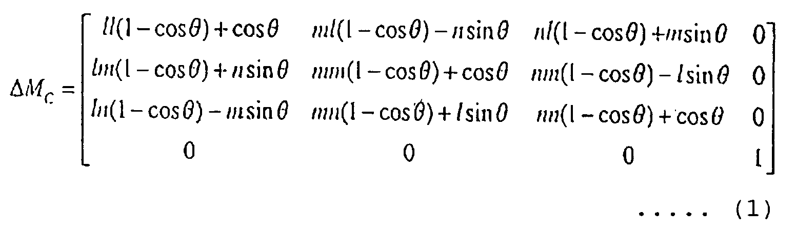
- the rotation axis When the camera is rotated, the rotation axis is orthogonal to the plane comprising the vectors v1 and v2, and is the line passing through the view point of the camera (point C).
- the direction vector of the rotation axis can be obtained by calculating the outer product of the vectors v1 and v2 (actually, the value obtained by normalizing the vectors v1 and v2) (step S703).
- vx vn1 ⁇ vn2 vx indicates the vector of the direction of the rotation axis, and its elements are (l, m, n).
- the rotation angle ⁇ is made by the vectors v1 and v2, it can be obtained as follows (actually, it is obtained by normalizing the vectors v1 and v2) (step S704).
- ⁇ arccos (vn1 ⁇ vn2)
- the correction matrix ⁇ Mc for correction made by rotating a camera can be computed as follows (step S705).
- the position and orientation (external parameter) of the camera can be corrected by multiplying the matrix indicating the position and orientation of the camera (viewing transform matrix) by the correction matrix ⁇ Mc. That is, the point P is displayed at the position of the point Q, and the predicted position of the landmark and the actual position matches on the image pickup screen.
- a vector v3 from the point A to the point B can be obtained as follows based on the similarity between the triangle CPQ and CAB(step S804).
- v3
- the correction matrix ⁇ Mc used in moving the camera in parallel can be computed as follows (step S805).
- the position and orientation (external parameter) of the camera can be corrected by multiplying the matrix indicating the position and orientation of the camera by the correction matrix ⁇ Mc.
- ⁇ Mc correction matrix
- the error above described can be reduced only around a target landmark.
- a large error can be detected around other landmarks. Therefore, according to the present embodiment, a shift is detected for all landmarks within the view of the camera, thereby reducing an error for all landmarks by using the average error.
- FIG. 2 shows a type of the correcting method according to the present embodiment.
- Points P1, P2, and P3 indicate the positions of the landmarks on the image pickup screen predicted based on the position and orientation of the camera.
- Points Q1, Q2, and Q3 indicate the actual positions of the landmarks projected on the image pickup screen.
- a representative point (Pav) for the points P1, P2, and P3, and a representative point Qav for the points Q1, Q2, and Q3 are generated, and the camera is rotated or translated in parallel such that the representative point Pav matches the point Qav.
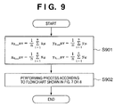
- step S902 Using the obtained representative points Pav and Qav as the points P and Q shown in FIG. 1, the correcting method by rotating a camera as described above (refer to the flowchart shown in FIG. 7) or the correcting method by translating a camera (refer to the flowchart shown in FIG. 8) are performed (step S902) to generate the correction matrix ⁇ Mc.
- a representative point (average value) of the point (the point A shown in FIG. 1) indicating the positions of the landmarks on the image pickup screen predicted based on the position and orientation of the camera is obtained. This process is performed in step S901, and the point is used as the point A shown in FIG. 1.
- the weighting coefficient wi (1 ⁇ i ⁇ n) is a coefficient value which is larger for a point closer to the center of the image pickup screen according to the present embodiment. Otherwise, for example, a value is assigned only to a target area, and the weighting coefficient wi for the area other than the target area can be set to 0.
- Qav (Xq_av, Yq_av)
- Qi (Xqi, Yqi)
- Xq_av w1 ⁇ Xq1 + w2 ⁇ Xq2 + ... + wn ⁇ Xqn
- the flowchart of the process in ⁇ Method 2> is obtained by changing the process of computing an average value in step S901 in the flowchart shown in FIG. 9 into the above mentioned process of computing an average weighting value.
- a representative point (average weighting value) of points (the point A shown in FIG. 1) indicating the positions of the landmarks predicted based on the position and orientation of the camera is obtained. This process is performed in step S901, and the obtained point is used as the point A shown in FIG. 1.
- one representative point Pav is obtained based on the positions of the landmarks on the image pickup screen predicted based on the position and orientation of the camera, and one representative point Qav is obtained based on the actual positions of the landmarks projected on the image pickup screen, thereby using the correcting method based on one landmark.
- These methods are less costly in the calculating and more efficient than the following method, but can cause the problem that the an average value is undesired when the methods are used for two landmarks which are quite different in depth.
- ⁇ Method 3> a correction is made by rotating a camera, not obtain a representative point, but obtain the rotation angle of the camera for each landmark and the direction vector of the rotation axis using above mentioned correcting method by rotating a camera, and use an average of them.
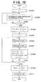
- the ⁇ Method 3> is described below by referring to the flowchart of the process shown in FIG. 10.
- Pi (1 ⁇ i ⁇ n) is a variable indicating the positions of the landmarks on the image pickup screen predicted based on the position and orientation of the camera
- Qi (1 ⁇ i ⁇ n) is a variable indicating the actual positions of the landmarks projected on the image pickup screen.
- step S1004 the direction vector vxi (1 ⁇ i ⁇ n) of the rotation axis is obtained (steps S1001 to S1003) in the method similar to the above mentioned correcting method by rotating a camera, and an average value vx_av of all vxi is obtained (step S1004).
- vx_av (vx1 + vx2 + ... + vxn)/n
- the vx_av is a direction vector of an average line of a rotation axis reflecting all Pi and Qi.
- a rotation angle for rotation on the rotation axis (line with vx_av defined as a direction vector) is obtained.
- a vector v1i from the point C to the point Qi and a plane Si passing the vx_av are obtained (step S1006).
- a vector v4i is obtained by projecting a vector v2i from the point C to the point Pi on the plane Si (step S1007).
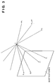
- FIG. 4 shows a type of the method of generating the vector v4i computed in each of the above mentioned processes.
- the rotation angle for matching the point Pi with the point Qi is ⁇ i
- the rotation angle ⁇ i can be obtained by the following equations by using 2i and v4i (step S1008).
- v2ni v2i/
- v4ni v4i/
- ⁇ i arccos (v2ni ⁇ v4ni)
- _mean ( ⁇ 1 + ⁇ 2 + ... + ⁇ n)/n
- the position and orientation (external parameter) of the camera can be corrected by multiplying the matrix indicating the position and orientation of the camera by the correction matrix ⁇ Mc. That is, each point Pi on the image pickup screen is displayed near each point Qi on an average, and the predicted position of the landmark matches on an average with the actual position of the landmark.
- a correction matrix can be generated with the position information about all landmarks on the image pickup screen reflected, arid the orthogonality of the coordinate system transformed by the generated correction matrix can be maintained.
- one representative point Pav is obtained based on the positions of the landmarks on the image pickup screen predicted based on the position and orientation of the camera, and one representative point Qav is obtained based on the actual positions of the landmarks projected on the image pickup screen, thereby using the correcting method based on one landmark.
- a correcting method by moving a camera in parallel is suggested, not obtain a representative point, but obtain a translation transform element of a camera for each landmark in the above mentioned correcting method by translating the camera, and the obtained element is used on an average.
- FIG. 11 is a flowchart of the process of ⁇ Method 5>.
- a correction matrix is obtained as follows (step S1105).
- an average weighting value is used.
- a correction matrix is obtained as follows using s w_mean , t w_mean , and u w_mean .
- the flowchart of the process in the ⁇ Method 6> is obtained by changing the average computation in steps S1104 in the flowchart shown in FIG. 11 into the above mentioned average weighting computation.
- a correction matrix is computed by either rotating a camera or translating it, and a correction matrix having elements of both rotation and translation cannot be obtained. Then, in method 7, the computation of a correction matrix by rotation and the computation of a correction matrix by translation are performed to compute a correction matrix by combining the above mentioned matrices.
- a correction matrix by rotation is obtained in any method above mentioned. Then, using the obtained correction matrix, the position and orientation of the camera is corrected, and the position of the landmark on the image pickup screen is obtained. Based on the obtained predicted position, a new correction matrix by translation is obtained in any method. In this method, a correction can be first made by translation, and then a correction can be made by rotation.
- the numbers of times they are performed can be determined not only predetermined times, but also based on the error between the position of a landmark on the image pickup screen predicted from the position and orientation of the camera and the position obtained by actually capturing the position.
- the method can be used by determining whether or not the error indicates a value equal to or smaller than a predetermined threshold, by determining whether or not the amount of a change in the error is equal to or smaller than a predetermined value, or by combining the determination above.
- FIG. 5 shows the rough configuration of the correcting apparatus for performing the above mentioned correcting processes according to the embodiment of the present invention.
- Reference numeral 501 denotes a head mounted display (hereinafter referred to as an HMD).
- the HMD 501 comprises a three-dimensional position and orientation sensor 501a for outputting a signal based on the position and orientation of the HMD 501 in the three-dimensional space to a position and orientation measurement unit 502 described later, a camera 501b for capturing an image of an object in the real space, and a display unit 501c for providing a picture for a user who has the HMD 501 on his or her head.
- the HMD 501 according to the present embodiment is of a video see-through type.
- the position and orientation of the HMD 501 refers to the position and orientation of the camera 501b.
- the position and orientation measurement unit 502 generates a matrix (viewing transform matrix) indicating the position and orientation of the HMD 501 based on the signal output from the three-dimensional position and orientation sensor 501a.
- Reference numeral 503 denotes a landmark detection unit.
- the landmark detection unit 503 detects a landmark from a picture captured by the camera 501b. It also detects the position of the landmark. The method of detecting them is not specified here. However, for example, a marker of a specified color is used as a landmark. Then, the specified color is detected in the picture captured by the camera 501b. As a result, the landmark and its position can be detected in the picture.
- Reference numeral 504 denotes a position and orientation correction unit.
- the position and orientation correction unit 504 computes a correction matrix using any of the above mentioned methods (any method in ⁇ Method 1> to ⁇ Method 7>) according to the position information about each landmark output from the landmark detection unit 503. Then, the matrix indicating the position and orientation of the HMD 501 output from the position and orientation measurement unit 502 is multiplied by the computed matrix. As a result, the position and orientation (external parameter) of the HMD 501 can be corrected.
- Reference numeral 505 denotes an image generation unit.
- the image generation unit 505 generates a picture of a virtual object based on the matrix corrected by the position and orientation correction unit 504, and augmenteds the picture and the picture in the real space input from the camera 501b. As a result, a picture (image) of augmented reality can be generated. It is assumed that the data relating to the virtual object is stored in the external memory. The generated image is output to the display unit 501c.
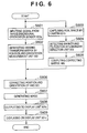
- FIG. 6 is a flowchart of the processes mainly performed by the correcting apparatus with the above mentioned configuration. Since each of the processes is described above, the detailed explanation is omitted here.
- the program code according to the flowchart shown in FIG. 6 is stored in the memory such as RAM, ROM, etc. stored in the correcting apparatus according to the present embodiment, not shown in the attached drawings, but read and executed by the CPU also not shown in the attached drawings.
- a signal indicating the position and orientation of the HMD 501 is input from the three-dimensional position and orientation sensor 501a to the position and orientation measurement unit 502 (step S601), and the position and orientation measurement unit 502 generates a viewing transform matrix indicating the position and orientation of the HMD 501 according to the input signal (step S602).
- a picture in the real space is captured by the camera 501b (step S603). The captured picture is input to the landmark detection unit 503, and the landmark and its position are detected (step S604).
- the position and orientation correction unit 504 generates a correction matrix ⁇ Mc according to the above-mentioned methods (any of ⁇ Method 1> to ⁇ Method 7>) based on the detected position of the landmark (step S605).
- the position and orientation correction unit 504 corrects the position and orientation of the HMD 501 (step S606).
- the image generation unit 505 According to the external parameter indicating the corrected position and orientation of the HMD 501, the image generation unit 505 generates a picture of a virtual object, and generates a picture of augmented reality (step S607). Then, the generated picture of augmented reality is output to a display unit 101a, (step S608), and displayed on the display unit 101a (step S609).
- the correcting apparatus and method according to the present embodiment can correct the position and orientation of the HMD 501 although the measurement precision of the position and orientation of the HMD 501 obtained by the three-dimensional position and orientation sensor 501a is not satisfactory.
- a position error can be prevented although a picture in the real space captured by the camera 502b in the HMD 501 is augmenteded with a picture of a virtual object generated based on the position and orientation of the HMD 501.
- the present invention may be applied to either a system constituted by a plurality of devices (e.g., a host computer, an interface device, a reader, a printer, and the like), or an apparatus consisting of a single equipment (e.g., a copying the machine, a facsimile apparatus, or the like).
- a system constituted by a plurality of devices (e.g., a host computer, an interface device, a reader, a printer, and the like), or an apparatus consisting of a single equipment (e.g., a copying the machine, a facsimile apparatus, or the like).
- the objects of the present invention are also by supplying a storage medium, which records a program code of a software program that can implement the functions of the above mentioned embodiments to the system or apparatus, and reading output and executing the program code stored in the storage medium by a computer (or a CPU or MPU) of the system or apparatus.
- the program code itself read out from the storage medium implements the functions of the above mentioned embodiments, and the storage medium which stores the program code constitutes the present invention.
- the storage medium for supplying the program code for example, a floppy disk, hard disk, optical disk, magneto-optical disk, CD-ROM, CD-R, magnetic tape, nonvolatile memory card, ROM, and the like may be used.
- the functions of the above mentioned embodiments may be implemented not only by executing the readout program code by the computer but also by some or all of actual processing operations executed by an OS (operating system) running on the computer on the basis of an instruction of the program code.
- OS operating system
- the present invention includes a product, e.g., a printout, obtained by the image processing method of the present invention.
- the present invention also includes a case where, after the program codes read from the storage medium are written in a function expansion card which is inserted into the computer or in a memory provided in a function expansion unit which is connected to the computer, CPU or the like contained in the function expansion card or unit performs a part or entire process in accordance with designations of the program codes and realizes functions of the above embodiments.
- the storage medium stores a program code corresponding to at least one flowchart in the flowcharts shown in FIG. 6 as described above and described in ⁇ Method 1> to ⁇ Method 6>.
- a viewing transform matrix indicating a position and a orientation of an HMD is generated according to a signal indicating the position and the orientation of the HMD (S602).
- a landmark and its position are detected based on a captured picture (S604), and a correction matrix ⁇ Mc is generated based on the detected position of the landmark (S605).
- the position and orientation of the HMD is corrected by using a viewing transform matrix and a correction matrix ⁇ Mc generated in the above mentioned processes (S606), a picture of a virtual object is generated according to an external parameter indicating the corrected position and the orientation of the HMD, and a picture of augmented reality is generated (S607).
- the generated picture of the augmented reality is displayed on a display unit (S609).
Landscapes
- Engineering & Computer Science (AREA)
- Computer Vision & Pattern Recognition (AREA)
- Physics & Mathematics (AREA)
- General Physics & Mathematics (AREA)
- Theoretical Computer Science (AREA)
- Image Processing (AREA)
- Length Measuring Devices By Optical Means (AREA)
- Accessories Of Cameras (AREA)
- Studio Devices (AREA)
- Image Analysis (AREA)
- Processing Or Creating Images (AREA)
Abstract
Description


Claims (23)
- A position and orientation determination apparatus which identifies a parameter indicating a position and orientation of capture means for capturing a picture in real a space containing a plurality of feature points whose positions are known in a three-dimensional array, comprising:wherein said parameter indicating the position and orientation of said capture means for capturing the real space is identified by said correction means correcting the parameter.position and orientation measurement means for measuring the position and orientation of the capture means in a method other than using a captured picture;detection means for detecting the plurality of feature points and their positions in a two-dimensional array on an image pickup screen using the picture in the real space captured by said capture means;prediction means for predicting the positions of the feature points in the two-dimensional array on the image pickup screen based on the position and orientation of said capture means measured by said position and orientation measurement means; andcorrection means for correcting the parameter indicating the position and orientation of said capture means based on the positions of the feature points on the image pickup screen of said capture means obtained by said prediction means, and based on the positions of the feature points obtained by said detection means,
- The position and orientation determination apparatus according to claim 1, wherein an artificially applied marker is used as the plurality of feature points whose three-dimensional positions are known.
- The position and orientation determination apparatus according to claim 1, wherein a point originally existing in the real space as the plurality of feature points whose three-dimensional positions are known, and whose two-dimensional positions can be detected on the image pickup screen by said detection means.
- The position and orientation determination apparatus according to any one of claims 1 to 3, wherein on the picture in the real space captured by said capture means, another image is superimposed and displayed.
- The position and orientation determination apparatus according to claim 4, wherein said aother image is a drawn image of a virtual object.
- The position and orientation determination apparatus according to any one of claims 1 to 5, wherein said position and orientation measurement means is a sensor for measuring the position and orientation of said capture means.
- The position and orientation determination apparatus according to claim 6, wherein said sensor is a magnetic sensor for measuring the three-dimensional position and orientation of said capture means.
- The position and orientation determination apparatus according to any one of claims 1 to 7, wherein said correction means corrects the parameter such that said capture means either rotates or translates.
- The position and orientation determination apparatus according to any one of claims 1 to 7, wherein said correction means corrects the parameter of said capture means by combining rotation transform with translation transform.
- The position and orientation determination apparatus according to claim 9, wherein said correction means corrects the parameter of said capture means by combining rotation transform with translation transform alternately and plural times.
- The position and orientation determination apparatus according to claim 9 or 10, wherein said correction means corrects the parameter such that said capture means can rotate, and then re-predicts the two-dimensional position of the feature point on the image pickup screen based on the position of the feature point in the real space and the position and orientation of the camera after the correction, and said capture means can translate.
- The position and orientation determination apparatus according to claim 9 or 10, wherein said correction means corrects the parameter such that said capture means can translate, and then re-predicts the two-dimensional position of the feature point on the image pickup screen based on the position of the feature point in the real space and the position and orientation of the camera after the correction, and said capture means can rotate.
- The position and orientation determination apparatus according to any one of claims 1 to 12, wherein said correction means computes a first average value on the image pickup screen of said capture means using the position of the feature point obtained by said prediction means, and a second average value on the image pickup screen of said capture means of the feature point detected by said detection means, and corrects the parameter such that the first average value matches the second average value.
- The position and orientation determination apparatus according to any one of claims 1 to 12, wherein said correction means computes a first average weighting value on the image pickup screen of said capture means using the position of the feature point obtained by said prediction means, and a second average weighting value on the image pickup screen of said capture means of the feature point detected by said detection means, and corrects the parameter such that the first average weighting value matches the second average weighting value.
- The position and orientation determination apparatus according to claim 13, wherein when said parameter of said capture means is processed plural times alternately by rotation transform and translation transform, said correction means repeats the process until an average value or a average weighting value of an error between the position of the feature point corrected by said prediction means and the position of the feature point on the image pickup screen can be considerably small or until the error cannot be smaller.
- The position and orientation determination apparatus according to claim 14, wherein when said parameter of said capture means is processed plural times alternately by rotation transform and translation transform, said correction means repeats the process until an average value or a average weighting value of an error between the position of the feature point corrected by said prediction means and the position of the feature point on the image pickup screen can be considerably small or until the error cannot be smaller.
- The position and orientation determination apparatus according to claim 13, wherein when said correction means corrects the parameter such that said capture means can rotate, the feature point whose position predicted by said prediction means is associated with the feature point detected by said detection means, a rotation axis and a rotation angle with which the position of the feature point on the image pickup screen of said capture means using the position of the feature point obtained by said prediction means matches the position of the feature point on the image pickup screen of said capture means obtained by said detection means are obtained for each feature point, and said parameter can be corrected by using average values of the rotation axis and the rotation angle obtained for each feature point which is dealt with.
- The position and orientation determination apparatus according to claim 14, wherein when said correction means corrects the parameter such that said capture means can rotate, the feature point whose position predicted by said prediction means is associated with the feature point detected by said detection means, a rotation axis and a rotation angle with which the position of the feature point on the image pickup screen of the capture means using the position of the feature point obtained by said prediction means matches the position of the feature point on the image pickup screen of said capture means obtained by said detection means are obtained for each feature point which is dealt with, and said parameter can be corrected using average weighting values of the rotation axis and the rotation angle obtained for each feature point which is dealt with.
- The position and orientation determination apparatus according to claim 13, wherein when said correction means corrects the parameter such that said capture means can translate, the feature point whose position predicted by said prediction means is associated with the feature point detected by said detection means, a difference between the position of the feature point obtained by said prediction means and the position of the feature point obtained by said detection means is obtained for each feature point which is dealt with, and said parameter can be corrected using average values of the difference obtained for each feature point which is dealt with.
- The position and orientation determination apparatus according to claim 14, wherein when said correction means corrects the parameter such that said capture means can translate, the feature point whose position predicted by said prediction means is associated with the feature point detected by said detection means, a difference between the position of the feature point obtained by said prediction means and the position of the feature point obtained by said detection means is obtained for each feature point which is dealt with, and said parameter can be corrected using average weighting values of the difference obtained for each feature point which is dealt with.
- A position and orientation determining method which identifies a parameter indicating a position and orientation of capture means for capturing an picture in real space containing a plurality of feature points whose positions are known in a three-dimensional array, comprising:wherein said parameter indicating the position and orientation of said capture means for capturing the real space is identified by correcting the parameter in said correcting step.a position and orientation measuring step of measuring the position and orientation of the capture means in a method other than using a captured picture;a detecting step of detecting the plurality of feature points and their positions in a two-dimensional array on an image pickup screen using the picture in the real space captured by said capture means;a predicting step of predicting the positions of the feature points in the two-dimensional array on the image pickup screen based on the position and orientation of said capture means measured in said position and orientation measuring step; anda correcting step of correcting the parameter indicating the position and orientation of said, capture means based on the positions of the feature points on the image pickup screen of said capture means obtained in said predicting step, and based on the positions of the feature points obtained in said detecting step,
- The program code which performs the position and orientation determining method according to claim 21.
- The storage medium storing the program code according to claim 22.
Applications Claiming Priority (4)
| Application Number | Priority Date | Filing Date | Title |
|---|---|---|---|
| JP2000364230 | 2000-11-30 | ||
| JP2000364230 | 2000-11-30 | ||
| JP2001045536 | 2001-02-21 | ||
| JP2001045536A JP3467017B2 (en) | 2000-11-30 | 2001-02-21 | Position and orientation determination method and apparatus, and storage medium |
Publications (2)
| Publication Number | Publication Date |
|---|---|
| EP1213683A2 true EP1213683A2 (en) | 2002-06-12 |
| EP1213683A3 EP1213683A3 (en) | 2011-03-23 |
Family
ID=26604892
Family Applications (1)
| Application Number | Title | Priority Date | Filing Date |
|---|---|---|---|
| EP01108057A Withdrawn EP1213683A3 (en) | 2000-11-30 | 2001-03-29 | Position and orientation determining method and apparatus and storage medium |
Country Status (3)
| Country | Link |
|---|---|
| US (1) | US6834250B2 (en) |
| EP (1) | EP1213683A3 (en) |
| JP (1) | JP3467017B2 (en) |
Cited By (6)
| Publication number | Priority date | Publication date | Assignee | Title |
|---|---|---|---|---|
| WO2006087123A1 (en) * | 2005-02-17 | 2006-08-24 | Isra Vision Systems Ag | Method for calibrating a measuring system |
| DE102006004731A1 (en) * | 2006-02-02 | 2007-08-09 | Bayerische Motoren Werke Ag | Camera position and/or orientation determining method for virtual or augmented reality system, involves detecting real-image object, and determining camera position and/or orientation based on reference image objects and real-image object |
| EP1650704A4 (en) * | 2003-07-24 | 2010-07-14 | Olympus Corp | Image processing device |
| EP1398601A3 (en) * | 2002-09-13 | 2014-05-07 | Canon Kabushiki Kaisha | Head up display for navigation purposes in a vehicle |
| CN102843347B (en) * | 2011-06-24 | 2017-10-31 | 中兴通讯股份有限公司 | Realize system and method, terminal and the server of mobile augmented reality business |
| CN107735797A (en) * | 2015-06-30 | 2018-02-23 | 三菱电机株式会社 | Method for determining motion between a first coordinate system and a second coordinate system |
Families Citing this family (65)
| Publication number | Priority date | Publication date | Assignee | Title |
|---|---|---|---|---|
| JP3398796B2 (en) | 2001-01-31 | 2003-04-21 | 飛島建設株式会社 | Image system for 3D survey support using mixed reality |
| US8300042B2 (en) | 2001-06-05 | 2012-10-30 | Microsoft Corporation | Interactive video display system using strobed light |
| US7259747B2 (en) | 2001-06-05 | 2007-08-21 | Reactrix Systems, Inc. | Interactive video display system |
| US8035612B2 (en) | 2002-05-28 | 2011-10-11 | Intellectual Ventures Holding 67 Llc | Self-contained interactive video display system |
| US20030062675A1 (en) * | 2001-09-28 | 2003-04-03 | Canon Kabushiki Kaisha | Image experiencing system and information processing method |
| US20030095681A1 (en) * | 2001-11-21 | 2003-05-22 | Bernard Burg | Context-aware imaging device |
| JP3796449B2 (en) * | 2002-01-31 | 2006-07-12 | キヤノン株式会社 | Position and orientation determination method and apparatus, and computer program |
| EP1349114A3 (en) * | 2002-03-19 | 2011-06-15 | Canon Kabushiki Kaisha | Sensor calibration apparatus, sensor calibration method, program, storage medium, information processing method, and information processing apparatus |
| US7170492B2 (en) * | 2002-05-28 | 2007-01-30 | Reactrix Systems, Inc. | Interactive video display system |
| US7710391B2 (en) * | 2002-05-28 | 2010-05-04 | Matthew Bell | Processing an image utilizing a spatially varying pattern |
| US7348963B2 (en) * | 2002-05-28 | 2008-03-25 | Reactrix Systems, Inc. | Interactive video display system |
| KR100447778B1 (en) * | 2002-07-18 | 2004-09-08 | 김장헌 | Apparatus for Embodying Stereo/Multiview Realistic Mixed Reality using Pose Estimation and Method Thereof |
| US7576727B2 (en) * | 2002-12-13 | 2009-08-18 | Matthew Bell | Interactive directed light/sound system |
| AU2003301043A1 (en) | 2002-12-13 | 2004-07-09 | Reactrix Systems | Interactive directed light/sound system |
| JP2004213355A (en) * | 2002-12-27 | 2004-07-29 | Canon Inc | Information processing method |
| JP4136859B2 (en) * | 2003-01-10 | 2008-08-20 | キヤノン株式会社 | Position and orientation measurement method |
| JP4532856B2 (en) | 2003-07-08 | 2010-08-25 | キヤノン株式会社 | Position and orientation measurement method and apparatus |
| JP2005107247A (en) * | 2003-09-30 | 2005-04-21 | Canon Inc | Position and orientation estimation method and apparatus |
| US7536032B2 (en) | 2003-10-24 | 2009-05-19 | Reactrix Systems, Inc. | Method and system for processing captured image information in an interactive video display system |
| CN1902930B (en) | 2003-10-24 | 2010-12-15 | 瑞克楚斯系统公司 | Method and system for managing interactive video display system |
| JP2005326275A (en) * | 2004-05-14 | 2005-11-24 | Canon Inc | Information processing method and apparatus |
| CN100410622C (en) * | 2004-05-14 | 2008-08-13 | 佳能株式会社 | Information processing method and device for obtaining position and orientation of target object |
| JP4522140B2 (en) * | 2004-05-14 | 2010-08-11 | キヤノン株式会社 | Index placement information estimation method and information processing apparatus |
| JP4367926B2 (en) | 2004-05-17 | 2009-11-18 | キヤノン株式会社 | Image composition system, image composition method, and image composition apparatus |
| US7796116B2 (en) | 2005-01-12 | 2010-09-14 | Thinkoptics, Inc. | Electronic equipment for handheld vision based absolute pointing system |
| JP4599184B2 (en) | 2005-02-02 | 2010-12-15 | キヤノン株式会社 | Index placement measurement method, index placement measurement device |
| JP4562183B2 (en) * | 2005-04-01 | 2010-10-13 | キヤノン株式会社 | Information processing method and information processing apparatus |
| JP4914019B2 (en) * | 2005-04-06 | 2012-04-11 | キヤノン株式会社 | Position and orientation measurement method and apparatus |
| US9128519B1 (en) | 2005-04-15 | 2015-09-08 | Intellectual Ventures Holding 67 Llc | Method and system for state-based control of objects |
| US8081822B1 (en) | 2005-05-31 | 2011-12-20 | Intellectual Ventures Holding 67 Llc | System and method for sensing a feature of an object in an interactive video display |
| JP4574473B2 (en) | 2005-07-11 | 2010-11-04 | キヤノン株式会社 | Information processing apparatus and method |
| JP4773170B2 (en) | 2005-09-14 | 2011-09-14 | 任天堂株式会社 | Game program and game system |
| JP4785662B2 (en) * | 2005-10-03 | 2011-10-05 | キヤノン株式会社 | Information processing apparatus and information processing method |
| JP4752447B2 (en) * | 2005-10-21 | 2011-08-17 | ソニー株式会社 | Solid-state imaging device and camera |
| KR100669250B1 (en) * | 2005-10-31 | 2007-01-16 | 한국전자통신연구원 | Artificial Marker-based Real-time Positioning System and Method |
| US8098277B1 (en) | 2005-12-02 | 2012-01-17 | Intellectual Ventures Holding 67 Llc | Systems and methods for communication between a reactive video system and a mobile communication device |
| US8913003B2 (en) | 2006-07-17 | 2014-12-16 | Thinkoptics, Inc. | Free-space multi-dimensional absolute pointer using a projection marker system |
| JP5036260B2 (en) * | 2006-09-14 | 2012-09-26 | キヤノン株式会社 | Position and orientation calculation method and apparatus |
| US7839431B2 (en) * | 2006-10-19 | 2010-11-23 | Robert Bosch Gmbh | Image processing system and method for improving repeatability |
| JP5403861B2 (en) * | 2006-11-06 | 2014-01-29 | キヤノン株式会社 | Information processing apparatus and information processing method |
| US9176598B2 (en) | 2007-05-08 | 2015-11-03 | Thinkoptics, Inc. | Free-space multi-dimensional absolute pointer with improved performance |
| JP4991395B2 (en) * | 2007-05-28 | 2012-08-01 | キヤノン株式会社 | Information processing method and information processing apparatus |
| KR101141087B1 (en) | 2007-09-14 | 2012-07-12 | 인텔렉츄얼 벤처스 홀딩 67 엘엘씨 | Processing of gesture-based user interactions |
| JP5354767B2 (en) * | 2007-10-17 | 2013-11-27 | 株式会社日立国際電気 | Object detection device |
| US8159682B2 (en) | 2007-11-12 | 2012-04-17 | Intellectual Ventures Holding 67 Llc | Lens system |
| US8696458B2 (en) * | 2008-02-15 | 2014-04-15 | Thales Visionix, Inc. | Motion tracking system and method using camera and non-camera sensors |
| US8259163B2 (en) | 2008-03-07 | 2012-09-04 | Intellectual Ventures Holding 67 Llc | Display with built in 3D sensing |
| US8595218B2 (en) | 2008-06-12 | 2013-11-26 | Intellectual Ventures Holding 67 Llc | Interactive display management systems and methods |
| JP5446794B2 (en) * | 2009-12-04 | 2014-03-19 | ソニー株式会社 | Imaging apparatus, data processing method, and program |
| JP5460341B2 (en) * | 2010-01-06 | 2014-04-02 | キヤノン株式会社 | Three-dimensional measuring apparatus and control method thereof |
| JP6162681B2 (en) * | 2011-03-31 | 2017-07-12 | エーティーエス オートメーション ツーリング システムズ インコーポレイテッドAts Automation Tooling Systems Inc. | Three-dimensional light detection through optical media |
| WO2013021458A1 (en) * | 2011-08-09 | 2013-02-14 | パイオニア株式会社 | Mixed reality device |
| KR101874895B1 (en) * | 2012-01-12 | 2018-07-06 | 삼성전자 주식회사 | Method for providing augmented reality and terminal supporting the same |
| US9367962B2 (en) * | 2013-10-22 | 2016-06-14 | Topcon Positioning Systems, Inc. | Augmented image display using a camera and a position and orientation sensor |
| US9754415B2 (en) | 2014-03-27 | 2017-09-05 | Microsoft Technology Licensing, Llc | Display relative motion compensation |
| US9551873B2 (en) * | 2014-05-30 | 2017-01-24 | Sony Interactive Entertainment America Llc | Head mounted device (HMD) system having interface with mobile computing device for rendering virtual reality content |
| JP6394107B2 (en) * | 2014-06-23 | 2018-09-26 | 富士通株式会社 | Calibration apparatus, calibration method, display control apparatus, and display control method |
| US10565723B2 (en) * | 2016-02-02 | 2020-02-18 | Samsung Electronics Co., Ltd. | Systems and methods for drift correction |
| US10579162B2 (en) * | 2016-03-24 | 2020-03-03 | Samsung Electronics Co., Ltd. | Systems and methods to correct a vehicle induced change of direction |
| US10979843B2 (en) * | 2016-04-08 | 2021-04-13 | Qualcomm Incorporated | Spatialized audio output based on predicted position data |
| JP6919206B2 (en) * | 2017-01-27 | 2021-08-18 | セイコーエプソン株式会社 | Display device and control method of display device |
| WO2019023416A1 (en) * | 2017-07-27 | 2019-01-31 | Westinghouse Electric Company Llc | Method of locating a remotely operated vehicle within a workspace and remote inspection system employing such method |
| IL255891B2 (en) | 2017-11-23 | 2023-05-01 | Everysight Ltd | Site selection for display of information |
| JP7689308B2 (en) * | 2020-02-07 | 2025-06-06 | パナソニックIpマネジメント株式会社 | Positioning system |
| CN112363940B (en) * | 2020-11-12 | 2023-10-03 | 广州博冠信息科技有限公司 | Data processing method, device, storage medium and server |
Family Cites Families (12)
| Publication number | Priority date | Publication date | Assignee | Title |
|---|---|---|---|---|
| JPH0680404B2 (en) * | 1985-06-03 | 1994-10-12 | 日本電信電話株式会社 | Camera position and orientation calibration method |
| JPH02276901A (en) * | 1989-04-19 | 1990-11-13 | Fanuc Ltd | Position shift correcting method for visual sensor |
| WO1994029670A1 (en) * | 1993-06-10 | 1994-12-22 | Kabushiki Kaisha Oh - Yoh Keisoku Kenkyusho | Apparatus for measuring position of moving object |
| JPH0727545A (en) * | 1993-07-07 | 1995-01-27 | Toshiba Corp | Long material straightness measuring device |
| JPH07199281A (en) * | 1993-12-30 | 1995-08-04 | Canon Inc | Camera system |
| JPH0882505A (en) * | 1994-09-12 | 1996-03-26 | Mazda Motor Corp | Camera parameter calibration method and object position measurement method |
| JPH1011146A (en) * | 1996-06-25 | 1998-01-16 | Shinko Electric Co Ltd | Stopping posture correction device for moving objects |
| US6445814B2 (en) * | 1996-07-01 | 2002-09-03 | Canon Kabushiki Kaisha | Three-dimensional information processing apparatus and method |
| US6064749A (en) * | 1996-08-02 | 2000-05-16 | Hirota; Gentaro | Hybrid tracking for augmented reality using both camera motion detection and landmark tracking |
| US5878151A (en) * | 1996-10-31 | 1999-03-02 | Combustion Engineering, Inc. | Moving object tracking |
| JPH1133962A (en) * | 1997-07-18 | 1999-02-09 | Yaskawa Electric Corp | Calibration of robot three-dimensional position sensor. Method and device. |
| US6658282B1 (en) * | 2002-12-19 | 2003-12-02 | Bausch & Lomb Incorporated | Image registration system and method |
-
2001
- 2001-02-21 JP JP2001045536A patent/JP3467017B2/en not_active Expired - Fee Related
- 2001-03-28 US US09/818,602 patent/US6834250B2/en not_active Expired - Fee Related
- 2001-03-29 EP EP01108057A patent/EP1213683A3/en not_active Withdrawn
Cited By (9)
| Publication number | Priority date | Publication date | Assignee | Title |
|---|---|---|---|---|
| EP1398601A3 (en) * | 2002-09-13 | 2014-05-07 | Canon Kabushiki Kaisha | Head up display for navigation purposes in a vehicle |
| EP1650704A4 (en) * | 2003-07-24 | 2010-07-14 | Olympus Corp | Image processing device |
| WO2006087123A1 (en) * | 2005-02-17 | 2006-08-24 | Isra Vision Systems Ag | Method for calibrating a measuring system |
| US8520067B2 (en) | 2005-02-17 | 2013-08-27 | Isra Vision Ag | Method for calibrating a measuring system |
| DE102006004731A1 (en) * | 2006-02-02 | 2007-08-09 | Bayerische Motoren Werke Ag | Camera position and/or orientation determining method for virtual or augmented reality system, involves detecting real-image object, and determining camera position and/or orientation based on reference image objects and real-image object |
| DE102006004731B4 (en) * | 2006-02-02 | 2019-05-09 | Bayerische Motoren Werke Aktiengesellschaft | Method and device for determining the position and / or orientation of a camera with respect to a real object |
| CN102843347B (en) * | 2011-06-24 | 2017-10-31 | 中兴通讯股份有限公司 | Realize system and method, terminal and the server of mobile augmented reality business |
| CN107735797A (en) * | 2015-06-30 | 2018-02-23 | 三菱电机株式会社 | Method for determining motion between a first coordinate system and a second coordinate system |
| CN107735797B (en) * | 2015-06-30 | 2021-03-19 | 三菱电机株式会社 | Method for determining motion between a first coordinate system and a second coordinate system |
Also Published As
| Publication number | Publication date |
|---|---|
| US20020103617A1 (en) | 2002-08-01 |
| US6834250B2 (en) | 2004-12-21 |
| JP2002228442A (en) | 2002-08-14 |
| EP1213683A3 (en) | 2011-03-23 |
| JP3467017B2 (en) | 2003-11-17 |
Similar Documents
| Publication | Publication Date | Title |
|---|---|---|
| EP1213683A2 (en) | Position and orientation determining method and apparatus and storage medium | |
| State et al. | Superior augmented reality registration by integrating landmark tracking and magnetic tracking | |
| US6438507B1 (en) | Data processing method and processing device | |
| EP1887523B1 (en) | Image-processing apparatus and method | |
| US6704041B2 (en) | Image processing method, apparatus and memory medium therefor | |
| US7161606B2 (en) | Systems and methods for directly generating a view using a layered approach | |
| US9619933B2 (en) | Model and sizing information from smartphone acquired image sequences | |
| US6064749A (en) | Hybrid tracking for augmented reality using both camera motion detection and landmark tracking | |
| CN111145238A (en) | Three-dimensional reconstruction method and device of monocular endoscope image and terminal equipment | |
| JP6744747B2 (en) | Information processing apparatus and control method thereof | |
| JP2003222509A (en) | Position and orientation determination method and apparatus, and storage medium | |
| CN113272713B (en) | Systems and methods for performing self-improving visual odometry | |
| JP2011008687A (en) | Image processor | |
| EP3189493B1 (en) | Depth map based perspective correction in digital photos | |
| KR102503976B1 (en) | Apparatus and method for correcting augmented reality image | |
| US6493031B1 (en) | Visual information processing method and apparatus for extracting feature quantities from a two-dimensional image signal | |
| US20250111522A1 (en) | Coordinate system offset calculating apparatus, method, and non-transitory computer readable storage medium thereof | |
| US20210183082A1 (en) | Image registration method, apparatus, computer system, and mobile device | |
| JP2023047882A (en) | Image forming device, image forming method, and program | |
| JP3006560B2 (en) | Alignment device and computer-readable recording medium storing alignment program | |
| WO2024252781A1 (en) | Reliability calculating device, three-dimensional information creating device, and reliability calculating method | |
| JP3452188B2 (en) | Tracking method of feature points in 2D video | |
| US5471544A (en) | Condition number-based smoothins of optical flow fields | |
| WO2024166600A1 (en) | Learning model generating device, learning model generating method, and computer-readable recording medium | |
| EP4604062A1 (en) | Information processing device, processing method for information processing device, and storage medium |
Legal Events
| Date | Code | Title | Description |
|---|---|---|---|
| PUAI | Public reference made under article 153(3) epc to a published international application that has entered the european phase |
Free format text: ORIGINAL CODE: 0009012 |
|
| AK | Designated contracting states |
Kind code of ref document: A2 Designated state(s): AT BE CH CY DE DK ES FI FR GB GR IE IT LI LU MC NL PT SE TR |
|
| AX | Request for extension of the european patent |
Free format text: AL;LT;LV;MK;RO;SI |
|
| RAP1 | Party data changed (applicant data changed or rights of an application transferred) |
Owner name: CANON KABUSHIKI KAISHA |
|
| PUAL | Search report despatched |
Free format text: ORIGINAL CODE: 0009013 |
|
| AK | Designated contracting states |
Kind code of ref document: A3 Designated state(s): AT BE CH CY DE DK ES FI FR GB GR IE IT LI LU MC NL PT SE TR |
|
| AX | Request for extension of the european patent |
Extension state: AL LT LV MK RO SI |
|
| 17P | Request for examination filed |
Effective date: 20110923 |
|
| AKX | Designation fees paid |
Designated state(s): AT BE CH CY DE DK ES FI FR GB GR IE IT LI LU MC NL PT SE TR |
|
| 17Q | First examination report despatched |
Effective date: 20120323 |
|
| STAA | Information on the status of an ep patent application or granted ep patent |
Free format text: STATUS: THE APPLICATION HAS BEEN WITHDRAWN |
|
| 18W | Application withdrawn |
Effective date: 20160204 |