EP1887523B1 - Image-processing apparatus and method - Google Patents
Image-processing apparatus and method Download PDFInfo
- Publication number
- EP1887523B1 EP1887523B1 EP07114209.5A EP07114209A EP1887523B1 EP 1887523 B1 EP1887523 B1 EP 1887523B1 EP 07114209 A EP07114209 A EP 07114209A EP 1887523 B1 EP1887523 B1 EP 1887523B1
- Authority
- EP
- European Patent Office
- Prior art keywords
- image
- orientation
- region
- occluding
- captured
- Prior art date
- Legal status (The legal status is an assumption and is not a legal conclusion. Google has not performed a legal analysis and makes no representation as to the accuracy of the status listed.)
- Expired - Fee Related
Links
Images


Classifications
-
- G—PHYSICS
- G06—COMPUTING; CALCULATING OR COUNTING
- G06V—IMAGE OR VIDEO RECOGNITION OR UNDERSTANDING
- G06V10/00—Arrangements for image or video recognition or understanding
- G06V10/20—Image preprocessing
- G06V10/24—Aligning, centring, orientation detection or correction of the image
- G06V10/245—Aligning, centring, orientation detection or correction of the image by locating a pattern; Special marks for positioning
Definitions
- the present invention relates to a technique for calculating at least one of the position and orientation of an image-pickup apparatus or an observation target object on the basis of image features detected on a captured image.
- MR Mixed Reality
- AR Augmented Reality
- An image-providing apparatus employing the AR technique is mainly implemented by a video see-through or optical see-through head-mounted display (HMD).
- HMD head-mounted display
- a virtual-space image (e.g., virtual objects or text information rendered by computer graphics) generated according to the position and orientation of an image-pickup apparatus such as a video camera in the HMD is superimposed on a real-space image captured by the image-pickup apparatus, and the resulting synthesized image is displayed to a user.
- a virtual-space image generated according to the position and orientation of the HMD is displayed on a transmissive-type display to allow a synthesized image of real and virtual spaces to be formed on the retina of a user.
- the position and orientation of the image-pickup apparatus in the reference coordinate system are determined from the correspondences between detected positions of the markers in an image captured by the image-pickup apparatus and known information, namely, three-dimensional positions of the markers in the reference coordinate system.
- a method for determining the position and orientation of an image-pickup apparatus by optimizing a rough position and orientation of the image-pickup apparatus through iterative calculations on the basis of correspondences between image coordinates and three-dimensional coordinates of a plurality of points is disclosed in D. G. Lowe, "Fitting Parameterized Three-Dimensional Models to Images", IEEE Transactions Pattern Analysis and Machine Intelligence, vol. 13, No. 5, PP. 441-450, 1991 (hereinafter referred to as "Document 2").
- the occlusion problem is overcome by designating the color of an occluding real object (e.g., the color of a hand) in advance so that a virtual object is not rendered in a region of a captured image having the same color as the occluding real object.
- an occluding real object e.g., the color of a hand
- a three-dimensional model is projected onto a captured image using a rough position and rough orientation of an image-pickup apparatus.
- the rough position and rough orientation of the image-pickup apparatus are, for example, the position and orientation calculated in the preceding frame.
- (2) line segments comprising the projected model are divided into equal intervals on the image, and, for each of the division points, a point (edge) where the intensity gradient is a local maximum in the direction perpendicular to the projected line segment is searched for as a corresponding point.
- (3) correcting values of the position and orientation of the image-pickup apparatus are determined so that the distances between the corresponding points found for the individual division points and the corresponding projected line segments become minimum on the image, and the position and orientation of the image-pickup apparatus are updated.
- the three-dimensional model is again projected onto the captured image using the updated position and orientation of the image-pickup apparatus, and the step (3) is iterated until the sum of the distances has converged to the optimum.
- the final position and orientation of the image-pickup apparatus are obtained.
- step (2) erroneous detection may occur if the accuracy of the rough position and rough orientation of the image-pickup apparatus is low. That is, wrong points may be detected as corresponding points. If such erroneous detection occurs, the iterative calculations may not be converged in the step (3), or the accuracy of the obtained position and orientation of the image-pickup apparatus may be low, resulting in low-accuracy AR registration.
- an M-estimator which is a robust estimation method, is used to minimize the sum of weighted errors by assigning a small weight to data having a large distance between the corresponding point and the line segment and assigning a large weight to data having a small distance. Therefore, any influence of erroneous detection is eliminated.
- Point features are features represented in terms of position (image coordinates) on an image and image information around. For example, point features are detected using the Harris operator, Moravec operator, or the like.
- the position and orientation of an image-pickup apparatus are determined using point features having feature information invariant to scale change and rotation change on an image on the basis of correspondences between image coordinates and three-dimensional coordinates of the point features.
- point features are not tracked in successive frames.
- matching is performed between a predetermined point feature database and point features detected in the current frame to identify the point features in every frame.
- the point-feature-based methods also have a problem of erroneous detection, like the edge-based methods.
- point features detected as outliers are removed using the Random Sample Consensus (RANSAC) algorithm.
- RANSAC-based outlier removal scheme corresponding points are selected at random, and the position and orientation of the image-pickup apparatus are calculated. When the number of corresponding points meeting the calculated values is the maximum, corresponding points that are not included in the set of the corresponding points are removed as outliers.
- ProSet and SmartSet systems which are virtual studio systems of Orad Hi-Tec systems Ltd., utilize traditional blue or green screen chroma-key techniques to separate a human figure from a background.
- an artificial pattern for registration having a color similar to that of the background is placed, and the position and orientation of a camera are estimated using the detected pattern on the captured image. Since the registration pattern is separated as the background from the human figure using chroma-keying, the registration pattern may not be erroneously detected on the human image. Therefore, stable estimation of the position and orientation of the camera can be achieved. Furthermore, since the registration pattern is removed as the background using chroma-keying, the registration pattern is not observed on a composite image in which a computer graphics (CG) image is rendered on the background.
- CG computer graphics
- the above-described technique to avoid erroneous detection of the markers is a technique for use in virtual studio applications.
- a human figure is extracted from the background, and a CG image is rendered onto a background portion so as to be combined with an image of the human figure. Therefore, a blue screen can be used as a background, and the background can be extracted using chroma-keying.
- the process for detecting natural features for registration and the process for determining the in-front/behind relationship between a virtual object and a real occluding object such as a hand are separately performed.
- the natural features used for registration must not be detected. Therefore, it can be expected that erroneous detection may be prevented by using information concerning the in-front/behind relationship for image-feature detection.
- information concerning the in-front/behind relationship is not used for natural feature detection.
- a measurement device arranged to measure the position and orientation of an occluding object allows the in-front/behind relationship between an observation target object and the occluding object to be determined using measurement results of the measurement device.
- information concerning the measured position and orientation of the occluding object is not used for natural feature detection.
- the present invention provides a technique in which erroneous detection of image features can be prevented when an observation target object is occluded by an occluding object and registration stability can be improved.
- the present invention further provides a technique using a measurement device arranged to measure the position and orientation of an occluding object, in which erroneous detection of image features can be prevented using information obtained from the measurement device when an observation target object is occluded by the occluding object and registration stability can be improved. occluding object and registration stability can be improved.
- the present invention in its first aspect provides an image-processing apparatus as specified in claims 1 to 11.
- the present invention in its second aspect provides an image-processing method as specified in claim 12.
- the present invention in its third aspect provides a computer program as specified in claim 13.
- a first embodiment of the present invention will be described with respect to a registration method using edges detected on an image. More specifically, a position-and-orientation-measurement apparatus and a position-and-orientation-measurement method for determining the position and orientation of an observer relative to an observation target object observed by the observer when the observation target is occluded by a hand of the observer will be described.
- Fig. 1 shows an example structure of a position-and-orientation-measurement apparatus 1 according to the first embodiment.
- the position-and-orientation-measurement apparatus 1 includes an occluding-object-defining unit 110, an image-input unit 120, an occluding-region detector 130, an image-feature detector 140, and a position/orientation-calculating unit 150.
- An image-pickup apparatus 100 is connected to the image-input unit 120.
- Fig. 2 is a diagram showing a typical situation where the position-and-orientation-measurement apparatus 1 according to the first embodiment is applied.
- An observer wears the image-pickup apparatus 100, and an observation target object 10, which is a real object, is partially occluded by hands 20 of the observer.
- the position-and-orientation-measurement apparatus 1 according to the first embodiment is configured to determine the position and orientation of the image-pickup apparatus 100 relative to the observation target object 10.
- an observation target object is located behind an occluding object, i.e., an observer's hand.
- the occluding-object-defining unit 110 defines an occluding object in advance before position and orientation measurement, and stores the definition of the occluding object in a storage unit (not shown).
- the occluding-object-defining unit 110 defines the color of a hand. On an image, pixels corresponding to a region having the same color as the hand can represent an object occluded by the hand.
- a representative value of the color of the hand may be represented by three components of red (R), green (G), and blue (B), and a range of values available for each of the components may be designated.
- An elliptic region in an RGB space using the RGB components as three orthogonal axes may also be defined.
- an elliptic region in a UV plane using U and V components as two orthogonal axes, wherein the U and V components are color components in a YUV color space may be defined instead of the RGB components.
- the method for defining the color of a hand is not limited to those described above, and any other definition method for representing a color or a color region may be used.
- the image-input unit 120 receives an image captured by the image-pickup apparatus 100.
- the image-input unit 120 is implemented by a video capture board if the output of the image-pickup apparatus 100 is compatible with analog output formats such as NTSC (National Television System Committee). If the output of the image-pickup apparatus 100 is compatible with digital output formats such as IEEE (Institute of Electrical and Electronic Engineers) 1394, the image-input unit 120 is implemented by, for example, an IEEE 1394 interface board.
- the occluding-region detector 130 detects an occluding region of the captured image input from the image-input unit 120 where the observation target object is occluded by the occluding object defined by the occluding-object-defining unit 110.
- the detected occluding region is output to the image-feature detector 140.
- the image-feature detector 140 detects an image feature on the image input from the image-input unit 120. Image features are detected only in a region other than the occluding region detected by the occluding-region detector 130. The detected image features are output to the position/orientation-calculating unit 150.
- the position/orientation-calculating unit 150 calculates the position and orientation of the image-pickup apparatus 100 relative to the observation target object 10 on the basis of information concerning the image features detected by the image-feature detector 140.
- Fig. 3 is a flowchart showing the processing operation of the position-and-orientation-measurement apparatus 1 according to the first embodiment.
- step S1010 initialization is performed.
- an occluding object is defined, and the position and orientation of the image-pickup apparatus 100 relative to the observation target object are roughly determined.
- the occluding object in the first embodiment is an observer's hand, and a color region representing the color of the hand is designated.
- a color region representing the color of the hand is designated.
- an image including the hand as the occluding object is captured in advance, and a hand region is specified in the image using a mouse.
- the color of the hand region is mapped onto a UV plane, and an elliptic area including the mapped hand region on the UV plane is designated as a color region representing the color of the hand.
- a position-and-orientation-measurement method described below according to the first embodiment is a method of updating the rough position and orientation of the image-pickup apparatus 100 using information concerning image features. Therefore, the position and orientation of the image-pickup apparatus 100 need to be roughly determined in advance prior to the position and orientation measurement. For example, a predetermined position and orientation may be designated, and the image-pickup apparatus 100 may be moved to the designated position and orientation.
- an artificial marker that is identifiable once it is detected in an image may be used.
- three-dimensional positions of vertices of the marker are measured, and the position and orientation of the image-pickup apparatus 100 are determined from correspondences between image coordinates and three-dimensional positions of the vertices of the artificial marker.
- the determined position and orientation may be designated as a rough position and orientation of the image-pickup apparatus 100.
- a magnetic, optical, or ultrasonic position and orientation sensor with six degrees of freedom may be attached to the image-pickup apparatus 100, and the position and orientation of the image-pickup apparatus 100 obtained from the sensor may be designated as a rough position and orientation of the image-pickup apparatus 100.
- the position and orientation of the image-pickup apparatus 100 may be measured using a combination of an artificial marker and the above-described position and orientation sensor with six degrees of freedom or an orientation sensor with three degrees of freedom and a position sensor with three degrees of freedom, and the determined position and orientation may be designated as a rough position and orientation of the image-pickup apparatus 100.
- step S1020 an image captured by the image-pickup apparatus 100 is loaded into the position-and-orientation-measurement apparatus 1 via the image-input unit 120.
- the image loaded in step S1020 is transmitted to the occluding-region detector 130 and the image-feature detector 140.
- step S1030 an occluding region is detected. Pixels corresponding to the color region representing the color of the hand designated in step S1010 are detected from the image, and are labeled to generate connected regions. Each of the connected regions is dilated to remove noise. The remaining connected regions are output to the image-feature detector 140 as occluding regions.
- Figs. 10A and 10B are diagrams showing detection of an occluding region according to the first embodiment.
- Fig. 10B shows a mask image represented in white and black, which is generated using the flags Fi. Image features are detected only in the white portion of the mask image.
- step S1040 model projection is performed. Specifically, a three-dimensional model of the observation target object is projected onto the image on the basis of the rough position and orientation of the image-pickup apparatus 100.
- the model projection is performed using known camera internal parameters such as focal length and principal point. In the first embodiment, the camera internal parameters are measured in advance and are thus known.
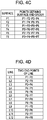
- Figs. 4A, 4B , 4C, and 4D are diagrams showing a method for defining a three-dimensional model according to the first embodiment.
- the three-dimensional model is defined by a set of points, information concerning surfaces defined by connecting the points, and information concerning line segments bounding the surfaces.
- the three-dimensional model in the first embodiment has a rectangular parallelepiped shape with eight points P1 to P8, and the coordinate system of the rectangular parallelepiped model is defined with an X-axis extending in the direction from the point P1 to the point P4, a Y-axis extending in the direction from the point P5 to the point P1, and a Z-axis extending in the direction from the point P1 to the point P2.
- the origin is set at the point P5.
- the rectangular parallelepiped model is defined by surfaces F1 to F6.
- the rectangular parallelepiped model is also defined by line segments L1 to L12.
- each of the points P1 to P8 is represented by three-dimensional coordinate values.
- each of the surfaces F1 to F6 is represented by IDs of points defining that surface and the order by which the points are connected.
- each of the line segments L1 to L12 is represented by IDs of two end points thereof.
- Figs. 5A and 5B are diagrams showing projection of the three-dimensional model onto the image in step S1040.
- Fig. 5A shows the captured image
- Fig. 5B shows an image in which the three-dimensional model is projected on the captured image.
- a deviation occurs between the actually captured image and the projected image of the three-dimensional model indicated by bold lines.
- broken lines indicate hidden line segments that cannot be observed from the position and the orientation.
- step S1050 image features are detected.
- the image features are detected as follows.
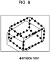
- Fig. 6 is a diagram showing the division points on the image of the three-dimensional model.
- the number N of division points can be controlled by changing the intervals between the division points on the image.
- the intervals between the division points on the image may be changed in every frame so that the number of division points can be constant.
- step S1050 The image-feature detection process performed in step S1050 will now be described with reference to a flowchart shown in Fig. 7 .
- step S1110 the variable "i" is set to 1.
- step S1120 it is determined whether or not a given division point DPi is visible. Specifically, if the division point DPi is occluded by another surface of the three-dimensional model, i.e., if the division point DPi lies on the broken lines shown in Fig. 6 , the division point DPi is not visible.
- the determination as to whether or not the division point DPi is visible can be performed by, for example, as disclosed in Document 8, rendering the division point DPi after rendering the three-dimensional model using graphics hardware, and determining whether or not a depth buffer has been updated in the graphics hardware. If the division point DPi is not visible, the process proceeds to step S1150. If the division point DPi is visible, the process proceeds to step S1130.
- step S1130 it is determined whether or not the division point DPi is occluded by the occluding object designated in step S1010. Specifically, if the value of an occluding region flag Fj associated with the image coordinates of the division point DPi is 1, it is determined that the division point DPi is occluded by the occluding object. If the value of the flag Fj is 0, it is determined that the division point DPi is not occluded. If it is determined that the division point DPi is occluded, the process proceeds to step S1150. If it is determined that the division point DPi is not occluded, the process proceeds to step S1140, and an image feature is detected.
- step S1140 an image feature corresponding to the division point DPi is detected.
- image features are edges.
- Figs. 8A and 8B are diagrams showing a method for detecting an image feature according to the first embodiment.
- a line segment hereinafter referred to as a "search line” parallel to the normal to the projected line segment and passing through the division point.
- search line a line segment parallel to the normal to the projected line segment and passing through the division point.
- the image coordinates of a pixel on a search line may have non-integer values.
- an average of occluding region flags is determined by bilinear interpolation using the values of the occluding region flags Fj for four nearby points. If the average is greater than 0.5, it is determined that the corresponding pixel is occluded, and edge detection is not performed. An edge is present on a search line at a position where the intensity gradient has an extreme value (see Fig. 8B ).
- the closest edge to the division point is designated as a corresponding point, and image coordinates of the corresponding point and three-dimensional coordinates of the division point are stored. While in the first embodiment, the closest edge to the division point is designated as a corresponding point, the corresponding point is not limited to that edge, and an edge exhibiting the largest absolute value of an extreme value of the intensity gradient may be designated as a corresponding point.
- a plurality of points rather than one point may be stored as candidate corresponding points within the scope of the present invention.
- step S1150 the variable "i" is incremented by one, and the process proceeds to step S1160. If the process has been completed for all division points DPi, the process ends; otherwise, the process returns to step S1120.
- step S1060 the position and orientation of the image-pickup apparatus 100 are determined.
- the number of division points whose corresponding points have been determined in step S1140 from among the division points DPi is denoted by Nc.
- the position and orientation of the image-pickup apparatus 100 are determined by correcting the rough position and orientation of the image-pickup apparatus 100 through iterative calculations.
- Fig. 9 is a diagram showing a method for calculating the position and orientation of the image-pickup apparatus 100 using line segment information. In Fig. 9 , the x-axis and the y-axis are plotted in the horizontal direction and vertical direction of the image, respectively.
- the coordinates of a given division point is represented by (u, v), and a line segment L to which the given division point belongs on the image is inclined at an inclination ⁇ with respect to the x-axis.
- the normal vector of the line segment L is represented by (sin ⁇ , - cos ⁇ ).
- the coordinates of the corresponding point of the division point is represented by (u', v').
- a point (x, y) on a straight line (indicated by a broken line shown in Fig.
- the image coordinates of the division point are functions of the position and orientation of the image-pickup apparatus 100.
- the position and orientation of the image-pickup apparatus 100 has six degrees of freedom. It is assumed that a parameter indicating the position and orientation of the image-pickup apparatus 100 is denoted by p.
- the parameter p is a six-dimensional vector having three elements representing the position of the image-pickup apparatus 100 and three elements representing the orientation of the image-pickup apparatus 100.
- Each of the three elements representing the orientation is represented by, for example, an Euler angle, or a three-dimensional vector whose direction and magnitude represent the rotation axis and rotation angle, respectively, or the like.
- a correcting value ⁇ p of the position and orientation parameter p of the image-pickup apparatus 100 is calculated so that the point (x, y) represented by Ex. (3) is present on the straight line represented by Eq. (2).
- the correcting value ⁇ p is determined using the generalized inverse matrix (J T ⁇ J) -1 of the matrix J.
- edges may often be erroneously detected, and a robust estimation method described below is used.
- a division point corresponding to an erroneously detected edge has a large error d-r. Therefore, the contribution to the simultaneous equations represented by Eqs. (6) and (7) is large, resulting in low accuracy of the correcting value ⁇ p.
- a division point having a large error d-r is assigned a small weight, and a division point having a small error d-r is assigned a large weight.
- the weighting matrix W is an Nc ⁇ Nc square matrix containing zeros except for the diagonal elements and the weights w i as the diagonal elements.
- the obtained correcting value ⁇ p is used to update the rough position and orientation of the image-pickup apparatus 100. In this way, the position and orientation of the image-pickup apparatus 100 are determined in step S1060.
- step S1070 it is determined whether or not the calculation of the position and orientation of the image-pickup apparatus 100 has converged. If the correcting value determined in step S1060 is sufficiently small, or the total sum of the errors r-d is sufficiently small, or the total sum of the errors r-d does not change, it is determined that the calculation of the position and orientation of the image-pickup apparatus 100 has converged, and the process proceeds to step S1080. If it is determined that the calculation has not converged, the position and orientation of the image-pickup apparatus 100 updated in step S1060 are designated as a new rough position and orientation of the image-pickup apparatus 100. Then, the process returns to step S1060, and the values ⁇ , r, and d are re-calculated to determine the correcting value ⁇ p again.
- step S1080 it is determined whether or not an instruction for finishing the position and orientation calculation process has been received. If the instruction has been received, the process ends, otherwise, the process returns to step S1020.
- a virtual-space image is superimposed on the captured image using the position and orientation of the image-pickup apparatus 100 obtained by the position-and-orientation measurement method described with reference to the flowchart shown in Fig. 3 .
- Figs. 11A and 11B are diagrams showing a computer graphics superimposing (synthesizing) method according to the first embodiment.
- Fig. 11A shows an image generated without taking account of the occlusion relationship between a real object (e.g., a hand) and a virtual object (e.g., a virtual cylinder) in which an image of the virtual object generated on the basis of the position and orientation of the image-pickup apparatus 100 is superimposed on the captured image.
- a real object e.g., a hand
- a virtual object e.g., a virtual cylinder
- the virtual object needs to be rendered behind the hand.
- a region detected as the occluding region in the first embodiment is a hand region, and the image of the virtual object is not rendered in the pixels corresponding to the detected occluding region to generate a natural AR image shown in Fig. 11B .
- an occluding region of an image where an occluding object occludes an observation target object on the image is detected, and no image features are detected in the occluding region. Therefore, the position and orientation of the observer relative to the observation target object can be stably calculated with high accuracy.
- an object occluding an observation target object is a hand but is not limited thereto, and may be any other object having features on a two-dimensional image, such as a face.
- a database of face images is determined in advance, and a captured image is matched with the face images in the database. It is determined that a region of the image matched with the face images is occluded by a face, and no image features are detected in that region. With this method, stable high-accuracy position and orientation calculation can be achieved.
- an occluding region is detected on the basis of the color of a hand. If an occluding object has a unique color, an occluding region may be detected on the basis of the unique color. For example, when a user wears orange-colored gloves on his/her hands, an orange-colored region in a captured image may be detected as an occluding region.
- an occluding region may be detected on the basis of the figure pattern of the occluding object instead of the color. For example, when a user wears dot-patterned gloves on his/her hands, a dot-patterned region in a captured image may be detected as an occluding region.
- a hand region is detected on a captured image and is designated as an occluding region. No image features are detected in the occluding region, thereby achieving stable high-accuracy calculation of the position and orientation of an observer relative to an observation target object.
- an occluding region is not detected using features on a two-dimensional image in the manner described in the first embodiment, but is detected from a captured image using a model of an occluding object and the rough position and orientation of the occluding object and an image-pickup apparatus.
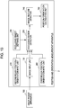
- Fig. 13 shows an example structure of a position-and-orientation-measurement apparatus 2 according to the second embodiment.
- an image-pickup apparatus 100 is connected to the position-and-orientation-measurement apparatus 2.
- the position-and-orientation-measurement apparatus 2 includes an occluding-object-defining unit 210, an image-input unit 120, an occluding-region detector 230, an image-feature detector 140, a position/orientation-calculating unit 150, a first rough-position/orientation-input unit 260, and a second rough-position/orientation-input unit 270. Sections of the position-and-orientation-measurement apparatus 2 having functions similar to those in the position-and-orientation-measurement apparatus 1 shown in Fig. 1 are represented by the same reference numerals.
- Fig. 14 is a diagram showing a typical situation where the position-and-orientation-measurement apparatus 2 according to the second embodiment is applied.
- an observation target object 30 and a second observer 40 exist in a space observed by an observer.
- the second observer 40 may occlude the observation target object 30. It is assumed that both observers are wearing HMDs and enjoying their AR experience. In Fig. 14 , the second observer 40 is wearing a HMD 50.
- the position-and-orientation-measurement apparatus 2 according to the second embodiment is configured to determine the position and orientation of the image-pickup apparatus 100 relative to the observation target object 30.
- the occluding-object-defining unit 210 defines an occluding object model.
- the occluding-object-defining unit 210 defines a rectangular parallelepiped model containing a human-body object on the basis of a coordinate system of the HMD 50, and stores the definition of the model in a storage unit (not shown).
- the operation of the image-input unit 120, the image-feature detector 140, and the position/orientation-calculating unit 150 is similar to that in the first embodiment, and a description thereof is thus omitted.
- the first rough-position/orientation-input unit 260 inputs a rough position and orientation of the image-pickup apparatus 100.
- the second rough-position/orientation-input unit 270 inputs a rough position and orientation of the second observer 40, that is, the HMD 50.
- the occluding-region detector 230 detects an occluding region where the observation target object 30 is occluded in a captured image on the basis of position and orientation information obtained from the first rough-position/orientation-input unit 260 and the second rough-position/orientation-input unit 270, and the occluding object model defined by the occluding-object-defining unit 210.
- the detected occluding region is output to the image-feature detector 140.
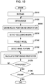
- Fig. 15 is a flowchart showing a process procedure according to the second embodiment.
- step S2010 initialization is performed.
- an occluding object is defined, and the position and orientation of the image-pickup apparatus 100 relative to the observation target object 30 are roughly determined.
- the occluding object in the second embodiment is the second observer 40, and, as shown in Fig. 16 , a rectangular parallelepiped object 60 containing the second observer 40 is designated. Referring to Fig. 16 , the height, horizontal width, and vertical width of the second observer 40 are roughly measured in advance, and the rectangular parallelepiped object 60 containing the second observer 40 is determined. The position and orientation of the rectangular parallelepiped object 60 are also determined on the basis of the coordinate system of the HMD 50. Further, the position and orientation of the image-pickup apparatus 100 are roughly determined in the manner described in the first embodiment. After the initialization is performed, the process proceeds to step S1020.
- step S1020 an image captured by the image-pickup apparatus 100 is loaded into the position-and-orientation-measurement apparatus 2 via the image-input unit 120.
- the image loaded in step S1020 is transmitted to the occluding-region detector 230 and the image-feature detector 140.
- step S2090 the first rough-position/orientation-input unit 260 inputs a rough position and orientation of the image-pickup apparatus 100.
- the second rough-position/orientation-input unit 270 inputs a rough position and orientation of the HMD 50 worn by the second observer 40.
- the rough position and orientation of the image-pickup apparatus 100 are, for example, the position and orientation calculated in the preceding frame.
- the rough position and orientation of the HMD 50 are the up-to-date position and orientation calculated using the position-and-orientation-measurement apparatus 2 that is operated by the observer 40.
- Two position-and-orientation-measurement apparatuses may run on the same computer, and may exchange calculated position and orientation results via interprocess communication.
- the two position-and-orientation-measurement apparatuses may run on different computers, and may exchange calculated position and orientation results via a network.
- the HMD 50 may be provided with a magnetic, optical, or ultrasonic position-and-orientation measurement sensor with six degrees of freedom, and a rough position and orientation may be obtained from the output values of the sensor.
- the HMD 50 may be provided with a three-degree-of-freedom orientation sensor and position sensor, and a position and orientation may be obtained from a projected image of a marker on an image captured by an internal image-pickup apparatus of the HMD 50 and measurement values of the three-degree-of-freedom sensors. That is, any method capable of providing rough position and orientation determination may be used. A rough position and orientation of the image-pickup apparatus 100 may be obtained in a manner similar to that for the HMD 50.
- step S2030 an occluding region is detected.
- the rectangular parallelepiped object 60 is rendered on an image captured by the image-pickup apparatus 100 on the basis of the rough positions and orientations of the image-pickup apparatus 100 and the HMD 50 obtained in step S2090.
- a portion where the rectangular parallelepiped object 60 is rendered on the image having the rectangular parallelepiped object 60 rendered thereon is output to the image-feature detector 140 as an occluding region.
- Fig. 17B is a mask image represented in white and black, which is generated using the flags Fi. Image features are detected only in the white portion of the mask image.
- steps S1040, S1050, S1060, S1070, and S1080 is similar to that in the first embodiment, and a description thereof is thus omitted.
- an occluding region of a captured image is detected using a model of an occluding object and rough positions and orientations of the occluding object and an image-pickup apparatus. No image features are detected in the occluding region. Therefore, stable high-accuracy calculation of the position and orientation of an observer relative to an observation target object can be achieved.
- no image features are detected in a region detected as an occluding region.
- a boundary between a hand region and a non-hand region does not necessarily have the same color as the hand. Therefore, image features may be erroneously detected at the boundary between the hand region and the non-hand region.
- the detected occluding region and the boundary thereof may be included in an occluding region.
- the occluding region is extended outward by one pixel so that the boundary thereof can be included in the occluding region.
- a region neighboring the occluding region as shown in Fig. 18B , may be included in the occluding region.
- the occluding region is extended by several pixels instead of one pixel.
- the size of the rectangular parallelepiped object 60 may be increased to achieve a similar advantage.
- an occluding region is detected before the detection of image features, and image features are detected in a region other than the occluding region.
- the image-feature detector may be configured to detect image features without taking an occluding region into account
- the position/orientation-calculating unit may be configured to determine whether or not the detected image features are included in an occluding region and to calculate the position and orientation of the image-pickup apparatus only using the image features that are not included in the occluding region.
- the detection of image features and the detection of an occluding region may be performed in parallel on a computer.
- edges are used as image features.
- the image features are not limited to edges, and may be point features.
- the point features are generally called feature points, interest points, or the like, and points such as points exhibiting an extreme intensity value on an image or corner points (vertices) are mainly detected.
- Point features can be detected using the Harris corner detector, which is disclosed in, for example, C. Harris and M. Stephens, "A Combined Corner and Edge Detector", Proc. 4th Alvey Vision Conf., PP. 147-151, 1998 (hereinafter referred to as "Document 10").
- Harris corner detector which is disclosed in, for example, C. Harris and M. Stephens, "A Combined Corner and Edge Detector", Proc. 4th Alvey Vision Conf., PP. 147-151, 1998 (hereinafter referred to as "Document 10").
- Harris corner detector which is disclosed in, for example, C. Harris and M. Stephens, "A Combined Corner and Edge Detector", Proc. 4th Al
- Point features are detected in a region other than an occluding region detected in the first and second embodiments to prevent erroneous detection in a manner similar to that in edge detection. Therefore, stable high-accuracy calculation of the position and orientation of the image-pickup apparatus can be achieved.
- the position and orientation of an observer relative to an observation target object are determined, the position and orientation of the observation target object relative to the observer may be determined.
- either the position or orientation of the observer or observation target object may be determined using any other method capable of providing determination of either the position or orientation of the observer or observation target object.
- the orientation of the observer or observation target object can be measured by a gyro sensor attached to the observation target object or the body of the observer.
- the functions of the embodiments described above are also achieved by providing a computer (or a central processing unit (CPU) or a micro-processing unit (MPU)) of an apparatus or system connected to various devices with program code of software implementing the functions of the embodiments described above so as to operate the various devices to achieve the functions of the embodiments described above, and causing the computer of the system or apparatus to operate the various devices according to the program code.
- a computer or a central processing unit (CPU) or a micro-processing unit (MPU) of an apparatus or system connected to various devices with program code of software implementing the functions of the embodiments described above so as to operate the various devices to achieve the functions of the embodiments described above, and causing the computer of the system or apparatus to operate the various devices according to the program code.
- Examples of the storage medium storing the program code may include a floppy disk, a hard disk, an optical disk, a magneto-optical disk, a compact disk read-only memory (CD-ROM), a magnetic tape, a non-volatile memory card, and a ROM.
- the functions of the embodiments described above may be achieved through the use of the program code in combination with an operating system (OS), other software applications, or the like running on the computer. This also falls within the scope of the present invention.
- OS operating system
- the provided program code may be stored in a memory of a function extension board placed in the computer or a function extension unit connected to the computer, and thereafter a CPU or the like of the function extension board or the function extension unit may execute part of or the entirety of actual processing according to the instruction of the program code to achieve the functions of the embodiments described above. This also falls within the scope of the present invention.
Description
- The present invention relates to a technique for calculating at least one of the position and orientation of an image-pickup apparatus or an observation target object on the basis of image features detected on a captured image.
- Recently, research of Mixed Reality (MR) techniques for providing a seamless integration of real and virtual spaces has been actively conducted. Among these MR techniques, especially an Augmented Reality (AR) technique that superimposes a virtual space on a real space has received attention.
- An image-providing apparatus employing the AR technique is mainly implemented by a video see-through or optical see-through head-mounted display (HMD).
- In a video see-through HMD, a virtual-space image (e.g., virtual objects or text information rendered by computer graphics) generated according to the position and orientation of an image-pickup apparatus such as a video camera in the HMD is superimposed on a real-space image captured by the image-pickup apparatus, and the resulting synthesized image is displayed to a user. In an optical see-through HMD, a virtual-space image generated according to the position and orientation of the HMD is displayed on a transmissive-type display to allow a synthesized image of real and virtual spaces to be formed on the retina of a user.
- One of the most serious problems with the AR technique is accurate registration between real and virtual spaces, and many attempts have been made to address this problem. In a video see-through HMD, the problem of registration in AR involves accurate determination of the position and orientation of the image-pickup apparatus in a scene (that is, in a reference coordinate system defined in the scene). In an optical see-through HMD, the problem of registration involves accurate determination of the position and orientation of the HMD in a scene.
- To solve the former problem, it is common to place artificial markers in a scene and determine the position and orientation of the image-pickup apparatus in the reference coordinate system using the markers. The position and orientation of the image-pickup apparatus in the reference coordinate system are determined from the correspondences between detected positions of the markers in an image captured by the image-pickup apparatus and known information, namely, three-dimensional positions of the markers in the reference coordinate system.
- To solve the latter problem, it is common to attach an image-pickup apparatus to the HMD and determine the position and orientation of the image-pickup apparatus in a manner similar to that described above to determine the position and orientation of the HMD on the basis of the determined position and orientation of the image-pickup apparatus.
- Methods for determining the position and orientation of an image-pickup apparatus on the basis of correspondences between image coordinates and three-dimensional coordinates have been proposed for a long time in the fields of photogrammetry and computer vision.
- A method for determining the position and orientation of an image-pickup apparatus by solving nonlinear simultaneous equations on the basis of correspondence of three points is disclosed in R. M. Haralick, C. Lee, K. Ottenberg, and M. Nolle, "Review and Analysis of Solutions of the Three Point Perspective Pose Estimation Problem", International Journal of Computer Vision, vol. 13, No. 3, PP. 331-356, 1994 (hereinafter referred to as "
Document 1"). - A method for determining the position and orientation of an image-pickup apparatus by optimizing a rough position and orientation of the image-pickup apparatus through iterative calculations on the basis of correspondences between image coordinates and three-dimensional coordinates of a plurality of points is disclosed in D. G. Lowe, "Fitting Parameterized Three-Dimensional Models to Images", IEEE Transactions Pattern Analysis and Machine Intelligence, vol. 13, No. 5, PP. 441-450, 1991 (hereinafter referred to as "
Document 2"). - Another serious problem in AR technology, other than registration, is an occlusion problem in which determination of the in-front/behind relationship between real and virtual spaces is required. For example, when a virtual object is located at a position hidden or occluded by a real object such as a hand, it is necessary to render the real object in front of the virtual object. If the occlusion effect is not taken into account, the virtual object is always rendered in front of the real object, and an observer viewing the resulting image feels unnatural. In Japanese Patent Laid-Open No.
2003-296759 - In N. Yokoya, H. Takemura, T. Okuma, and M. Kanbara, "Stereo vision based video see-through mixed reality," in (Y. Ohta & H. Tamura, eds.) Mixed Reality-Merging Real and Virtual Worlds, Chapter 7, Ohmsha-Springer Verlag, 1999 (hereinafter referred to as "Document 11"), the occlusion problem is overcome by obtaining real-space depth information through stereo matching using images captured by two built-in cameras of an HMD.
- With the recent high-speed performance of computing machines, research of registration using features present in a scene (hereinafter referred to as "natural features"), rather than artificial markers, has been actively carried out.
- Methods for determining the position and orientation of an image-pickup apparatus on the basis of correspondences between image edges and a three-dimensional model of an observation target are disclosed in T. Drummond and R. Cipolla, "Real-time visual tracking of complex structures", IEEE Transaction Pattern Analysis and Machine Intelligence, vol. 24, No. 7, PP. 932-946, 2002 (hereinafter referred to as "Document 3"), and A. I. Comport, E. Marchand, and F. Chaumette, "A real-time tracker for markerless augmented reality", Proceedings of the Second IEEE and ACM International Symposium on Mixed and Augmented Reality (ISMAR03), PP. 36-45, 2003 (hereinafter referred to as "Document 4").
- In these methods, first, (1) a three-dimensional model is projected onto a captured image using a rough position and rough orientation of an image-pickup apparatus. The rough position and rough orientation of the image-pickup apparatus are, for example, the position and orientation calculated in the preceding frame. Then, (2) line segments comprising the projected model are divided into equal intervals on the image, and, for each of the division points, a point (edge) where the intensity gradient is a local maximum in the direction perpendicular to the projected line segment is searched for as a corresponding point. Further, (3) correcting values of the position and orientation of the image-pickup apparatus are determined so that the distances between the corresponding points found for the individual division points and the corresponding projected line segments become minimum on the image, and the position and orientation of the image-pickup apparatus are updated. The three-dimensional model is again projected onto the captured image using the updated position and orientation of the image-pickup apparatus, and the step (3) is iterated until the sum of the distances has converged to the optimum. Thus, the final position and orientation of the image-pickup apparatus are obtained.
- In the above step (2), erroneous detection may occur if the accuracy of the rough position and rough orientation of the image-pickup apparatus is low. That is, wrong points may be detected as corresponding points. If such erroneous detection occurs, the iterative calculations may not be converged in the step (3), or the accuracy of the obtained position and orientation of the image-pickup apparatus may be low, resulting in low-accuracy AR registration.
- In Documents 3 and 4, therefore, an M-estimator, which is a robust estimation method, is used to minimize the sum of weighted errors by assigning a small weight to data having a large distance between the corresponding point and the line segment and assigning a large weight to data having a small distance. Therefore, any influence of erroneous detection is eliminated.
- In L. Vacchetti, V. Lepetit, and P. Fua, "Combining edge and texture information for real-time accurate 3D camera tracking", Proceedings of the Third IEEE and ACM International Symposium on Mixed and Augmented Reality (ISMAR04), PP. 48-57, 2004 (hereinafter referred to as "Document 5"), a plurality of candidate points are extracted and stored in the search step (2), and the closest points to the projected line segments are selected from among the plurality of candidate points each time the step (3) is repeated. Therefore, any influence of erroneous detection is eliminated.
- In H. Wuest, F. Vial, and D. Stricker, "Adaptive Line Tracking with Multiple Hypotheses for Augmented Reality", Proceedings of the Fourth IEEE and ACM International Symposium Mixed and Augmented Reality (ISMAR05), PP. 62-69, 2005 (hereinafter referred to as "Document 6"), information concerning visual properties of edges near line segments on an image is held to eliminate the influence of erroneous detection caused by changes in lighting or changes in point of view.
- Methods for determining the position and orientation of an image-pickup apparatus using point features, rather than edges, on an image are disclosed in G. Simon, A. W. Fitzgibbon, and A. Zisserman, "Markerless Tracking using Planar Structures in the Scene", Proc. Int'l Symp. on Augmented Reality 2000 (ISAR2000), PP. 120-128, 2000 (hereinafter referred to as "Document 7"), and I. Skrypnyk and D. G. Lowe, "Scene Modelling, Recognition and Tracking with Invariant Image features", Proc. The Third Int'l Symp. on Mixed and Augmented Reality (ISMAR04), PP. 110-119, 2004 (hereinafter referred to as "Document 8").
- Point features are features represented in terms of position (image coordinates) on an image and image information around. For example, point features are detected using the Harris operator, Moravec operator, or the like.
- In Document 7, point features on the same plane in a three-dimensional space are tracked in successive frames, and the position and orientation of an image-pickup apparatus are calculated on the basis of the relationship between the positions of these points on the plane and the image coordinates of the corresponding point features.
- In Document 8, the position and orientation of an image-pickup apparatus are determined using point features having feature information invariant to scale change and rotation change on an image on the basis of correspondences between image coordinates and three-dimensional coordinates of the point features. In Document 8, point features are not tracked in successive frames. On the contrary, matching is performed between a predetermined point feature database and point features detected in the current frame to identify the point features in every frame.
- The point-feature-based methods also have a problem of erroneous detection, like the edge-based methods. In Documents 7 and 8, point features detected as outliers are removed using the Random Sample Consensus (RANSAC) algorithm. In the RANSAC-based outlier removal scheme, corresponding points are selected at random, and the position and orientation of the image-pickup apparatus are calculated. When the number of corresponding points meeting the calculated values is the maximum, corresponding points that are not included in the set of the corresponding points are removed as outliers.
- There is a method of the related art using artificial markers, in which erroneous detection of the markers is prevented using chroma-keying. ProSet and SmartSet systems, which are virtual studio systems of Orad Hi-Tec systems Ltd., utilize traditional blue or green screen chroma-key techniques to separate a human figure from a background.
- On the background, an artificial pattern for registration having a color similar to that of the background is placed, and the position and orientation of a camera are estimated using the detected pattern on the captured image. Since the registration pattern is separated as the background from the human figure using chroma-keying, the registration pattern may not be erroneously detected on the human image. Therefore, stable estimation of the position and orientation of the camera can be achieved. Furthermore, since the registration pattern is removed as the background using chroma-keying, the registration pattern is not observed on a composite image in which a computer graphics (CG) image is rendered on the background.
- The above-described technique to avoid erroneous detection of the markers, proposed by Orad Hi-Tec systems Ltd., is a technique for use in virtual studio applications. In a virtual studio, a human figure is extracted from the background, and a CG image is rendered onto a background portion so as to be combined with an image of the human figure. Therefore, a blue screen can be used as a background, and the background can be extracted using chroma-keying.
- In AR systems, however, a CG image is superimposed on a real background image. Therefore, it is difficult to extract the background by performing simple processing such as chroma-keying, and it is also difficult to adopt the technique proposed by Orad Hi-Tec systems Ltd. to avoid erroneous detection of natural features on the background image.
- In the related art, the process for detecting natural features for registration and the process for determining the in-front/behind relationship between a virtual object and a real occluding object such as a hand are separately performed. In an image region where the occluding object is in front of the virtual object, the natural features used for registration must not be detected. Therefore, it can be expected that erroneous detection may be prevented by using information concerning the in-front/behind relationship for image-feature detection. In the related art, however, information concerning the in-front/behind relationship is not used for natural feature detection.
- A measurement device arranged to measure the position and orientation of an occluding object allows the in-front/behind relationship between an observation target object and the occluding object to be determined using measurement results of the measurement device. In the related art, however, information concerning the measured position and orientation of the occluding object is not used for natural feature detection.
- The present invention provides a technique in which erroneous detection of image features can be prevented when an observation target object is occluded by an occluding object and registration stability can be improved.
- The present invention further provides a technique using a measurement device arranged to measure the position and orientation of an occluding object, in which erroneous detection of image features can be prevented using information obtained from the measurement device when an observation target object is occluded by the occluding object and registration stability can be improved. occluding object and registration stability can be improved.
- The present invention in its first aspect provides an image-processing apparatus as specified in
claims 1 to 11. - The present invention in its second aspect provides an image-processing method as specified in claim 12.
- The present invention in its third aspect provides a computer program as specified in claim 13.
- Further features of the present invention will become apparent from the following description of exemplary embodiments with reference to the attached drawings.
-
-
Fig. 1 is a diagram showing an example structure of a position-and-orientation-measurement apparatus according to a first embodiment of the present invention. -
Fig. 2 is a diagram showing an example typical situation where the position-and-orientation-measurement apparatus according to the first embodiment is applied. -
Fig. 3 is a flowchart showing the processing operation of the position-and-orientation-measurement -
Figs. 4A, 4B ,4C, and 4D are diagrams showing a method for defining a three-dimensional model according to the first embodiment. -
Figs. 5A and 5B are diagrams showing projection of the three-dimensional model onto an image. -
Fig. 6 is a diagram showing division points plotted on an image of the three-dimensional model. -
Fig. 7 is a flowchart showing a procedure of an image-feature detection process according to the first embodiment. -
Figs. 8A and 8B are diagrams showing a method for detecting an image feature according to the first embodiment. -
Fig. 9 is a diagram showing a method for calculating the position and orientation of an image-pickup apparatus using line segment information. -
Figs. 10A and 10B are diagrams showing detection of an occluding region according to the first embodiment. -
Figs. 11A and 11B are diagrams showing a computer-graphics superimposing (synthesizing) method according to the first embodiment. -
Fig. 12 is a diagram showing detection of an occluding region according to a modification example of the first embodiment. -
Fig. 13 is a diagram showing an example structure of a position-and-orientation-measurement apparatus according to a second embodiment of the present invention. -
Fig. 14 is a diagram showing an example typical situation where the position-and-orientation-measurement apparatus according to the second embodiment is applied. -
Fig. 15 is a flowchart showing a process procedure according to the second embodiment. -
Fig. 16 is a diagram showing a definition method of a model of an occluding object according to the second embodiment. -
Figs. 17A and 17B are diagrams showing detection of an occluding region according to the second embodiment. -
Figs. 18A and 18B are diagrams showing a region neighboring the occluding region. - Embodiments of the present invention will be described in detail with reference to the drawings.
- A first embodiment of the present invention will be described with respect to a registration method using edges detected on an image. More specifically, a position-and-orientation-measurement apparatus and a position-and-orientation-measurement method for determining the position and orientation of an observer relative to an observation target object observed by the observer when the observation target is occluded by a hand of the observer will be described.
-
Fig. 1 shows an example structure of a position-and-orientation-measurement apparatus 1 according to the first embodiment. As shown inFig. 1 , the position-and-orientation-measurement apparatus 1 includes an occluding-object-definingunit 110, an image-input unit 120, an occluding-region detector 130, an image-feature detector 140, and a position/orientation-calculatingunit 150. An image-pickup apparatus 100 is connected to the image-input unit 120. -
Fig. 2 is a diagram showing a typical situation where the position-and-orientation-measurement apparatus 1 according to the first embodiment is applied. An observer wears the image-pickup apparatus 100, and anobservation target object 10, which is a real object, is partially occluded byhands 20 of the observer. The position-and-orientation-measurement apparatus 1 according to the first embodiment is configured to determine the position and orientation of the image-pickup apparatus 100 relative to theobservation target object 10. - In the first embodiment, an observation target object is located behind an occluding object, i.e., an observer's hand.
- The occluding-object-defining
unit 110 defines an occluding object in advance before position and orientation measurement, and stores the definition of the occluding object in a storage unit (not shown). In the first embodiment, the occluding-object-definingunit 110 defines the color of a hand. On an image, pixels corresponding to a region having the same color as the hand can represent an object occluded by the hand. In the definition of the color of the hand, for example, a representative value of the color of the hand may be represented by three components of red (R), green (G), and blue (B), and a range of values available for each of the components may be designated. An elliptic region in an RGB space using the RGB components as three orthogonal axes may also be defined. Alternatively, an elliptic region in a UV plane using U and V components as two orthogonal axes, wherein the U and V components are color components in a YUV color space, may be defined instead of the RGB components. The method for defining the color of a hand is not limited to those described above, and any other definition method for representing a color or a color region may be used. - The image-
input unit 120 receives an image captured by the image-pickup apparatus 100. The image-input unit 120 is implemented by a video capture board if the output of the image-pickup apparatus 100 is compatible with analog output formats such as NTSC (National Television System Committee). If the output of the image-pickup apparatus 100 is compatible with digital output formats such as IEEE (Institute of Electrical and Electronic Engineers) 1394, the image-input unit 120 is implemented by, for example, an IEEE 1394 interface board. - The occluding-
region detector 130 detects an occluding region of the captured image input from the image-input unit 120 where the observation target object is occluded by the occluding object defined by the occluding-object-definingunit 110. The detected occluding region is output to the image-feature detector 140. - The image-
feature detector 140 detects an image feature on the image input from the image-input unit 120. Image features are detected only in a region other than the occluding region detected by the occluding-region detector 130. The detected image features are output to the position/orientation-calculatingunit 150. - The position/orientation-calculating
unit 150 calculates the position and orientation of the image-pickup apparatus 100 relative to theobservation target object 10 on the basis of information concerning the image features detected by the image-feature detector 140. - The processing operation of the position-and-orientation-
measurement apparatus 1 according to the first embodiment will now be described. -
Fig. 3 is a flowchart showing the processing operation of the position-and-orientation-measurement apparatus 1 according to the first embodiment. - First, in step S1010, initialization is performed. In the initialization processing of step S1010, an occluding object is defined, and the position and orientation of the image-
pickup apparatus 100 relative to the observation target object are roughly determined. The occluding object in the first embodiment is an observer's hand, and a color region representing the color of the hand is designated. In the designation process of the color region, for example, an image including the hand as the occluding object is captured in advance, and a hand region is specified in the image using a mouse. The color of the hand region is mapped onto a UV plane, and an elliptic area including the mapped hand region on the UV plane is designated as a color region representing the color of the hand. - A position-and-orientation-measurement method described below according to the first embodiment is a method of updating the rough position and orientation of the image-
pickup apparatus 100 using information concerning image features. Therefore, the position and orientation of the image-pickup apparatus 100 need to be roughly determined in advance prior to the position and orientation measurement. For example, a predetermined position and orientation may be designated, and the image-pickup apparatus 100 may be moved to the designated position and orientation. - Alternatively, as disclosed in H. Kato and M. Billinghurst, "Marker Tracking and HMD Calibration for a Video-Based Augmented Reality Conferencing System", Proc. The 2nd IEEE International Workshop on Augmented Reality (IWAR '99), pp. 85-94, 1999, an artificial marker that is identifiable once it is detected in an image may be used. In this case, three-dimensional positions of vertices of the marker are measured, and the position and orientation of the image-
pickup apparatus 100 are determined from correspondences between image coordinates and three-dimensional positions of the vertices of the artificial marker. The determined position and orientation may be designated as a rough position and orientation of the image-pickup apparatus 100. - Alternatively, a magnetic, optical, or ultrasonic position and orientation sensor with six degrees of freedom may be attached to the image-
pickup apparatus 100, and the position and orientation of the image-pickup apparatus 100 obtained from the sensor may be designated as a rough position and orientation of the image-pickup apparatus 100. The position and orientation of the image-pickup apparatus 100 may be measured using a combination of an artificial marker and the above-described position and orientation sensor with six degrees of freedom or an orientation sensor with three degrees of freedom and a position sensor with three degrees of freedom, and the determined position and orientation may be designated as a rough position and orientation of the image-pickup apparatus 100. After the initialization is performed, the process proceeds to step S1020. - In step S1020, an image captured by the image-
pickup apparatus 100 is loaded into the position-and-orientation-measurement apparatus 1 via the image-input unit 120. The image loaded in step S1020 is transmitted to the occluding-region detector 130 and the image-feature detector 140. - Then, in step S1030, an occluding region is detected. Pixels corresponding to the color region representing the color of the hand designated in step S1010 are detected from the image, and are labeled to generate connected regions. Each of the connected regions is dilated to remove noise. The remaining connected regions are output to the image-
feature detector 140 as occluding regions. -
Figs. 10A and 10B are diagrams showing detection of an occluding region according to the first embodiment.Fig. 10A shows an image captured by the image-pickup apparatus 100, in which an observation target object is occluded by a hand. Which pixel in the captured image is occluded by the hand is determined using flags Fi (i = 1, 2, ..., n) each associated with one of the pixels and indicating whether or not the corresponding pixel is occluded, where n denotes the number of pixels in the captured image. Initially, all the flags Fi are set to value "0". Then, the flags Fi associated with the pixels corresponding to the occluding region are set to value "1". The flags Fi are output to the image-feature detector 140 as data indicating the occluding region. -
Fig. 10B shows a mask image represented in white and black, which is generated using the flags Fi. Image features are detected only in the white portion of the mask image. - Then, in step S1040, model projection is performed. Specifically, a three-dimensional model of the observation target object is projected onto the image on the basis of the rough position and orientation of the image-
pickup apparatus 100. The model projection is performed using known camera internal parameters such as focal length and principal point. In the first embodiment, the camera internal parameters are measured in advance and are thus known. -
Figs. 4A, 4B ,4C, and 4D are diagrams showing a method for defining a three-dimensional model according to the first embodiment. The three-dimensional model is defined by a set of points, information concerning surfaces defined by connecting the points, and information concerning line segments bounding the surfaces. - As shown in the left portion of
Fig. 4A , the three-dimensional model in the first embodiment has a rectangular parallelepiped shape with eight points P1 to P8, and the coordinate system of the rectangular parallelepiped model is defined with an X-axis extending in the direction from the point P1 to the point P4, a Y-axis extending in the direction from the point P5 to the point P1, and a Z-axis extending in the direction from the point P1 to the point P2. The origin is set at the point P5. As shown in the middle and right portions ofFig. 4A , the rectangular parallelepiped model is defined by surfaces F1 to F6. - The rectangular parallelepiped model is also defined by line segments L1 to L12. As shown in
Fig. 4B , each of the points P1 to P8 is represented by three-dimensional coordinate values. As shown inFig. 4C , each of the surfaces F1 to F6 is represented by IDs of points defining that surface and the order by which the points are connected. As shown inFig. 4D , each of the line segments L1 to L12 is represented by IDs of two end points thereof. -
Figs. 5A and 5B are diagrams showing projection of the three-dimensional model onto the image in step S1040.Fig. 5A shows the captured image, andFig. 5B shows an image in which the three-dimensional model is projected on the captured image. - When a motion occurs between the image-
pickup apparatus 100 and theobservation target object 10 in successive frames, as shown inFig. 5B , a deviation occurs between the actually captured image and the projected image of the three-dimensional model indicated by bold lines. InFig. 5B , broken lines indicate hidden line segments that cannot be observed from the position and the orientation. - Then, in step S1050, image features are detected. The image features are detected as follows.
- First, division points are set so that the line segments defining the projected three-dimensional model can be divided into equal intervals on the image.
Fig. 6 is a diagram showing the division points on the image of the three-dimensional model. The total number of division points is N, and each of the division points is denoted by DPi (i = 1, 2, ..., N). The number N of division points can be controlled by changing the intervals between the division points on the image. The intervals between the division points on the image may be changed in every frame so that the number of division points can be constant. - The image-feature detection process performed in step S1050 will now be described with reference to a flowchart shown in
Fig. 7 . - First, in step S1110, the variable "i" is set to 1. Then, in step S1120, it is determined whether or not a given division point DPi is visible. Specifically, if the division point DPi is occluded by another surface of the three-dimensional model, i.e., if the division point DPi lies on the broken lines shown in
Fig. 6 , the division point DPi is not visible. The determination as to whether or not the division point DPi is visible can be performed by, for example, as disclosed in Document 8, rendering the division point DPi after rendering the three-dimensional model using graphics hardware, and determining whether or not a depth buffer has been updated in the graphics hardware. If the division point DPi is not visible, the process proceeds to step S1150. If the division point DPi is visible, the process proceeds to step S1130. - In step S1130, it is determined whether or not the division point DPi is occluded by the occluding object designated in step S1010. Specifically, if the value of an occluding region flag Fj associated with the image coordinates of the division point DPi is 1, it is determined that the division point DPi is occluded by the occluding object. If the value of the flag Fj is 0, it is determined that the division point DPi is not occluded. If it is determined that the division point DPi is occluded, the process proceeds to step S1150. If it is determined that the division point DPi is not occluded, the process proceeds to step S1140, and an image feature is detected.
- In step S1140, an image feature corresponding to the division point DPi is detected. In the first embodiment, image features are edges.
Figs. 8A and 8B are diagrams showing a method for detecting an image feature according to the first embodiment. As shown inFig. 8A , for each of the division points, an edge is one-dimensionally searched for along a line segment (hereinafter referred to as a "search line") parallel to the normal to the projected line segment and passing through the division point. It is to be noted that if the value of an occluding region flag Fj associated with the image coordinates of a pixel on a search line is 1, edge detection is not performed on the pixel on the search line. Further, there is a possibility of the image coordinates of a pixel on a search line may have non-integer values. In this case, for example, an average of occluding region flags is determined by bilinear interpolation using the values of the occluding region flags Fj for four nearby points. If the average is greater than 0.5, it is determined that the corresponding pixel is occluded, and edge detection is not performed. An edge is present on a search line at a position where the intensity gradient has an extreme value (seeFig. 8B ). In the first embodiment, if a plurality of edges are present on a search line, the closest edge to the division point is designated as a corresponding point, and image coordinates of the corresponding point and three-dimensional coordinates of the division point are stored. While in the first embodiment, the closest edge to the division point is designated as a corresponding point, the corresponding point is not limited to that edge, and an edge exhibiting the largest absolute value of an extreme value of the intensity gradient may be designated as a corresponding point. Alternatively, as disclosed in Document 7, a plurality of points rather than one point may be stored as candidate corresponding points within the scope of the present invention. - In step S1150, the variable "i" is incremented by one, and the process proceeds to step S1160. If the process has been completed for all division points DPi, the process ends; otherwise, the process returns to step S1120.
- If the process has been completed for all division points DPi, in step S1060 shown in
Fig. 3 , the position and orientation of the image-pickup apparatus 100 are determined. The number of division points whose corresponding points have been determined in step S1140 from among the division points DPi is denoted by Nc. The position and orientation of the image-pickup apparatus 100 are determined by correcting the rough position and orientation of the image-pickup apparatus 100 through iterative calculations.Fig. 9 is a diagram showing a method for calculating the position and orientation of the image-pickup apparatus 100 using line segment information. InFig. 9 , the x-axis and the y-axis are plotted in the horizontal direction and vertical direction of the image, respectively. The coordinates of a given division point is represented by (u, v), and a line segment L to which the given division point belongs on the image is inclined at an inclination θ with respect to the x-axis. The normal vector of the line segment L is represented by (sinθ, - cosθ). The coordinates of the corresponding point of the division point is represented by (u', v'). A point (x, y) on the line segment L satisfies Eq. (1):
Fig. 9 ) parallel to the line L and passing through the corresponding point satisfies Eq. (2):
pickup apparatus 100. The position and orientation of the image-pickup apparatus 100 has six degrees of freedom. It is assumed that a parameter indicating the position and orientation of the image-pickup apparatus 100 is denoted by p. The parameter p is a six-dimensional vector having three elements representing the position of the image-pickup apparatus 100 and three elements representing the orientation of the image-pickup apparatus 100. Each of the three elements representing the orientation is represented by, for example, an Euler angle, or a three-dimensional vector whose direction and magnitude represent the rotation axis and rotation angle, respectively, or the like. By approximating (x, y), as the image coordinates of the division point, using the one-dimensional Taylor expansion in the vicinity of (u, v), the following expression is obtained:


- A correcting value Δp of the position and orientation parameter p of the image-
pickup apparatus 100 is calculated so that the point (x, y) represented by Ex. (3) is present on the straight line represented by Eq. (2). Substituting Ex. (3) into Eq. (2) produces Eq. (4):
- Rearranging Eq. (4) yields Eq. (5):

- Since Eq. (5) is established for Nc division points, linear simultaneous equations for the correcting value Δp, like Eq. (6), are established:

- Eq. (6) is simplified as Eq. (7):

- From Eq. (7), the correcting value Δp is determined using the generalized inverse matrix (JT · J)-1 of the matrix J.
- However, edges may often be erroneously detected, and a robust estimation method described below is used. In general, a division point corresponding to an erroneously detected edge has a large error d-r. Therefore, the contribution to the simultaneous equations represented by Eqs. (6) and (7) is large, resulting in low accuracy of the correcting value Δp. To address this problem, a division point having a large error d-r is assigned a small weight, and a division point having a small error d-r is assigned a large weight. The weights are calculated using the Tukey function given by, for example, Eq. (8):

- The weighting function is not limited to the Tukey function, and any other function that assigns a small weight to a division point having a large error d-r and a large weight to a division point having a small error d-r, such as the Huber function given by the following equation:

- Let the weight assigned to the division point DPi be denoted by wi. A weighting matrix W is defined by Eq. (9) :

- The weighting matrix W is an Nc × Nc square matrix containing zeros except for the diagonal elements and the weights wi as the diagonal elements. The weighting matrix W is used to modify Eq. (7) into Eq. (10) :

- By solving Eq. (10) using Eq. (11) below, the correcting value Δp is determined:

- The obtained correcting value Δp is used to update the rough position and orientation of the image-
pickup apparatus 100. In this way, the position and orientation of the image-pickup apparatus 100 are determined in step S1060. - Then, in step S1070, it is determined whether or not the calculation of the position and orientation of the image-
pickup apparatus 100 has converged. If the correcting value determined in step S1060 is sufficiently small, or the total sum of the errors r-d is sufficiently small, or the total sum of the errors r-d does not change, it is determined that the calculation of the position and orientation of the image-pickup apparatus 100 has converged, and the process proceeds to step S1080. If it is determined that the calculation has not converged, the position and orientation of the image-pickup apparatus 100 updated in step S1060 are designated as a new rough position and orientation of the image-pickup apparatus 100. Then, the process returns to step S1060, and the values θ, r, and d are re-calculated to determine the correcting value Δp again. - In step S1080, it is determined whether or not an instruction for finishing the position and orientation calculation process has been received. If the instruction has been received, the process ends, otherwise, the process returns to step S1020.
- A virtual-space image is superimposed on the captured image using the position and orientation of the image-
pickup apparatus 100 obtained by the position-and-orientation measurement method described with reference to the flowchart shown inFig. 3 . -
Figs. 11A and 11B are diagrams showing a computer graphics superimposing (synthesizing) method according to the first embodiment.Fig. 11A shows an image generated without taking account of the occlusion relationship between a real object (e.g., a hand) and a virtual object (e.g., a virtual cylinder) in which an image of the virtual object generated on the basis of the position and orientation of the image-pickup apparatus 100 is superimposed on the captured image. If the virtual object is located behind the hand, as shown inFig. 11B , the virtual object needs to be rendered behind the hand. A region detected as the occluding region in the first embodiment is a hand region, and the image of the virtual object is not rendered in the pixels corresponding to the detected occluding region to generate a natural AR image shown inFig. 11B . - Accordingly, in the first embodiment, an occluding region of an image where an occluding object occludes an observation target object on the image is detected, and no image features are detected in the occluding region. Therefore, the position and orientation of the observer relative to the observation target object can be stably calculated with high accuracy.
- In the first embodiment, an object occluding an observation target object is a hand but is not limited thereto, and may be any other object having features on a two-dimensional image, such as a face.
- For example, as shown in
Fig. 12 , a database of face images is determined in advance, and a captured image is matched with the face images in the database. It is determined that a region of the image matched with the face images is occluded by a face, and no image features are detected in that region. With this method, stable high-accuracy position and orientation calculation can be achieved. - In the first embodiment, an occluding region is detected on the basis of the color of a hand. If an occluding object has a unique color, an occluding region may be detected on the basis of the unique color. For example, when a user wears orange-colored gloves on his/her hands, an orange-colored region in a captured image may be detected as an occluding region.
- Alternatively, an occluding region may be detected on the basis of the figure pattern of the occluding object instead of the color. For example, when a user wears dot-patterned gloves on his/her hands, a dot-patterned region in a captured image may be detected as an occluding region.
- In the first embodiment, a hand region is detected on a captured image and is designated as an occluding region. No image features are detected in the occluding region, thereby achieving stable high-accuracy calculation of the position and orientation of an observer relative to an observation target object.
- In a second embodiment of the present invention, an occluding region is not detected using features on a two-dimensional image in the manner described in the first embodiment, but is detected from a captured image using a model of an occluding object and the rough position and orientation of the occluding object and an image-pickup apparatus.
-
Fig. 13 shows an example structure of a position-and-orientation-measurement apparatus 2 according to the second embodiment. As shown inFig. 13 , an image-pickup apparatus 100 is connected to the position-and-orientation-measurement apparatus 2. The position-and-orientation-measurement apparatus 2 includes an occluding-object-definingunit 210, an image-input unit 120, an occluding-region detector 230, an image-feature detector 140, a position/orientation-calculatingunit 150, a first rough-position/orientation-input unit 260, and a second rough-position/orientation-input unit 270. Sections of the position-and-orientation-measurement apparatus 2 having functions similar to those in the position-and-orientation-measurement apparatus 1 shown inFig. 1 are represented by the same reference numerals. -
Fig. 14 is a diagram showing a typical situation where the position-and-orientation-measurement apparatus 2 according to the second embodiment is applied. - In a space observed by an observer, an
observation target object 30 and asecond observer 40 exist. Thesecond observer 40 may occlude theobservation target object 30. It is assumed that both observers are wearing HMDs and enjoying their AR experience. InFig. 14 , thesecond observer 40 is wearing aHMD 50. The position-and-orientation-measurement apparatus 2 according to the second embodiment is configured to determine the position and orientation of the image-pickup apparatus 100 relative to theobservation target object 30. - The occluding-object-defining
unit 210 defines an occluding object model. For example, the occluding-object-definingunit 210 defines a rectangular parallelepiped model containing a human-body object on the basis of a coordinate system of theHMD 50, and stores the definition of the model in a storage unit (not shown). The operation of the image-input unit 120, the image-feature detector 140, and the position/orientation-calculatingunit 150 is similar to that in the first embodiment, and a description thereof is thus omitted. - The first rough-position/orientation-
input unit 260 inputs a rough position and orientation of the image-pickup apparatus 100. The second rough-position/orientation-input unit 270 inputs a rough position and orientation of thesecond observer 40, that is, theHMD 50. The occluding-region detector 230 detects an occluding region where theobservation target object 30 is occluded in a captured image on the basis of position and orientation information obtained from the first rough-position/orientation-input unit 260 and the second rough-position/orientation-input unit 270, and the occluding object model defined by the occluding-object-definingunit 210. The detected occluding region is output to the image-feature detector 140. -
Fig. 15 is a flowchart showing a process procedure according to the second embodiment. - First, in step S2010, initialization is performed. In the initialization processing of step S2010, an occluding object is defined, and the position and orientation of the image-
pickup apparatus 100 relative to theobservation target object 30 are roughly determined. The occluding object in the second embodiment is thesecond observer 40, and, as shown inFig. 16 , arectangular parallelepiped object 60 containing thesecond observer 40 is designated. Referring toFig. 16 , the height, horizontal width, and vertical width of thesecond observer 40 are roughly measured in advance, and therectangular parallelepiped object 60 containing thesecond observer 40 is determined. The position and orientation of therectangular parallelepiped object 60 are also determined on the basis of the coordinate system of theHMD 50. Further, the position and orientation of the image-pickup apparatus 100 are roughly determined in the manner described in the first embodiment. After the initialization is performed, the process proceeds to step S1020. - In step S1020, an image captured by the image-
pickup apparatus 100 is loaded into the position-and-orientation-measurement apparatus 2 via the image-input unit 120. The image loaded in step S1020 is transmitted to the occluding-region detector 230 and the image-feature detector 140. - Then, in step S2090, the first rough-position/orientation-
input unit 260 inputs a rough position and orientation of the image-pickup apparatus 100. The second rough-position/orientation-input unit 270 inputs a rough position and orientation of theHMD 50 worn by thesecond observer 40. The rough position and orientation of the image-pickup apparatus 100 are, for example, the position and orientation calculated in the preceding frame. The rough position and orientation of theHMD 50 are the up-to-date position and orientation calculated using the position-and-orientation-measurement apparatus 2 that is operated by theobserver 40. - Two position-and-orientation-measurement apparatuses may run on the same computer, and may exchange calculated position and orientation results via interprocess communication. The two position-and-orientation-measurement apparatuses may run on different computers, and may exchange calculated position and orientation results via a network. The
HMD 50 may be provided with a magnetic, optical, or ultrasonic position-and-orientation measurement sensor with six degrees of freedom, and a rough position and orientation may be obtained from the output values of the sensor. Alternatively, theHMD 50 may be provided with a three-degree-of-freedom orientation sensor and position sensor, and a position and orientation may be obtained from a projected image of a marker on an image captured by an internal image-pickup apparatus of theHMD 50 and measurement values of the three-degree-of-freedom sensors. That is, any method capable of providing rough position and orientation determination may be used. A rough position and orientation of the image-pickup apparatus 100 may be obtained in a manner similar to that for theHMD 50. - Then, in step S2030, an occluding region is detected. First, as shown in
Fig. 17A , therectangular parallelepiped object 60 is rendered on an image captured by the image-pickup apparatus 100 on the basis of the rough positions and orientations of the image-pickup apparatus 100 and theHMD 50 obtained in step S2090. Then, a portion where therectangular parallelepiped object 60 is rendered on the image having therectangular parallelepiped object 60 rendered thereon is output to the image-feature detector 140 as an occluding region.Fig. 17B is a mask image represented in white and black, which is generated using the flags Fi. Image features are detected only in the white portion of the mask image. - The processing of steps S1040, S1050, S1060, S1070, and S1080 is similar to that in the first embodiment, and a description thereof is thus omitted.
- Accordingly, in the second embodiment, an occluding region of a captured image is detected using a model of an occluding object and rough positions and orientations of the occluding object and an image-pickup apparatus. No image features are detected in the occluding region. Therefore, stable high-accuracy calculation of the position and orientation of an observer relative to an observation target object can be achieved.
- In the first and second embodiments, no image features are detected in a region detected as an occluding region.
- For example, in the case shown in
Fig. 10 , while a region having the same color as the color of a hand is detected as an occluding region, a boundary between a hand region and a non-hand region does not necessarily have the same color as the hand. Therefore, image features may be erroneously detected at the boundary between the hand region and the non-hand region. - To prevent such erroneous detection, the detected occluding region and the boundary thereof may be included in an occluding region. For example, the occluding region is extended outward by one pixel so that the boundary thereof can be included in the occluding region. In addition to the boundary shown in
Fig. 18A , a region neighboring the occluding region, as shown inFig. 18B , may be included in the occluding region. In this case, the occluding region is extended by several pixels instead of one pixel. In the second embodiment, the size of therectangular parallelepiped object 60 may be increased to achieve a similar advantage. - In the above-described embodiments, an occluding region is detected before the detection of image features, and image features are detected in a region other than the occluding region.
- However, the image-feature detector may be configured to detect image features without taking an occluding region into account, and the position/orientation-calculating unit may be configured to determine whether or not the detected image features are included in an occluding region and to calculate the position and orientation of the image-pickup apparatus only using the image features that are not included in the occluding region. In this case, it is only required that the detection of image features and the detection of an occluding region be performed prior to the position and orientation calculation. For example, the detection of image features and the detection of an occluding region may be performed in parallel on a computer.
- In the above-described embodiments, edges are used as image features. However, the image features are not limited to edges, and may be point features. The point features are generally called feature points, interest points, or the like, and points such as points exhibiting an extreme intensity value on an image or corner points (vertices) are mainly detected. Point features can be detected using the Harris corner detector, which is disclosed in, for example, C. Harris and M. Stephens, "A Combined Corner and Edge Detector", Proc. 4th Alvey Vision Conf., PP. 147-151, 1998 (hereinafter referred to as "
Document 10"). In Document 8, point features are detected using a method called Scale Invariant Feature Transform (SIFT). - Point features are detected in a region other than an occluding region detected in the first and second embodiments to prevent erroneous detection in a manner similar to that in edge detection. Therefore, stable high-accuracy calculation of the position and orientation of the image-pickup apparatus can be achieved.
- While in the above-described embodiments, the position and orientation of an observer relative to an observation target object are determined, the position and orientation of the observation target object relative to the observer may be determined. Alternatively, either the position or orientation of the observer or observation target object may be determined using any other method capable of providing determination of either the position or orientation of the observer or observation target object. For example, the orientation of the observer or observation target object can be measured by a gyro sensor attached to the observation target object or the body of the observer.
- The functions of the embodiments described above are also achieved by providing a computer (or a central processing unit (CPU) or a micro-processing unit (MPU)) of an apparatus or system connected to various devices with program code of software implementing the functions of the embodiments described above so as to operate the various devices to achieve the functions of the embodiments described above, and causing the computer of the system or apparatus to operate the various devices according to the program code.
- In this case, the functions of the embodiments described above are achieved by the program code of the software, and both the program code and a storage medium storing the program code constitute embodiments of the present invention.
- Examples of the storage medium storing the program code may include a floppy disk, a hard disk, an optical disk, a magneto-optical disk, a compact disk read-only memory (CD-ROM), a magnetic tape, a non-volatile memory card, and a ROM.
- As well as achieving the functions of the embodiments described above by executing the program code read by the computer, the functions of the embodiments described above may be achieved through the use of the program code in combination with an operating system (OS), other software applications, or the like running on the computer. This also falls within the scope of the present invention.
- Further, the provided program code may be stored in a memory of a function extension board placed in the computer or a function extension unit connected to the computer, and thereafter a CPU or the like of the function extension board or the function extension unit may execute part of or the entirety of actual processing according to the instruction of the program code to achieve the functions of the embodiments described above. This also falls within the scope of the present invention.
- While the present invention has been described with reference to exemplary embodiments, it is to be understood that the invention is not limited to the disclosed exemplary embodiments. The scope of the following claims is to be accorded the broadest interpretation so as to encompass all modifications, equivalent structures and functions.
Claims (14)
- An image-processing apparatus comprising:object-defining means (210) configured to define an occluding object that occludes a target object to be observed;image-obtaining means (120) configured to obtain a captured image captured by an image-pickup apparatus (100);region-detecting means (230) configured to detect a region of the captured image including the occluding object from the obtained captured image;image-feature-detecting means (140) configured to detect image features of the target object from the captured image; andcalculating means (150) configured to calculate a position and/or orientation of the image-pickup apparatus that captured the captured image or a position and/or orientation of the target object in the captured image on the basis of the image features detected by the image-feature-detecting means,wherein the image-processing apparatus is configured not to take into account features from the detected region in determining the position and/or orientation of the image-pickup apparatus that captured the image or a position and/or orientation of the target object in the captured image, characterized by:first rough-position-and-orientation-obtaining means (260) configured to obtain a first position and first orientation of the image-pickup apparatus; andsecond rough-position-and-orientation-obtaining means (270) configured to obtain a second position of the occluding object or a second position and second orientation of the occluding object;wherein the object-defining means (210) is configured to define a three-dimensional shape of the occluding object; andwherein the region-detecting means (230) is configured to detect the region including the occluding object from the captured image on the basis of the first position and first orientation of the image-pickup apparatus (100) obtained by the first rough-position-and-orientation-obtaining means, the second position of the occluding object or the second position and second orientation of the occluding object obtained by the second rough-position-and-orientation-obtaining means, and the three-dimensional shape of the occluding object.
- An image-processing apparatus according to Claim 1, wherein the region-detecting means (130) is configured to detect a region comprising a region where the occluding object occludes the target object, or a region where the occluding object occludes the target object and a region adjacent thereto.
- An image-processing apparatus according to Claim 1 or Claim 2, wherein the image-feature-detecting means (140) is configured to detect the image features on the basis of the detected region by detecting in a region of the captured image other than the detected region.
- An image-processing apparatus according to any preceding claim, wherein the calculating means (150) is configured to calculate, on the basis of the detected region, the position and/or orientation of the image-pickup apparatus that captured the captured image or the position and/or orientation of the target object in the captured image on the basis of the image features detected in a region of the captured image other than the detected region.
- An image-processing apparatus according to any preceding claim, wherein the object-defining means (110) is configured to define the occluding object in terms of image-feature information, and
the region-detecting means (130) is configured to detect the region from the captured image on the basis of the defined image-feature information. - An image-processing apparatus according to Claim 5, wherein the image-feature information defining the occluding object comprises a color or a pattern.
- An image-processing apparatus according to Claim 6, wherein the occluding object comprises human skin, and the color comprises the color of the skin.
- An image-processing apparatus according to Claim 5, wherein the image-feature information defining the occluding object comprises features representing a human face region on an image.
- An image-processing apparatus according to any preceding claim, further comprising:virtual-space-image-generating means configured to generate a virtual-space image on the basis of a calculation result of the calculating means; andimage-synthesizing means configured to synthesize the captured image and the virtual-space image,wherein an image in which the captured image and the virtual-space image are synthesized is presented to a user.
- An image-processing apparatus according to Claim 9, wherein the virtual-space image is not synthesized with the region detected by the region-detecting means.
- An image-processing apparatus according to any preceding claim, wherein the image features comprise line features or point features.
- An image-processing method comprising:a holding step of holding definition information defining an occluding object that can occlude a target object to be observed;an image-obtaining step (S1020) of obtaining a captured image captured by an image-pickup apparatus;a region-detecting step (S1030) of detecting a region including the occluding object from the obtained captured image;an image-feature detecting step (S1050) of detecting image features of the target object from the captured image; anda calculating step (S1060) of calculating a position and/or orientation of the image-pickup apparatus that captured the captured image or a position and/or orientation of the target object in the captured image on the basis of the image features detected in the image feature detecting step,wherein the method does not take into account features from the detected region in determining the position and/or orientation of the image-pickup apparatus that captured the image or a position and/or orientation of the target object in the captured imagecharacterized by:a first rough-position-and-orientation-obtaining step of obtaining a first position and first orientation of the image-pickup apparatus; anda second rough-position-and-orientation-obtaining step of obtaining a second position of the occluding object or a rough position and second orientation of the occluding object;wherein the information defining the occluding object defines a three-dimensional shape of the occluding object; andwherein the region-detecting step comprises detecting the region including the occluding object from the captured image on the basis of the first position and first orientation of the image-pickup apparatus (100) obtained in the first rough-position-and-orientation-obtaining step, the second position of the occluding object or the second position and second orientation of the occluding object obtained in the second rough-position-and-orientation-obtaining step, and the three-dimensional shape of the occluding object.
- A computer program for implementing the image-processing method according to Claim 12 by using a computer.
- A storage medium storing a program according to claim 13.
Applications Claiming Priority (1)
| Application Number | Priority Date | Filing Date | Title |
|---|---|---|---|
| JP2006219846A JP4789745B2 (en) | 2006-08-11 | 2006-08-11 | Image processing apparatus and method |
Publications (3)
| Publication Number | Publication Date |
|---|---|
| EP1887523A2 EP1887523A2 (en) | 2008-02-13 |
| EP1887523A3 EP1887523A3 (en) | 2017-01-18 |
| EP1887523B1 true EP1887523B1 (en) | 2018-05-30 |
Family
ID=38725336
Family Applications (1)
| Application Number | Title | Priority Date | Filing Date |
|---|---|---|---|
| EP07114209.5A Expired - Fee Related EP1887523B1 (en) | 2006-08-11 | 2007-08-10 | Image-processing apparatus and method |
Country Status (4)
| Country | Link |
|---|---|
| US (1) | US8144238B2 (en) |
| EP (1) | EP1887523B1 (en) |
| JP (1) | JP4789745B2 (en) |
| CN (1) | CN101162524B (en) |
Families Citing this family (76)
| Publication number | Priority date | Publication date | Assignee | Title |
|---|---|---|---|---|
| US9138636B2 (en) | 2007-05-16 | 2015-09-22 | Eyecue Vision Technologies Ltd. | System and method for calculating values in tile games |
| US8194156B2 (en) * | 2008-01-07 | 2012-06-05 | Sony Ericsson Mobile Communications Ab | EXIF object coordinates |
| KR100912264B1 (en) * | 2008-02-12 | 2009-08-17 | 광주과학기술원 | Method and system for generating user-responsive augmented image |
| JP5111210B2 (en) | 2008-04-09 | 2013-01-09 | キヤノン株式会社 | Image processing apparatus and image processing method |
| US8401276B1 (en) * | 2008-05-20 | 2013-03-19 | University Of Southern California | 3-D reconstruction and registration |
| CN102144245A (en) | 2008-08-22 | 2011-08-03 | 惠普开发有限公司 | Image analysis method and system |
| JP5253066B2 (en) * | 2008-09-24 | 2013-07-31 | キヤノン株式会社 | Position and orientation measurement apparatus and method |
| JP4996585B2 (en) * | 2008-11-20 | 2012-08-08 | 日本放送協会 | Image calibration evaluation apparatus and image calibration evaluation program |
| JP2010134649A (en) * | 2008-12-03 | 2010-06-17 | Canon Inc | Information processing apparatus, its processing method, and program |
| EP2381415A4 (en) | 2008-12-22 | 2018-01-24 | NEC Corporation | Person-judging device, method, and program |
| JP5290865B2 (en) * | 2009-05-18 | 2013-09-18 | キヤノン株式会社 | Position and orientation estimation method and apparatus |
| JP5567908B2 (en) * | 2009-06-24 | 2014-08-06 | キヤノン株式会社 | Three-dimensional measuring apparatus, measuring method and program |
| JP5393318B2 (en) * | 2009-07-28 | 2014-01-22 | キヤノン株式会社 | Position and orientation measurement method and apparatus |
| CN102713931A (en) | 2009-08-04 | 2012-10-03 | 艾修视力科技有限公司 | System and method for object extraction |
| US9595108B2 (en) | 2009-08-04 | 2017-03-14 | Eyecue Vision Technologies Ltd. | System and method for object extraction |
| DE102009049849B4 (en) | 2009-10-19 | 2020-09-24 | Apple Inc. | Method for determining the pose of a camera, method for recognizing an object in a real environment and method for creating a data model |
| US8817071B2 (en) * | 2009-11-17 | 2014-08-26 | Seiko Epson Corporation | Context constrained novel view interpolation |
| JP5617246B2 (en) * | 2010-01-12 | 2014-11-05 | ソニー株式会社 | Image processing apparatus, object selection method, and program |
| US8792728B2 (en) | 2010-09-27 | 2014-07-29 | Hewlett-Packard Development Company, L.P. | Near-duplicate image detection |
| US9122053B2 (en) | 2010-10-15 | 2015-09-01 | Microsoft Technology Licensing, Llc | Realistic occlusion for a head mounted augmented reality display |
| US8884984B2 (en) * | 2010-10-15 | 2014-11-11 | Microsoft Corporation | Fusing virtual content into real content |
| BR112013011485A2 (en) * | 2010-10-25 | 2019-04-02 | Lockheed Martin Corporation | estimation of position and orientation of an underwater vehicle related to underwater structures |
| CA2814839C (en) * | 2010-10-25 | 2018-12-04 | Christian H. Debrunner | Detecting structural changes to underwater structures |
| US9348141B2 (en) * | 2010-10-27 | 2016-05-24 | Microsoft Technology Licensing, Llc | Low-latency fusing of virtual and real content |
| WO2012095846A1 (en) | 2011-01-16 | 2012-07-19 | Eyecue Vision Technologies Ltd. | System and method for identification of printed matter in an image |
| US10109065B2 (en) | 2011-01-25 | 2018-10-23 | Qualcomm Incorporated | Using occlusions to detect and track three-dimensional objects |
| US8724853B2 (en) * | 2011-07-18 | 2014-05-13 | Google Inc. | Identifying a target object using optical occlusion |
| CN103765880B (en) * | 2011-09-12 | 2016-05-18 | 英特尔公司 | The networking of the image that localization is cut apart catches and Three-dimensional Display |
| JP5713885B2 (en) | 2011-12-26 | 2015-05-07 | キヤノン株式会社 | Image processing apparatus, image processing method, program, and storage medium |
| US9230171B2 (en) | 2012-01-06 | 2016-01-05 | Google Inc. | Object outlining to initiate a visual search |
| US9052804B1 (en) | 2012-01-06 | 2015-06-09 | Google Inc. | Object occlusion to initiate a visual search |
| KR101874895B1 (en) * | 2012-01-12 | 2018-07-06 | 삼성전자 주식회사 | Method for providing augmented reality and terminal supporting the same |
| US9691241B1 (en) * | 2012-03-14 | 2017-06-27 | Google Inc. | Orientation of video based on the orientation of a display |
| CN103472909B (en) * | 2012-04-10 | 2017-04-12 | 微软技术许可有限责任公司 | Realistic occlusion for a head mounted augmented reality display |
| GB2502591B (en) | 2012-05-31 | 2014-04-30 | Sony Comp Entertainment Europe | Apparatus and method for augmenting a video image |
| JP6092530B2 (en) | 2012-06-18 | 2017-03-08 | キヤノン株式会社 | Image processing apparatus and image processing method |
| DE112013003541B4 (en) | 2012-08-15 | 2018-10-25 | International Business Machines Corporation | Method, program and system for feature extraction |
| GB201310373D0 (en) * | 2013-06-11 | 2013-07-24 | Sony Comp Entertainment Europe | Head-Mountable Apparatus and systems |
| CN104238726B (en) * | 2013-06-17 | 2017-07-18 | 腾讯科技(深圳)有限公司 | Intelligent glasses control method, device and a kind of intelligent glasses |
| US9754507B1 (en) * | 2013-07-02 | 2017-09-05 | Rockwell Collins, Inc. | Virtual/live hybrid behavior to mitigate range and behavior constraints |
| JP5693691B2 (en) * | 2013-10-21 | 2015-04-01 | キヤノン株式会社 | Information processing apparatus, processing method thereof, and program |
| US9747680B2 (en) | 2013-11-27 | 2017-08-29 | Industrial Technology Research Institute | Inspection apparatus, method, and computer program product for machine vision inspection |
| EP3084719B1 (en) | 2013-12-19 | 2019-11-20 | Apple Inc. | Slam on a mobile device |
| US9986225B2 (en) * | 2014-02-14 | 2018-05-29 | Autodesk, Inc. | Techniques for cut-away stereo content in a stereoscopic display |
| KR20150101612A (en) * | 2014-02-27 | 2015-09-04 | 엘지전자 주식회사 | Head Mounted Display with closed-view and Method for controlling the same |
| JP6402850B2 (en) * | 2014-03-12 | 2018-10-10 | 一般社団法人リアリティメディア研究機構 | Image presenting apparatus and mask generating apparatus used therefor |
| US9311340B2 (en) * | 2014-04-15 | 2016-04-12 | International Business Machines Corporation | Multiple partial-image compositional searching |
| US10416760B2 (en) | 2014-07-25 | 2019-09-17 | Microsoft Technology Licensing, Llc | Gaze-based object placement within a virtual reality environment |
| US10311638B2 (en) | 2014-07-25 | 2019-06-04 | Microsoft Technology Licensing, Llc | Anti-trip when immersed in a virtual reality environment |
| US9865089B2 (en) * | 2014-07-25 | 2018-01-09 | Microsoft Technology Licensing, Llc | Virtual reality environment with real world objects |
| US10451875B2 (en) | 2014-07-25 | 2019-10-22 | Microsoft Technology Licensing, Llc | Smart transparency for virtual objects |
| US9766460B2 (en) | 2014-07-25 | 2017-09-19 | Microsoft Technology Licensing, Llc | Ground plane adjustment in a virtual reality environment |
| US9858720B2 (en) | 2014-07-25 | 2018-01-02 | Microsoft Technology Licensing, Llc | Three-dimensional mixed-reality viewport |
| US9904055B2 (en) | 2014-07-25 | 2018-02-27 | Microsoft Technology Licensing, Llc | Smart placement of virtual objects to stay in the field of view of a head mounted display |
| JP6491517B2 (en) * | 2015-03-31 | 2019-03-27 | Kddi株式会社 | Image recognition AR device, posture estimation device, and posture tracking device |
| CN105094327B (en) * | 2015-07-22 | 2018-11-30 | 深圳多新哆技术有限责任公司 | Adjust the method and device of virtual article attitude angle in Virtual Space |
| US10535193B2 (en) * | 2015-09-08 | 2020-01-14 | Canon Kabushiki Kaisha | Image processing apparatus, image synthesizing apparatus, image processing system, image processing method, and storage medium |
| US10338673B2 (en) * | 2015-09-16 | 2019-07-02 | Google Llc | Touchscreen hover detection in an augmented and/or virtual reality environment |
| US9805274B2 (en) * | 2016-02-03 | 2017-10-31 | Honda Motor Co., Ltd. | Partially occluded object detection using context and depth ordering |
| CN109844819A (en) | 2016-06-27 | 2019-06-04 | 罗伯特·博世有限公司 | System and method for dynamic barriers disposition |
| US10739142B2 (en) | 2016-09-02 | 2020-08-11 | Apple Inc. | System for determining position both indoor and outdoor |
| US10127886B2 (en) * | 2016-10-14 | 2018-11-13 | Microsoft Technology Licensing, Llc | Modifying hand occlusion of holograms based on contextual information |
| JP6894707B2 (en) * | 2017-01-06 | 2021-06-30 | キヤノン株式会社 | Information processing device and its control method, program |
| US10957068B2 (en) | 2017-01-06 | 2021-03-23 | Canon Kabushiki Kaisha | Information processing apparatus and method of controlling the same |
| CN110998674B (en) | 2017-08-09 | 2023-11-24 | 索尼公司 | Information processing device, information processing method, and program |
| JP7081140B2 (en) | 2017-12-25 | 2022-06-07 | 富士通株式会社 | Object recognition device, object recognition method and object recognition program |
| CN109345632B (en) * | 2018-09-17 | 2023-04-07 | 深圳达闼科技控股有限公司 | Method for acquiring image, related device and readable storage medium |
| CN113168732A (en) | 2018-12-03 | 2021-07-23 | 麦克赛尔株式会社 | Augmented reality display device and augmented reality display method |
| JP7053516B2 (en) * | 2019-02-15 | 2022-04-12 | 株式会社日立製作所 | Wearable user interface control system, information processing system using it, and control program |
| US10846899B2 (en) | 2019-04-17 | 2020-11-24 | Honeywell International Inc. | Methods and systems for augmented reality safe visualization during performance of tasks |
| CN110221690B (en) * | 2019-05-13 | 2022-01-04 | Oppo广东移动通信有限公司 | Gesture interaction method and device based on AR scene, storage medium and communication terminal |
| WO2020235539A1 (en) * | 2019-05-17 | 2020-11-26 | 株式会社エスイーフォー | Method and device for specifying position and posture of object |
| US11710310B2 (en) * | 2019-06-19 | 2023-07-25 | Apple Inc. | Virtual content positioned based on detected object |
| JP2019192299A (en) * | 2019-07-26 | 2019-10-31 | 日本電信電話株式会社 | Camera information correction device, camera information correction method, and camera information correction program |
| EP4334924A2 (en) * | 2021-05-04 | 2024-03-13 | Red Six Aerospace Inc. | Methods, systems, apparatuses, and devices for facilitating provisioning of a virtual experience |
| CN113240692B (en) * | 2021-06-30 | 2024-01-02 | 北京市商汤科技开发有限公司 | Image processing method, device, equipment and storage medium |
Family Cites Families (19)
| Publication number | Priority date | Publication date | Assignee | Title |
|---|---|---|---|---|
| ATE180371T1 (en) * | 1995-06-16 | 1999-06-15 | Princeton Video Image Inc | APPARATUS AND METHOD FOR REAL-TIME IMAGE INTO VIDEO IMAGES USING ADAPTIVE OCCLUSION WITH A SYNTHETIC REFERENCE IMAGE |
| US7230653B1 (en) * | 1999-11-08 | 2007-06-12 | Vistas Unlimited | Method and apparatus for real time insertion of images into video |
| US6788809B1 (en) * | 2000-06-30 | 2004-09-07 | Intel Corporation | System and method for gesture recognition in three dimensions using stereo imaging and color vision |
| US7227526B2 (en) * | 2000-07-24 | 2007-06-05 | Gesturetek, Inc. | Video-based image control system |
| US7058204B2 (en) * | 2000-10-03 | 2006-06-06 | Gesturetek, Inc. | Multiple camera control system |
| JP2002157606A (en) * | 2000-11-17 | 2002-05-31 | Canon Inc | Image display controller, composite reality presentation system, image display control method, and medium providing processing program |
| US20040104935A1 (en) * | 2001-01-26 | 2004-06-03 | Todd Williamson | Virtual reality immersion system |
| CA2354301A1 (en) * | 2001-07-27 | 2003-01-27 | Djamel Yahia Meddah | Geometric hashing for model-based recognition of an object |
| JP2003281504A (en) * | 2002-03-22 | 2003-10-03 | Canon Inc | Image pickup portion position and attitude estimating device, its control method and composite reality presenting system |
| JP4136420B2 (en) | 2002-03-29 | 2008-08-20 | キヤノン株式会社 | Information processing method and apparatus |
| US20040032906A1 (en) * | 2002-08-19 | 2004-02-19 | Lillig Thomas M. | Foreground segmentation for digital video |
| JP4298407B2 (en) * | 2002-09-30 | 2009-07-22 | キヤノン株式会社 | Video composition apparatus and video composition method |
| US7372977B2 (en) * | 2003-05-29 | 2008-05-13 | Honda Motor Co., Ltd. | Visual tracking using depth data |
| US7586655B1 (en) * | 2003-06-30 | 2009-09-08 | Google Inc. | Acquiring and using three-dimensional information in a document scanning system |
| JP4418225B2 (en) * | 2003-12-18 | 2010-02-17 | オリンパス株式会社 | Information presentation system |
| JP4565445B2 (en) * | 2004-03-18 | 2010-10-20 | 国立大学法人 奈良先端科学技術大学院大学 | Face information measurement system |
| JP4537104B2 (en) * | 2004-03-31 | 2010-09-01 | キヤノン株式会社 | Marker detection method, marker detection device, position and orientation estimation method, and mixed reality space presentation method |
| JP4217661B2 (en) * | 2004-06-03 | 2009-02-04 | キヤノン株式会社 | Image processing method and image processing apparatus |
| JP2005063463A (en) * | 2004-11-08 | 2005-03-10 | Toshiba Corp | Dynamic image processing device |
-
2006
- 2006-08-11 JP JP2006219846A patent/JP4789745B2/en not_active Expired - Fee Related
-
2007
- 2007-08-08 US US11/836,077 patent/US8144238B2/en not_active Expired - Fee Related
- 2007-08-10 EP EP07114209.5A patent/EP1887523B1/en not_active Expired - Fee Related
- 2007-08-10 CN CN200710140886XA patent/CN101162524B/en not_active Expired - Fee Related
Non-Patent Citations (1)
| Title |
|---|
| None * |
Also Published As
| Publication number | Publication date |
|---|---|
| CN101162524A (en) | 2008-04-16 |
| CN101162524B (en) | 2011-05-25 |
| JP2008046750A (en) | 2008-02-28 |
| US8144238B2 (en) | 2012-03-27 |
| EP1887523A2 (en) | 2008-02-13 |
| EP1887523A3 (en) | 2017-01-18 |
| US20080284864A1 (en) | 2008-11-20 |
| JP4789745B2 (en) | 2011-10-12 |
Similar Documents
| Publication | Publication Date | Title |
|---|---|---|
| EP1887523B1 (en) | Image-processing apparatus and method | |
| JP5111210B2 (en) | Image processing apparatus and image processing method | |
| US10062169B2 (en) | Method of providing a descriptor for at least one feature of an image and method of matching features | |
| Comport et al. | A real-time tracker for markerless augmented reality | |
| Wöhler | 3D computer vision: efficient methods and applications | |
| Rekimoto | Matrix: A realtime object identification and registration method for augmented reality | |
| US8723953B2 (en) | Generation of aerial images | |
| EP1596330B1 (en) | Estimating position and orientation of markers in digital images | |
| Neumann et al. | Augmented reality tracking in natural environments | |
| US8391589B2 (en) | Information processing apparatus and method for calculating the position and orientation of an image sensing device | |
| WO2007105176A2 (en) | Method for determining a depth map from images, device for determining a depth map | |
| KR20010055957A (en) | Image Registration Method Using 3D Tracker And Computer Vision For Augmented Reality | |
| Cobzas et al. | Mobile robot localization using planar patches and a stereo panoramic model | |
| Vallino et al. | Augmenting reality using affine object representations | |
| Koniarski | Augmented reality using optical flow | |
| Ababsa et al. | Vision-based tracking for mobile augmented reality | |
| KR101179969B1 (en) | Device and method for detecting marker | |
| Lima et al. | Online monocular markerless 3d tracking for augmented reality | |
| Xu et al. | Visual registration for geographical labeling in wearable computing | |
| Malek et al. | Tracking chessboard corners using projective transformation for augmented reality | |
| Pietzsch et al. | A method of estimating oriented surface elements from stereo images | |
| Gurram et al. | A segment-based mesh design for building parallel-perspective stereo mosaics | |
| Alvarez et al. | A novel approach to achieve robustness against marker occlusion |
Legal Events
| Date | Code | Title | Description |
|---|---|---|---|
| PUAI | Public reference made under article 153(3) epc to a published international application that has entered the european phase |
Free format text: ORIGINAL CODE: 0009012 |
|
| AK | Designated contracting states |
Kind code of ref document: A2 Designated state(s): AT BE BG CH CY CZ DE DK EE ES FI FR GB GR HU IE IS IT LI LT LU LV MC MT NL PL PT RO SE SI SK TR |
|
| AX | Request for extension of the european patent |
Extension state: AL BA HR MK YU |
|
| PUAL | Search report despatched |
Free format text: ORIGINAL CODE: 0009013 |
|
| AK | Designated contracting states |
Kind code of ref document: A3 Designated state(s): AT BE BG CH CY CZ DE DK EE ES FI FR GB GR HU IE IS IT LI LT LU LV MC MT NL PL PT RO SE SI SK TR |
|
| AX | Request for extension of the european patent |
Extension state: AL BA HR MK RS |
|
| RIC1 | Information provided on ipc code assigned before grant |
Ipc: G06T 11/00 20060101AFI20161215BHEP Ipc: G06K 9/32 20060101ALI20161215BHEP |
|
| 17P | Request for examination filed |
Effective date: 20170718 |
|
| RBV | Designated contracting states (corrected) |
Designated state(s): AT BE BG CH CY CZ DE DK EE ES FI FR GB GR HU IE IS IT LI LT LU LV MC MT NL PL PT RO SE SI SK TR |
|
| AKX | Designation fees paid |
Designated state(s): DE FR GB IT NL |
|
| AXX | Extension fees paid |
Extension state: MK Extension state: AL Extension state: RS Extension state: BA Extension state: HR |
|
| GRAP | Despatch of communication of intention to grant a patent |
Free format text: ORIGINAL CODE: EPIDOSNIGR1 |
|
| INTG | Intention to grant announced |
Effective date: 20171211 |
|
| GRAS | Grant fee paid |
Free format text: ORIGINAL CODE: EPIDOSNIGR3 |
|
| GRAA | (expected) grant |
Free format text: ORIGINAL CODE: 0009210 |
|
| AK | Designated contracting states |
Kind code of ref document: B1 Designated state(s): DE FR GB IT NL |
|
| REG | Reference to a national code |
Ref country code: GB Ref legal event code: FG4D |
|
| REG | Reference to a national code |
Ref country code: DE Ref legal event code: R096 Ref document number: 602007054957 Country of ref document: DE |
|
| REG | Reference to a national code |
Ref country code: NL Ref legal event code: MP Effective date: 20180530 |
|
| PG25 | Lapsed in a contracting state [announced via postgrant information from national office to epo] |
Ref country code: NL Free format text: LAPSE BECAUSE OF FAILURE TO SUBMIT A TRANSLATION OF THE DESCRIPTION OR TO PAY THE FEE WITHIN THE PRESCRIBED TIME-LIMIT Effective date: 20180530 |
|
| PGFP | Annual fee paid to national office [announced via postgrant information from national office to epo] |
Ref country code: DE Payment date: 20181031 Year of fee payment: 12 |
|
| PG25 | Lapsed in a contracting state [announced via postgrant information from national office to epo] |
Ref country code: IT Free format text: LAPSE BECAUSE OF FAILURE TO SUBMIT A TRANSLATION OF THE DESCRIPTION OR TO PAY THE FEE WITHIN THE PRESCRIBED TIME-LIMIT Effective date: 20180530 |
|
| REG | Reference to a national code |
Ref country code: DE Ref legal event code: R097 Ref document number: 602007054957 Country of ref document: DE |
|
| PLBE | No opposition filed within time limit |
Free format text: ORIGINAL CODE: 0009261 |
|
| STAA | Information on the status of an ep patent application or granted ep patent |
Free format text: STATUS: NO OPPOSITION FILED WITHIN TIME LIMIT |
|
| GBPC | Gb: european patent ceased through non-payment of renewal fee |
Effective date: 20180830 |
|
| 26N | No opposition filed |
Effective date: 20190301 |
|
| PG25 | Lapsed in a contracting state [announced via postgrant information from national office to epo] |
Ref country code: FR Free format text: LAPSE BECAUSE OF NON-PAYMENT OF DUE FEES Effective date: 20180831 |
|
| PG25 | Lapsed in a contracting state [announced via postgrant information from national office to epo] |
Ref country code: GB Free format text: LAPSE BECAUSE OF NON-PAYMENT OF DUE FEES Effective date: 20180830 |
|
| REG | Reference to a national code |
Ref country code: DE Ref legal event code: R119 Ref document number: 602007054957 Country of ref document: DE |
|
| PG25 | Lapsed in a contracting state [announced via postgrant information from national office to epo] |
Ref country code: DE Free format text: LAPSE BECAUSE OF NON-PAYMENT OF DUE FEES Effective date: 20200303 |