EP1213641A2 - Electronic apparatus with CPU - Google Patents
Electronic apparatus with CPU Download PDFInfo
- Publication number
- EP1213641A2 EP1213641A2 EP01128456A EP01128456A EP1213641A2 EP 1213641 A2 EP1213641 A2 EP 1213641A2 EP 01128456 A EP01128456 A EP 01128456A EP 01128456 A EP01128456 A EP 01128456A EP 1213641 A2 EP1213641 A2 EP 1213641A2
- Authority
- EP
- European Patent Office
- Prior art keywords
- casing
- cpu
- room
- air
- fan
- Prior art date
- Legal status (The legal status is an assumption and is not a legal conclusion. Google has not performed a legal analysis and makes no representation as to the accuracy of the status listed.)
- Withdrawn
Links
Images


Classifications
-
- H—ELECTRICITY
- H10—SEMICONDUCTOR DEVICES; ELECTRIC SOLID-STATE DEVICES NOT OTHERWISE PROVIDED FOR
- H10W—GENERIC PACKAGES, INTERCONNECTIONS, CONNECTORS OR OTHER CONSTRUCTIONAL DETAILS OF DEVICES COVERED BY CLASS H10
- H10W40/00—Arrangements for thermal protection or thermal control
- H10W40/40—Arrangements for thermal protection or thermal control involving heat exchange by flowing fluids
- H10W40/43—Arrangements for thermal protection or thermal control involving heat exchange by flowing fluids by flowing gases, e.g. forced air cooling
-
- G—PHYSICS
- G06—COMPUTING OR CALCULATING; COUNTING
- G06F—ELECTRIC DIGITAL DATA PROCESSING
- G06F1/00—Details not covered by groups G06F3/00 - G06F13/00 and G06F21/00
- G06F1/16—Constructional details or arrangements
- G06F1/20—Cooling means
Definitions
- the present invention relates to an electronic apparatus with a built-in CPU (Central Processing Unit). More particularly, the invention relates to an electronic apparatus with a built-in CPU that has a cooling structure for cooling the inside of the apparatus by effectively removing or dissipating the heat generated by the CPU.
- a built-in CPU Central Processing Unit
- At least one cooling fan is mounted along with at least one built-in CPU. This is to discharge effectively the heat generated by the CPU to the outside of the casing.
- various techniques have been developed. Examples of these techniques are disclosed by the JP-A-10-93274, JP-A-10-124179 and JP-A-63-173111.
- the JP-A- 10-93274 discloses the cooling structure of information processing apparatuses or systems (e.g., personal computers) that increases the cooling efficiency while suppressing the noise caused by the cooling fan or fans.
- a partition is provided in the casing having an air inlet and an air outlet, thereby forming a room to surround a cooling fan and heat generators (e.g., CPUs) mounted in the casing.
- the fan and the heat generators are almost separated by the partition from the other electronic units or devices mounted in the casing.
- the room is formed to communicate with the air inlet of the casing.
- the partition has an opening for allowing the flowing air generated by the cooling fan in the room to go out of the room.
- An air path is formed in the casing in such a way as to interconnect the opening of the partition with the air outlet of the casing.
- the air path is like a spiral while the opening of the partition is set as the spiral center.
- the flowing air generated by the cooling fan in the room which includes heat generated by the heat generators, will be emitted to the outside of the room through the opening of the partition. Thereafter, the flowing air will pass through the air path to the air outlet of the casing and then, it will go out of the casing through the air outlet.
- the cooling fan is formed by a centrifugal fan.
- JP-A- 10-124179 discloses an information processing apparatus (e.g., a personal computer) with a cooling structure that improves the cooling efficiency.
- a flexible disk drive (FDD) unit and a compact disk read-only memory (CD-ROM) unit are mounted in the casing in such a way as to be entirely overlapped with each other in their horizontal state.
- a hard disk drive (HDD) unit is mounted in its vertical state to be adjacent to the FDD and the CD-ROM units in the casing.
- a power supply unit is mounted in the rear of the FDD, CD-ROM, and HD units in the casing. Thus, a considerably wide space is formed near the power supply unit in the casing.
- a set of air inlets is only formed at the left-side wall of the casing near its front wall.
- An air flow is generated by the fan built in the power supply unit so as to extend from the set of air inlets to a set of air outlets formed at the rear wall of the casing.
- the air flow thus formed in the casing is like an L character. The flowing air will pass by not only the HDD unit but also the FDD and CD-ROM units, thereby cooling efficiently these units while suppressing the cooling noise.
- the HDD, FDD, and CD-ROM units can be mounted on the right side in the casing near its front wall with the use of an appropriate mounting member. Thereafter, the power supply unit wider than the CD-ROM unit can be mounted in the casing. Moreover, the HDD, FDD, and CD-ROM units and the power supply unit can be efficiently cooled by the air introduced into the casing through the set of air inlets.
- the JP-A-63-173111 discloses a personal computer with a cooling structure that makes it possible to cool efficiently the inside of the computer with a single cooling fan and that decreases the noise and cost.
- a disk unit, a power supply unit, a cooling fan, and a circuit unit are mounted in a casing.
- the disk unit which is placed near the front wall of the casing, is designed in such a way that the air enters the inside of the unit and penetrates through the same.
- the power supply unit which is placed in rear of the disk unit, is designed in such a way that the air enters the inside of the unit and penetrates through the same.
- the casing comprises an attachment plate for dividing the inner space of the casing into an upper first room and a lower second room, and a set of air inlets for introducing the outside air into the first and second rooms.
- the disk unit and the power supply unit are placed in the first room while the circuit unit is placed in the second room.
- the cooling fan discharges the inside air in the second room to the outside of the casing.
- the fan discharges the inside air in the first room, which is introduced through the opening of the disk unit and the set of air inlets, to the outside of the casing by way of the inside of the power supply unit.
- the air introduced through the disk unit passes through the power supply unit, thereby improving the cooling efficiency.
- JP-A- 10-124179 and JP-A-63-173111 With the above-described techniques disclosed by JP-A- 10-124179 and JP-A-63-173111, the heat generated by the CPU is circulated by the air flow in the entire casing and then, discharged to the outside from the casing. As a result, the same problem as JP-A- 10-93274 will occur.
- an object of the present invention is to provide an electronic apparatus that prevents other electronic devices/units mounted in a casing along with a built-in CPU from being badly affected by the heat generated by the CPU even if the mounting density of electronic devices and/or units in the casing progresses and the heat amount generated by the CPU increases.
- Another object of the present invention is to provide an electronic apparatus that dissipates more efficiently the heat generated by a built-in CPU from the casing with a simple measure.
- An electronic apparatus comprises:
- the casing has the first air inlet and the first air outlet.
- the CPU mounted in the casing has the first fan for cooling the CPU itself.
- the partition is fixed in the casing in such a way as to form the first room and the second room.
- the CPU and the first fan are placed in the first room while the at least one electronic device/unit is placed in the second room.
- the air is introduced into the first room of the casing through the first air inlet with the operation of the first fan and then, discharged from the first room through the first air outlet without contacting the least one electronic device/unit.
- the at least one electronic device/unit is prevented from being badly affected by the heat-generated by the built-in CPU.
- the air including the heat generated by the built-in CPU in the first room does not contact the least one electronic device/unit in the second room.
- the air in the first room is immediately discharged from the first room through the first air outlet.
- a duct is additionally provided to interconnect the first fan for the CPU with the first air inlet in the first room.
- the partition has a heat-insulating property.
- the partition is made of a heat-insulating material, or the partition is covered with a heat-insulating member or material.
- a second air inlet formed at the casing in the second room, a second air outlet formed at the casing in the second room to be opposite to the second air inlet, and a second fan mounted to face the second air outlet in the second room are additionally provided.
- the second air inlet is used to introduce the air into the second room.
- the second air outlet is used to discharge the air introduced into the second room to the outside of the casing in such a away as to contact the least one electronic device/unit.
- Fig. 1 is a schematic plan view showing the inside structure of an electronic apparatus according to an embodiment of the invention, in which the top wall of the casing and the electronic units/devices and parts mounted in the casing that has no relation to the invention are omitted for clarification.
- Fig. 2 is a schematic front view showing the inside structure of the electronic apparatus according to the embodiment of Fig. 1, in which the front wall of the casing is omitted.
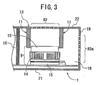
- Fig. 3 is an enlarged, partial cross-sectional view along - the line III-III in Fig. 1, which shows the inside structure of the CPU room (i.e., the first room) of the electronic apparatus according to the embodiment of Fig. 1.
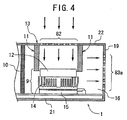
- Fig. 4 is an enlarged, partial cross-sectional view along the line III-III in Fig. 1, which schematically shows the state of the flowing air in the CPU room of the electronic apparatus according to the embodiment of Fig. 1.
- Fig. 5 is a schematic plan view of the electronic apparatus according to the embodiment of Fig. 1, which schematically shows the state of the flowing air in the whole casing of the apparatus.
- Figs. 1 and 2 schematically show an electronic apparatus 1 with a built-in CPU according to an embodiment of the invention, in which the apparatus 1 is constituted as a personal computer, one of the various information processing systems or apparatuses.
- the top wall of the casing is omitted to expose its inside structure.
- the front wall of the casing is omitted to expose its inside structure.
- the apparatus 1 of the embodiment comprises a casing 13 with a shape of approximately rectangular parallelepiped, which is formed by a front wall 17, a rear wall 18, a first (i.e., right) - side wall 19, a second (i.e., left) side wall 20, a bottom wall 21, and a top wall 22.
- a FDD unit 2 In the casing 13, a FDD unit 2, a CD-ROM unit 3, a first HDD unit 4, a second HDD unit 5, a power supply unit 6 with a built-in fan 7 are mounted at their respective locations near the front wall 17.
- the FDD unit 2, the CD-ROM unit 3, the first and second HDD units 4 and 5, and the power supply unit 6 are electronic units.
- the first side wall 19, which is located on the right side of Fig. 1, has a set of slits 81 for introducing the air from the outside into the casing 13.
- the set of slits 81 is located near the front wall 17 and is opposed to the right-hand sides of the CD-ROM drive 3 and the HDD drives 4 and 5.
- the set of slits 81 serves as a "second air inlet”.
- the second side wall 20, which is located on the left side of Fig. 1, has a set of slits 84 for discharging the air in the casing 13 to the outside.
- the set of slits 84 is located near the front wall 17 and is opposed to the power supply unit 6.
- the set of slits 84 serves as a "second air outlet”.
- the fan 7 is designed for cooling the power supply unit 6 and combined with the same. The fan 7 is fixed closely to the slits 84 and is faced to the same.
- the fan 7 is built in the power supply unit 6 in this embodiment, the fan 7 is mounted separately from the unit 6.
- the sets of the slits 81 and 84 are placed outside a CPU-room 16 explained in detail later.
- the slits 81 are placed to be opposed to the slit 84 while the FDD unit 2, the CD-ROM unit 3, the HDD units 4 and 5, and the power supply unit 6 are placed between the slits 81 and 84. Therefore, the air is introduced by the operation of the fan 7 into the casing 13 through the slits 81 (i.e., the second air inlet) and then, it flows to pass by the units 2, 3, 4, 5, and 6 toward the opposite slits 84. Thereafter, the air is discharged through the slits 84 (i.e., the second air outlet) from the casing 13 by the operation of the fan 7.
- the CPU room 16 is formed at the right-side rear corner of the casing 13, in which a CPU section 9 is placed.
- the room 16 is formed to separate the CPU section 9 from the units 2, 3, 4, 5 and 6, in other words, to isolate the CPU section 9 from these units 2 to 6.
- the CPU room 16 is defined by a L-shaped partition or wall 10 whose lateral ends are connected to the first side wall 19 and the rear wall 18, respectively.
- the vertical ends (i.e., the top and bottom ends) of the partition 10 are connected to the top and bottom walls 22 and 21, respectively.
- the room 16 has a horizontal cross section of approximately square in this embodiment, as shown in Fig. 1.
- the partition 10 is made of a heat-insulating material, which ensures the thermal separation of the CPU section 9 from the remaining section.
- Fig. 3 shows the detailed structure of the CPU section 9 and its neighborhood.
- the section 9 comprises a CPU 15 mounted on a specific circuit board (i.e., a mother board), a heat-radiating plate (i.e., heat sink) 14 integrated with the top of the CPU 15, and a cooling fan 12 attached to the plate 14.
- the circuit board is fixed to the bottom wall 21 of the casing 13.
- the plate 14 and the fan 12 are used to cool the CPU 15, in other words, to dissipate the heat generated in the CPU 15 on operation to the outside of the section 9.
- the heat-dissipating plate 14 may be fixed to the underlying circuit board with a known suitable attachment, not to be integrated with the CPU 15.
- the fan 12 may be fixed to the underlying CPU 15 or the circuit board with a known suitable attachment.
- a set of slits 82 is formed at the top plate 22 of the casing 13.
- the set of slits 82 which serves as a "first air inlet", is positioned to face the top of the fan 12 or CPU 15.
- the duct 11 has a horizontal cross section of approximately square in such a way as to entirely overlap with the CPU section 9.
- the duct 11 serves to form a vertical air path that interconnects the cooling fan 12 with the set of slits 82.
- the outside air can be directly introduced into the duct 11 through the slits 82 and then, it can be blown downward to the heat-radiating plate 14 through the fan 12.
- the air thus blown is expanded to the neighborhood of the section 9 in the room 16 by way of the gaps between the adjoining rod-shaped projections of the plate 14.
- a set of slits 83a which serves as a "first air outlet", is formed at the side plate 19 of the casing 13.
- the set of slits 83a is positioned to face the opposing side face of the CPU section 9 in the CPU room 16.
- a set of slits 83b which serves as the "first air outlet” as well, is formed at the rear wall 18 of the casing 13.
- the set of slits 83b is positioned to face the opposing rear face of the section 9 in the room 16.
- the outside air which has been introduced into the room 16 through the set of slits 82 and the duct 11, can be discharged to the outside through the sets of slits 83a and 83b by the blowing operation of the fan 12.
- Fig. 4 shows the state of the air flow in the CPU room 16.
- the hollow duct 11 is mounted vertically in the room 16 to interconnect the set of slits 82 with the cooling fan 12 of the CPU 15. Therefore, the outside air can be directly introduced into the room 16 with the fan 12 by way of the set of slits 82 and the duct 11 without passing through the remaining region of the casing 13, forming the vertical flow of air, as shown by the vertical arrows in Fig. 4. Then, the air thus introduced is blown to the heat-dissipating plate 14 and reflected by the same, resulting in the approximately horizontal flow of air, as shown by the horizontal arrows in Fig. 4. The air thus blown to the outside of the duct 11 in the room 16 is automatically pushed out to the outside of the casing 13 by way of the slits 83a and 83b directly.
- the heat-dissipating plate 14 Since the heat-dissipating plate 14 is contacted with the underlying CPU 15, the heat generated in the CPU 15 is easily conducted and sunken to the plate 14. The heat existing in the plate 14 is efficiently brought to the outside of the casing 13 by the flowing air.
- the CPU section 9 is located in the CPU room 16 and completely separated by the heat-insulating partition 10 from the units 2, 3, 4, 5, and 6. Therefore, the air introduced into the room 16 is brought out of the room 16 by way of the slots 83a and 83b along with the heat without contacting the units 2, 3, 4, 5, and 6. This - means that the heat generated by the CPU 15 never affects the units 2, 3, 4, 5, and 6 at all.
- Fig. 5 Shows the state of the air flow of the entire apparatus 1 of the embodiment.
- the FDD unit 2, the CD-ROM unit 3, the HDD units 4 and 5, and the power supply unit 6, which are located outside the CPU room 16 in the casing 13, are cooled in the following way:
- the outside air is introduced into the casing 13 through the set of slits 81 at the right side wall 19 of the casing 13. Then, the air thus introduced flows to pass by the CD-ROM and HDD units 3, 4, and 5, thereby removing the heat generated by these units 3 to 5. Thereafter, the air that has included the heat from the units 3 to 5 flows to pass by the FDD unit 2 and the power supply unit 6, thereby removing the heat generated by these units 2 and 6. The air that has included the heat from the units 2 to 6 is then. discharged through the set of slits 84 at the left side wall 20 of the casing 13 to the outside of the same. Accordingly, all the units 2, 3, 4, 5, and 6 are efficiently cooled by the air flow formed by the fan 7.
- the set of slits 82 for direct air introduction into the CPU room 16 defined by the heat-insulating partition 10 is formed at the top wall 22 of the casing 13.
- the sets of slits 83a and 83b for direct air discharge from the room 16 are formed at the first side wall 19 of the casing 13.
- the sets of slits 82 and 83a and 83b are dedicated to the air introduction and air discharge for the CPU 15.
- the FDD unit 2, the CD-ROM unit 3, the HDD units 4 and 5, and the power supply unit 6 are separated from the CPU section 9 with the partition 10 in the casing 13.
- the set of slits 81 for direct air introduction are formed at the first side wall 19 of the casing 13 to face the CD-ROM and HDD units 3, 4, and 5.
- the set of slits 84 for air discharge are formed at the second side wall 20 of the casing 13 to face the FDD unit 2 and the power supply unit 6.
- the CPU 15 can be cooled in the CPU room 16 by its dedicated air flow formed by the fan 12 while the units 2-to 6 can be cooled in the remaining part of the casing 13 by their dedicated air flow formed by the fan 7. This means that the CPU 15 can be cooled efficiently separately from the units 2 to 6.
- the units 2, 3, 4, and 5 and the power supply unit 6 with the fan 7 are placed in the area near the front wall 17.
- the sets of slits 81 and 84 are placed in the same area as the units 2 to 6. While the air introduced into the casing 13 through the slits 81 flows to the opposing slits 84, the air will contact all the units 2 to 6 and remove effectively the heat generated therein. As a result, these units 2 to 6 can be cooled effectively.
- the CPU section 9 is separated from the units 2 to 6 with the partition 10 made of a heat-insulating material. Therefore, there is no possibility that the heat generated in the CPU 15 affects badly the units 2 to 6 even if the mounting density of the units 2 to 6 in the casing 13 progresses and the heat amount generated by the CPU 15 increases. Since the duct 11 is additionally provided to interconnect the slots 82 with the fan 12 for the CPU 15, the cooling effect for the CPU section 9 is enhanced.
- the invention is not limited to the above-described embodiment. Any change or modification may be added to the embodiment within the spirit of the invention.
- the invention is applied to a personal computer in the above-described embodiment.
- the invention may be applied-to any other electronic apparatus or system having at least one built-in CPU than personal computers.
- two or more CPUs may be provided in the casing 13 according to the necessity.
- two or more CPUs may be confined in a CPU room to separate it from other electronic units and/or devices.
- two or more CPUs may be confined in their own CPU rooms, in which their CPU rooms may be defined with their own partitions.
- the CPU room 16 is located at one of the two rear corners of the casing 13, as explained in the above embodiment. This is because both the set of slits 83a and the set of slits 83b can be simultaneously formed for the room 16, thereby improving the cooling efficiency for the CPU 15. However, the set of slits 83a or the set of slits 83b may be formed for the room 16 if it is sufficient for a required cooling performance.
- the set of slits 83a and the set of slits 83b are provided for discharging the heated air existing in the CPU room 16 in the above-described embodiment.
- the invention is not limited to this.
- One of the set of slits 83a and the set of slits 83b may be removed.
- the duct 11 may be omitted if the top wall 22 is sufficiently close to the fan 12 of the CPU section 9. In this case, the air introduced into the room 16 is immediately blown to the heat-dissipating plate 14 through the fan 12 and therefore, a required cooling performance for the CPU 15 is realized without the duct 11.
- the set of slits 81 and the set of slits 84 are placed on a straight line in the above embodiment. This is to form an air flow from the slits 81 to the slits 84 while preventing the cooling performance of the air flow from decreasing. Therefore, if a required cooling performance for the units 2 to 6 is realized, the set of slits 81 and the set of slits 84 may not be placed on a straight line. In this case, it is sufficient that an air inlet and an air outlet are provided for cooling the units 2 to 6 outside the CPU room 16.
Landscapes
- Engineering & Computer Science (AREA)
- Theoretical Computer Science (AREA)
- Human Computer Interaction (AREA)
- Physics & Mathematics (AREA)
- General Engineering & Computer Science (AREA)
- General Physics & Mathematics (AREA)
- Cooling Or The Like Of Electrical Apparatus (AREA)
Abstract
Description
- The present invention relates to an electronic apparatus with a built-in CPU (Central Processing Unit). More particularly, the invention relates to an electronic apparatus with a built-in CPU that has a cooling structure for cooling the inside of the apparatus by effectively removing or dissipating the heat generated by the CPU.
- Conventionally, with an electronic information processing system or apparatus such as a personal computer, at least one cooling fan is mounted along with at least one built-in CPU. This is to discharge effectively the heat generated by the CPU to the outside of the casing. To meet this need, various techniques have been developed. Examples of these techniques are disclosed by the JP-A-10-93274, JP-A-10-124179 and JP-A-63-173111.
- The JP-A- 10-93274 discloses the cooling structure of information processing apparatuses or systems (e.g., personal computers) that increases the cooling efficiency while suppressing the noise caused by the cooling fan or fans. In this structure, a partition is provided in the casing having an air inlet and an air outlet, thereby forming a room to surround a cooling fan and heat generators (e.g., CPUs) mounted in the casing. The fan and the heat generators are almost separated by the partition from the other electronic units or devices mounted in the casing. The room is formed to communicate with the air inlet of the casing. The partition has an opening for allowing the flowing air generated by the cooling fan in the room to go out of the room. An air path is formed in the casing in such a way as to interconnect the opening of the partition with the air outlet of the casing. The air path is like a spiral while the opening of the partition is set as the spiral center.
- With the cooling structure of JP-A- 10-93274, the flowing air generated by the cooling fan in the room, which includes heat generated by the heat generators, will be emitted to the outside of the room through the opening of the partition. Thereafter, the flowing air will pass through the air path to the air outlet of the casing and then, it will go out of the casing through the air outlet. Preferably, the cooling fan is formed by a centrifugal fan.
- JP-A- 10-124179 discloses an information processing apparatus (e.g., a personal computer) with a cooling structure that improves the cooling efficiency. In this structure, a flexible disk drive (FDD) unit and a compact disk read-only memory (CD-ROM) unit are mounted in the casing in such a way as to be entirely overlapped with each other in their horizontal state. A hard disk drive (HDD) unit is mounted in its vertical state to be adjacent to the FDD and the CD-ROM units in the casing. A power supply unit is mounted in the rear of the FDD, CD-ROM, and HD units in the casing. Thus, a considerably wide space is formed near the power supply unit in the casing.
- A set of air inlets is only formed at the left-side wall of the casing near its front wall. An air flow is generated by the fan built in the power supply unit so as to extend from the set of air inlets to a set of air outlets formed at the rear wall of the casing. The air flow thus formed in the casing is like an L character. The flowing air will pass by not only the HDD unit but also the FDD and CD-ROM units, thereby cooling efficiently these units while suppressing the cooling noise.
- With the cooling structure of JP-A- 10-124179, the HDD, FDD, and CD-ROM units can be mounted on the right side in the casing near its front wall with the use of an appropriate mounting member. Thereafter, the power supply unit wider than the CD-ROM unit can be mounted in the casing. Moreover, the HDD, FDD, and CD-ROM units and the power supply unit can be efficiently cooled by the air introduced into the casing through the set of air inlets.
- The JP-A-63-173111 discloses a personal computer with a cooling structure that makes it possible to cool efficiently the inside of the computer with a single cooling fan and that decreases the noise and cost. In this computer, a disk unit, a power supply unit, a cooling fan, and a circuit unit are mounted in a casing. The disk unit, which is placed near the front wall of the casing, is designed in such a way that the air enters the inside of the unit and penetrates through the same. The power supply unit, which is placed in rear of the disk unit, is designed in such a way that the air enters the inside of the unit and penetrates through the same.
- The casing comprises an attachment plate for dividing the inner space of the casing into an upper first room and a lower second room, and a set of air inlets for introducing the outside air into the first and second rooms. The disk unit and the power supply unit are placed in the first room while the circuit unit is placed in the second room.
- The cooling fan discharges the inside air in the second room to the outside of the casing. At the same time, the fan discharges the inside air in the first room, which is introduced through the opening of the disk unit and the set of air inlets, to the outside of the casing by way of the inside of the power supply unit. Thus, the air introduced through the disk unit passes through the power supply unit, thereby improving the cooling efficiency.
- With the computer of JP-A-63-173111, due to the blowing action of the cooling fan, the power supply unit and the disk unit placed in the first room can be cooled and at the same time, the circuit unit placed in the second room can be cooled. Therefore, the inside of the casing can effectively be cooled with the single cooling fan. This means that satisfactory cooling effect is realized with a single cooling fan and thus, cooling noise and fabrication cost are lowered.
- In recent years, the mounting density of electronic devices and/or units in the casing has been progressing and at the same time, the heat amount generated in the casing has been increasing steadily with the improving performance of the CPU. Therefore, it has become considerably difficult to discharge efficiently the heat generated in the casing to the outside. In other words, there is an increasing danger that some of the heat generated by the CPU tends to be confined in the casing and as a result, the confined heat will apply bad effects to the other electronic devices and/or units mounted in the casing. In the near future, the above-described trend will be promoted more and accordingly, there will arise a serious problem how the heat generated by the CPU is efficiently discharged from the casing, in other words, how to cool the inside of the casing effectively.
- With the above-described technique disclosed by JP-A-10-93274, the CPU is almost separated by the partition from the other electronic units or devices in the casing in such as way that a spiral-shaped flow of air is formed in the casing. Therefore, the heat generated by the CPU is circulated by the air flow in the entire casing and then, discharged to the outside from the casing. As a result, there is a problem that the heat generated by the CPU tends to apply a bad effect to the other electronic units or devices, such as the HDD and FDD units, mounted in the casing.
- With the above-described techniques disclosed by JP-A- 10-124179 and JP-A-63-173111, the heat generated by the CPU is circulated by the air flow in the entire casing and then, discharged to the outside from the casing. As a result, the same problem as JP-A- 10-93274 will occur.
- Accordingly, an object of the present invention is to provide an electronic apparatus that prevents other electronic devices/units mounted in a casing along with a built-in CPU from being badly affected by the heat generated by the CPU even if the mounting density of electronic devices and/or units in the casing progresses and the heat amount generated by the CPU increases.
- Another object of the present invention is to provide an electronic apparatus that dissipates more efficiently the heat generated by a built-in CPU from the casing with a simple measure.
- The above objects together with others not specifically mentioned will become clear to those skilled in the art from the following description.
- An electronic apparatus according to the invention comprises:
- (a) a casing having a first air inlet and a first air-outlet;
- (b) at least one electronic device/unit mounted in the casing;
- (c) a CPU mounted in the casing;
the CPU cooperating with the at least one electronic device/unit to realize desired functions;
the CPU having a first fan for cooling the same; and - (d) a partition fixed in the casing in such a way as to form
a first room and a second room;
the CPU and the first fan being placed in the first room;
the at least one electronic device/unit being placed in the second room;
wherein the air is introduced into the first room through
the first air inlet with an operation of the first fan and then,
discharged from the first room through the first air outlet without
contacting the least one electronic device/unit. -
- With the electronic apparatus according to the invention, the casing has the first air inlet and the first air outlet. The CPU mounted in the casing has the first fan for cooling the CPU itself. The partition is fixed in the casing in such a way as to form the first room and the second room. The CPU and the first fan are placed in the first room while the at least one electronic device/unit is placed in the second room. The air is introduced into the first room of the casing through the first air inlet with the operation of the first fan and then, discharged from the first room through the first air outlet without contacting the least one electronic device/unit.
- As a result, even if the mounting density of the electronic devices and/or units in the casing progresses and the heat amount generated by the CPU increases, the at least one electronic device/unit is prevented from being badly affected by the heat-generated by the built-in CPU.
- Moreover, the air including the heat generated by the built-in CPU in the first room does not contact the least one electronic device/unit in the second room. The air in the first room is immediately discharged from the first room through the first air outlet. As a result, the heat generated by the CPU is dissipated more efficiently from the casing with a simple measure of fixing the partition in the casing.
- In a preferred embodiment of the apparatus according to the invention, a duct is additionally provided to interconnect the first fan for the CPU with the first air inlet in the first room. In this embodiment, there is an additional advantage that the cooling effect for the CPU is enhanced.
- In another preferred embodiment of the apparatus according to the invention, the partition has a heat-insulating property. For example, the partition is made of a heat-insulating material, or the partition is covered with a heat-insulating member or material. In this embodiment, there is an additional advantage that the effect of the heat generated by the CPU in the first room to the at least one electronic device/unit in the second room can be shielded or blocked almost completely.
- In still another preferred embodiment of the apparatus according to the invention, a second air inlet formed at the casing in the second room, a second air outlet formed at the casing in the second room to be opposite to the second air inlet, and a second fan mounted to face the second air outlet in the second room are additionally provided. The second air inlet is used to introduce the air into the second room. The second air outlet is used to discharge the air introduced into the second room to the outside of the casing in such a away as to contact the least one electronic device/unit. In this embodiment, there is an additional advantage that the least one electronic device/unit in the second room is cooled efficiently by the air flowing through the second room from the second air inlet to the second air outlet.
- In order that the present invention may be readily carried into effect, it will now be described with reference to the accompanying drawings.
- Fig. 1 is a schematic plan view showing the inside structure of an electronic apparatus according to an embodiment of the invention, in which the top wall of the casing and the electronic units/devices and parts mounted in the casing that has no relation to the invention are omitted for clarification.
- Fig. 2 is a schematic front view showing the inside structure of the electronic apparatus according to the embodiment of Fig. 1, in which the front wall of the casing is omitted.
- Fig. 3 is an enlarged, partial cross-sectional view along - the line III-III in Fig. 1, which shows the inside structure of the CPU room (i.e., the first room) of the electronic apparatus according to the embodiment of Fig. 1.
- Fig. 4 is an enlarged, partial cross-sectional view along the line III-III in Fig. 1, which schematically shows the state of the flowing air in the CPU room of the electronic apparatus according to the embodiment of Fig. 1.
- Fig. 5 is a schematic plan view of the electronic apparatus according to the embodiment of Fig. 1, which schematically shows the state of the flowing air in the whole casing of the apparatus.
- Preferred embodiments of the present invention will be described in detail below while referring to the drawings attached.
- Figs. 1 and 2 schematically show an electronic apparatus 1 with a built-in CPU according to an embodiment of the invention, in which the apparatus 1 is constituted as a personal computer, one of the various information processing systems or apparatuses. In Fig. 1, the top wall of the casing is omitted to expose its inside structure. In Fig. 2, the front wall of the casing is omitted to expose its inside structure.
- The apparatus 1 of the embodiment comprises a
casing 13 with a shape of approximately rectangular parallelepiped, which is formed by afront wall 17, arear wall 18, a first (i.e., right) -side wall 19, a second (i.e., left)side wall 20, abottom wall 21, and atop wall 22. - In the
casing 13, aFDD unit 2, a CD-ROM unit 3, afirst HDD unit 4, a second HDD unit 5, apower supply unit 6 with a built-infan 7 are mounted at their respective locations near thefront wall 17. TheFDD unit 2, the CD-ROM unit 3, the first andsecond HDD units 4 and 5, and thepower supply unit 6 are electronic units. - The
first side wall 19, which is located on the right side of Fig. 1, has a set ofslits 81 for introducing the air from the outside into thecasing 13. The set ofslits 81 is located near thefront wall 17 and is opposed to the right-hand sides of the CD-ROM drive 3 and the HDD drives 4 and 5. The set ofslits 81 serves as a "second air inlet". - The
second side wall 20, which is located on the left side of Fig. 1, has a set ofslits 84 for discharging the air in thecasing 13 to the outside. The set ofslits 84 is located near thefront wall 17 and is opposed to thepower supply unit 6. The set ofslits 84 serves as a "second air outlet". Thefan 7 is designed for cooling thepower supply unit 6 and combined with the same. Thefan 7 is fixed closely to theslits 84 and is faced to the same. - Needless to say, although the
fan 7 is built in thepower supply unit 6 in this embodiment, thefan 7 is mounted separately from theunit 6. - The sets of the
slits room 16 explained in detail later. - As seen from Fig. 1, the
slits 81 are placed to be opposed to theslit 84 while theFDD unit 2, the CD-ROM unit 3, theHDD units 4 and 5, and thepower supply unit 6 are placed between theslits fan 7 into thecasing 13 through the slits 81 (i.e., the second air inlet) and then, it flows to pass by theunits casing 13 by the operation of thefan 7. - The
CPU room 16 is formed at the right-side rear corner of thecasing 13, in which aCPU section 9 is placed. Theroom 16 is formed to separate theCPU section 9 from theunits CPU section 9 from theseunits 2 to 6. - The
CPU room 16 is defined by a L-shaped partition orwall 10 whose lateral ends are connected to thefirst side wall 19 and therear wall 18, respectively. The vertical ends (i.e., the top and bottom ends) of thepartition 10 are connected to the top andbottom walls room 16 has a horizontal cross section of approximately square in this embodiment, as shown in Fig. 1. Thepartition 10 is made of a heat-insulating material, which ensures the thermal separation of theCPU section 9 from the remaining section. - Fig. 3 shows the detailed structure of the
CPU section 9 and its neighborhood. As shown in Fig. 3, thesection 9 comprises aCPU 15 mounted on a specific circuit board (i.e., a mother board), a heat-radiating plate (i.e., heat sink) 14 integrated with the top of theCPU 15, and a coolingfan 12 attached to theplate 14. The circuit board is fixed to thebottom wall 21 of thecasing 13. Theplate 14 and thefan 12 are used to cool theCPU 15, in other words, to dissipate the heat generated in theCPU 15 on operation to the outside of thesection 9. - To maximize the heat-dissipating area or performance of the heat-dissipating
plate 14 without expanding its occupation area, several rod-shaped projections are formed on the upper surface of theplate 14. Thefan 12 is placed at the top of the projections of theplate 14. - The heat-dissipating
plate 14 may be fixed to the underlying circuit board with a known suitable attachment, not to be integrated with theCPU 15. Similarly, thefan 12 may be fixed to theunderlying CPU 15 or the circuit board with a known suitable attachment. These structures are well known and thus, no further explanation is presented here. - In the
CPU room 16, a set ofslits 82 is formed at thetop plate 22 of thecasing 13. The set ofslits 82, which serves as a "first air inlet", is positioned to face the top of thefan 12 orCPU 15. Ahollow duct 11, which is like a square pillar with-its top and bottom open, is fixed to the inner surface of thetop wall 22, as clearly shown in Fig. 3. Theduct 11 has a horizontal cross section of approximately square in such a way as to entirely overlap with theCPU section 9. Theduct 11 serves to form a vertical air path that interconnects the coolingfan 12 with the set ofslits 82. Thus, by the operation of the coolingfan 12, the outside air can be directly introduced into theduct 11 through theslits 82 and then, it can be blown downward to the heat-radiatingplate 14 through thefan 12. The air thus blown is expanded to the neighborhood of thesection 9 in theroom 16 by way of the gaps between the adjoining rod-shaped projections of theplate 14. - A set of
slits 83a, which serves as a "first air outlet", is formed at theside plate 19 of thecasing 13. The set ofslits 83a is positioned to face the opposing side face of theCPU section 9 in theCPU room 16. A set ofslits 83b, which serves as the "first air outlet" as well, is formed at therear wall 18 of thecasing 13. The set ofslits 83b is positioned to face the opposing rear face of thesection 9 in theroom 16. The outside air, which has been introduced into theroom 16 through the set ofslits 82 and theduct 11, can be discharged to the outside through the sets ofslits fan 12. - Thus, by the operation of the cooling
fan 12, "introduction of the outside air into theCPU room 16", "cooling of theCPU 15 by blowing the air thus introduced to theplate 14", and "discharge-or dissipation of the heat generated by theCPU 15" can be performed. - Fig. 4 shows the state of the air flow in the
CPU room 16. Thehollow duct 11 is mounted vertically in theroom 16 to interconnect the set ofslits 82 with the coolingfan 12 of theCPU 15. Therefore, the outside air can be directly introduced into theroom 16 with thefan 12 by way of the set ofslits 82 and theduct 11 without passing through the remaining region of thecasing 13, forming the vertical flow of air, as shown by the vertical arrows in Fig. 4. Then, the air thus introduced is blown to the heat-dissipatingplate 14 and reflected by the same, resulting in the approximately horizontal flow of air, as shown by the horizontal arrows in Fig. 4. The air thus blown to the outside of theduct 11 in theroom 16 is automatically pushed out to the outside of thecasing 13 by way of theslits - Since the heat-dissipating
plate 14 is contacted with the underlyingCPU 15, the heat generated in theCPU 15 is easily conducted and sunken to theplate 14. The heat existing in theplate 14 is efficiently brought to the outside of thecasing 13 by the flowing air. - The
CPU section 9 is located in theCPU room 16 and completely separated by the heat-insulatingpartition 10 from theunits room 16 is brought out of theroom 16 by way of theslots units CPU 15 never affects theunits - Fig. 5 Shows the state of the air flow of the entire apparatus 1 of the embodiment.
- Since the
CPU section 9 is separated from theunits partition 16, the heated air generated by the heat from theCPU 15 in theCPU room 16 is not circulated in the remaining region of thecasing 13. This means that the heated air by theCPU 15 is not contacted with theunits room 16 and thecasing 13 through theslits - The
FDD unit 2, the CD-ROM unit 3, theHDD units 4 and 5, and thepower supply unit 6, which are located outside theCPU room 16 in thecasing 13, are cooled in the following way: - By the operation of the cooling
fan 7 of thepower supply unit 6, the outside air is introduced into thecasing 13 through the set ofslits 81 at theright side wall 19 of thecasing 13. Then, the air thus introduced flows to pass by the CD-ROM andHDD units units 3 to 5. Thereafter, the air that has included the heat from theunits 3 to 5 flows to pass by theFDD unit 2 and thepower supply unit 6, thereby removing the heat generated by theseunits units 2 to 6 is then. discharged through the set ofslits 84 at theleft side wall 20 of thecasing 13 to the outside of the same. Accordingly, all theunits fan 7. - With the electronic apparatus 1 according to the embodiment of the invention, the
CPU section 9, which includes theCPU 15, the heat-dissipatingplate 14, and the coolingfan 12, is confined in theCPU room 16. The set ofslits 82 for direct air introduction into theCPU room 16 defined by the heat-insulatingpartition 10 is formed at thetop wall 22 of thecasing 13. At the same time, the sets ofslits room 16 are formed at thefirst side wall 19 of thecasing 13. Thus, the sets ofslits CPU 15. - On the other hand, the
FDD unit 2, the CD-ROM unit 3, theHDD units 4 and 5, and thepower supply unit 6 are separated from theCPU section 9 with thepartition 10 in thecasing 13. The set ofslits 81 for direct air introduction are formed at thefirst side wall 19 of thecasing 13 to face the CD-ROM andHDD units slits 84 for air discharge are formed at thesecond side wall 20 of thecasing 13 to face theFDD unit 2 and thepower supply unit 6. - Accordingly, the
CPU 15 can be cooled in theCPU room 16 by its dedicated air flow formed by thefan 12 while the units 2-to 6 can be cooled in the remaining part of thecasing 13 by their dedicated air flow formed by thefan 7. This means that theCPU 15 can be cooled efficiently separately from theunits 2 to 6. - Furthermore, the
units power supply unit 6 with thefan 7 are placed in the area near thefront wall 17. The sets ofslits units 2 to 6. While the air introduced into thecasing 13 through theslits 81 flows to the opposingslits 84, the air will contact all theunits 2 to 6 and remove effectively the heat generated therein. As a result, theseunits 2 to 6 can be cooled effectively. - The
CPU section 9 is separated from theunits 2 to 6 with thepartition 10 made of a heat-insulating material. Therefore, there is no possibility that the heat generated in theCPU 15 affects badly theunits 2 to 6 even if the mounting density of theunits 2 to 6 in thecasing 13 progresses and the heat amount generated by theCPU 15 increases. Since theduct 11 is additionally provided to interconnect theslots 82 with thefan 12 for theCPU 15, the cooling effect for theCPU section 9 is enhanced. - It is needless to say that the invention is not limited to the above-described embodiment. Any change or modification may be added to the embodiment within the spirit of the invention. For example, the invention is applied to a personal computer in the above-described embodiment. However, the invention may be applied-to any other electronic apparatus or system having at least one built-in CPU than personal computers.
- Although one
CPU 15 is provided in thecasing 13 in the above-described embodiment, two or more CPUs may be provided in thecasing 13 according to the necessity. In this case, two or more CPUs may be confined in a CPU room to separate it from other electronic units and/or devices. Alternately, two or more CPUs may be confined in their own CPU rooms, in which their CPU rooms may be defined with their own partitions. - It is preferred that the
CPU room 16 is located at one of the two rear corners of thecasing 13, as explained in the above embodiment. This is because both the set ofslits 83a and the set ofslits 83b can be simultaneously formed for theroom 16, thereby improving the cooling efficiency for theCPU 15. However, the set ofslits 83a or the set ofslits 83b may be formed for theroom 16 if it is sufficient for a required cooling performance. - The set of
slits 83a and the set ofslits 83b are provided for discharging the heated air existing in theCPU room 16 in the above-described embodiment. However, the invention is not limited to this. One of the set ofslits 83a and the set ofslits 83b may be removed. - The
duct 11 may be omitted if thetop wall 22 is sufficiently close to thefan 12 of theCPU section 9. In this case, the air introduced into theroom 16 is immediately blown to the heat-dissipatingplate 14 through thefan 12 and therefore, a required cooling performance for theCPU 15 is realized without theduct 11. - The set of
slits 81 and the set ofslits 84 are placed on a straight line in the above embodiment. This is to form an air flow from theslits 81 to theslits 84 while preventing the cooling performance of the air flow from decreasing. Therefore, if a required cooling performance for theunits 2 to 6 is realized, the set ofslits 81 and the set ofslits 84 may not be placed on a straight line. In this case, it is sufficient that an air inlet and an air outlet are provided for cooling theunits 2 to 6 outside theCPU room 16.
Claims (10)
- An electronic apparatus comprising:wherein the air is introduced into the first room through the first air inlet with an operation of the first fan and then, discharged from the first room through the first air outlet without contacting the least one electronic device/unit.(a) a casing having a first air inlet and a first air outlet;(b) at least one electronic device/unit mounted in the casing;(c) a CPU mounted in the casing;
the CPU cooperating with the at least one electronic device/unit to realize desired functions;
the CPU having a first fan for cooling the same; and(d) a partition fixed in the casing in such a way as to form a first room and a second room;
the CPU and the first fan being placed in the first room;
the at least one electronic device/unit being placed in the second room; - The apparatus according to claim 1, further comprising a duct provided to interconnect the first fan of the CPU and the first air inlet.
- The apparatus according to claim 1 or 2, wherein the partition has a heat-insulating property.
- The apparatus according to claim 1, 2 or 3, further comprising:wherein the second air inlet is used to introduce the air into the second room;a second air inlet formed at the casing in the second room;a second air outlet formed at the casing in the second room to be opposite to the second air inlet; anda second fan mounted to face the second air outlet in the second room;
and wherein the second air outlet is used to discharge the air introduced into the second room to the outside of the casing in such a away as to contact the least one electronic device/unit. - The apparatus according to claim 4, wherein the second air inlet and the second air outlet are approximately placed on a straight line.
- The apparatus according to claim 4, wherein the second air inlet is formed at a side wall of the casing and the second air outlet is formed at an opposite side wall of the casing.
- The apparatus according to claim 4 or 5, further comprising a duct provided to interconnect the first fan of the CPU and the first air inlet.
- The apparatus according to any one of claims 1, to 7, wherein the first room is located at one of the rear corners of the casing.
- The apparatus according to claim 8,
wherein the at least one electronic device/unit is located near a front wall of the casing. - The apparatus according to claim 8,
wherein the at least one electronic device/unit, the second air inlet, and the second air outlet are located near a front wall of the casing.
Applications Claiming Priority (2)
| Application Number | Priority Date | Filing Date | Title |
|---|---|---|---|
| JP2000369634A JP2002169626A (en) | 2000-12-05 | 2000-12-05 | Electronic equipment with built-in central processing unit |
| JP2000369634 | 2000-12-05 |
Publications (2)
| Publication Number | Publication Date |
|---|---|
| EP1213641A2 true EP1213641A2 (en) | 2002-06-12 |
| EP1213641A3 EP1213641A3 (en) | 2005-12-14 |
Family
ID=18839643
Family Applications (1)
| Application Number | Title | Priority Date | Filing Date |
|---|---|---|---|
| EP01128456A Withdrawn EP1213641A3 (en) | 2000-12-05 | 2001-12-05 | Electronic apparatus with CPU |
Country Status (3)
| Country | Link |
|---|---|
| US (1) | US6654242B2 (en) |
| EP (1) | EP1213641A3 (en) |
| JP (1) | JP2002169626A (en) |
Cited By (5)
| Publication number | Priority date | Publication date | Assignee | Title |
|---|---|---|---|---|
| WO2004043122A2 (en) | 2002-11-05 | 2004-05-21 | Medion Ag | Housing |
| DE10329821B3 (en) * | 2003-06-26 | 2004-11-25 | Schäfer Gehäusesysteme GmbH | Ventilated housing for computer central processing unit has ventilation shaft adjusted in position relative to housing wall opening dependent on main board microprocessor position |
| EP1445683A3 (en) * | 2003-02-10 | 2006-08-02 | Kabushiki Kaisha Toshiba | Electronic apparatus and method of cooling the electronic apparatus |
| EP1418489A3 (en) * | 2002-11-05 | 2007-09-19 | Medion AG | Computer with cooling device |
| US8559173B2 (en) | 2010-03-15 | 2013-10-15 | Panasonic Corporation | Electronic apparatus provided with cooling structure |
Families Citing this family (27)
| Publication number | Priority date | Publication date | Assignee | Title |
|---|---|---|---|---|
| JP4263493B2 (en) * | 2003-01-28 | 2009-05-13 | 富士通株式会社 | Casing, device unit and fan unit |
| DE20307981U1 (en) * | 2003-05-22 | 2003-09-11 | arctic-cooling GmbH, Pfäffikon | Axial fan for computers |
| US7518862B1 (en) * | 2005-01-27 | 2009-04-14 | Wms Gaming Inc. | Wagering game terminal with internal cooling |
| JP2007047998A (en) | 2005-08-09 | 2007-02-22 | Sony Corp | Electronic component cooling structure and information processing apparatus |
| JP4721822B2 (en) * | 2005-08-23 | 2011-07-13 | 株式会社日立製作所 | Information processing device |
| JP4499647B2 (en) * | 2005-10-07 | 2010-07-07 | 富士通株式会社 | Electronics |
| US7394653B2 (en) * | 2005-10-25 | 2008-07-01 | Shuttle Inc. | Heat dissipating system of multi-media computer |
| JP2007171536A (en) * | 2005-12-21 | 2007-07-05 | Kofu Casio Co Ltd | Liquid crystal display element |
| US20070221440A1 (en) * | 2006-03-24 | 2007-09-27 | Gilliland Don A | Air exhaust/inlet sound attenuation mechanism |
| JP2007265142A (en) * | 2006-03-29 | 2007-10-11 | Noritsu Koki Co Ltd | Image data print order receiving device |
| US7595985B2 (en) * | 2006-06-19 | 2009-09-29 | Panduit Corp. | Network cabinet with thermal air flow management |
| EP1895387A1 (en) * | 2006-08-28 | 2008-03-05 | Silver-Stone Technology Co., Ltd. | Heat dissipating apparatus of a computer system |
| JP4737639B2 (en) * | 2007-03-19 | 2011-08-03 | 株式会社安川電機 | COOLING DEVICE AND ELECTRONIC DEVICE HAVING THE SAME |
| US8144458B2 (en) * | 2007-06-13 | 2012-03-27 | Hewlett-Packard Development Company, L.P. | Component layout in an enclosure |
| CN101377705B (en) * | 2007-08-30 | 2012-08-29 | 鸿富锦精密工业(深圳)有限公司 | Computer |
| JP4821858B2 (en) * | 2009-01-21 | 2011-11-24 | パナソニック株式会社 | Equipment control device |
| JP5378863B2 (en) * | 2009-04-02 | 2013-12-25 | 株式会社ソニー・コンピュータエンタテインメント | Electronics |
| US9839155B2 (en) | 2012-05-16 | 2017-12-05 | Panduit Corp. | Thermal ducting system |
| IN2013CH04361A (en) * | 2013-09-26 | 2015-04-03 | Intel Corp | |
| CN104699195A (en) * | 2013-12-06 | 2015-06-10 | 鸿富锦精密工业(武汉)有限公司 | Computer case |
| US20170059263A1 (en) * | 2014-03-31 | 2017-03-02 | Intel Corporation | Sonic dust remediation |
| US11901264B2 (en) * | 2018-10-31 | 2024-02-13 | Sk Hynix Nand Product Solutions Corp. | Choked flow cooling |
| US11665849B2 (en) * | 2020-06-11 | 2023-05-30 | Abb Schweiz Ag | Fire shield for variable frequency drive enclosure |
| TWI763256B (en) * | 2021-01-15 | 2022-05-01 | 宏碁股份有限公司 | Heat dissipation system of portable electronic device |
| CN115151076A (en) * | 2021-03-29 | 2022-10-04 | 北京小米移动软件有限公司 | Electronic device |
| JP7431460B2 (en) * | 2022-01-18 | 2024-02-15 | 株式会社Nhvコーポレーション | power supply |
| WO2025035424A1 (en) * | 2023-08-16 | 2025-02-20 | Siemens Aktiengesellschaft | Industrial controller and industrial computer |
Family Cites Families (12)
| Publication number | Priority date | Publication date | Assignee | Title |
|---|---|---|---|---|
| JP2577731B2 (en) | 1987-01-13 | 1997-02-05 | 株式会社日立製作所 | Personal computer |
| US4949218A (en) * | 1989-02-01 | 1990-08-14 | Fujitsu Limited | Cabinet with built-in cooling system |
| US5493457A (en) * | 1991-10-18 | 1996-02-20 | Matsushita Electric Industrial Co., Ltd. | Optical disk apparatus with cooling arrangement |
| JPH1093274A (en) | 1996-09-13 | 1998-04-10 | Nec Corp | Structure for cooling electronic apparatus |
| JPH10124179A (en) | 1996-10-16 | 1998-05-15 | Hitachi Ltd | Information processing device |
| US5813243A (en) * | 1997-04-04 | 1998-09-29 | Micron Electronics, Inc. | Chambered forced cooling system |
| US6141213A (en) * | 1997-06-24 | 2000-10-31 | Sun Microsystems, Inc. | Computer with high airflow and low acoustic noise |
| US6113485A (en) * | 1997-11-26 | 2000-09-05 | Advanced Micro Devices, Inc. | Duct processor cooling for personal computer |
| JP2000112572A (en) * | 1998-09-30 | 2000-04-21 | Matsushita Electric Ind Co Ltd | Electronic equipment with heat dissipation structure |
| US6253834B1 (en) * | 1998-10-28 | 2001-07-03 | Hewlett-Packard Company | Apparatus to enhance cooling of electronic device |
| US6094346A (en) * | 1998-12-29 | 2000-07-25 | Intel Corporation | Processor assembly cooling cell |
| US6400567B1 (en) * | 2000-10-19 | 2002-06-04 | Fujitsu Network Communications, Inc. | Equipment enclosure having separate compartments cooled by separate cooling airflows |
-
2000
- 2000-12-05 JP JP2000369634A patent/JP2002169626A/en active Pending
-
2001
- 2001-12-04 US US10/000,399 patent/US6654242B2/en not_active Expired - Lifetime
- 2001-12-05 EP EP01128456A patent/EP1213641A3/en not_active Withdrawn
Non-Patent Citations (1)
| Title |
|---|
| None * |
Cited By (7)
| Publication number | Priority date | Publication date | Assignee | Title |
|---|---|---|---|---|
| WO2004043122A2 (en) | 2002-11-05 | 2004-05-21 | Medion Ag | Housing |
| EP1418489A3 (en) * | 2002-11-05 | 2007-09-19 | Medion AG | Computer with cooling device |
| EP1445683A3 (en) * | 2003-02-10 | 2006-08-02 | Kabushiki Kaisha Toshiba | Electronic apparatus and method of cooling the electronic apparatus |
| US7456751B2 (en) | 2003-02-10 | 2008-11-25 | Kabushiki Kaisha Toshiba | Electronic apparatus and method of cooling the electronic apparatus |
| DE10329821B3 (en) * | 2003-06-26 | 2004-11-25 | Schäfer Gehäusesysteme GmbH | Ventilated housing for computer central processing unit has ventilation shaft adjusted in position relative to housing wall opening dependent on main board microprocessor position |
| US8559173B2 (en) | 2010-03-15 | 2013-10-15 | Panasonic Corporation | Electronic apparatus provided with cooling structure |
| US9367102B2 (en) | 2010-03-15 | 2016-06-14 | Panasonic Intellectual Property Management Co., Ltd. | Mobile computing device |
Also Published As
| Publication number | Publication date |
|---|---|
| US6654242B2 (en) | 2003-11-25 |
| JP2002169626A (en) | 2002-06-14 |
| EP1213641A3 (en) | 2005-12-14 |
| US20020067595A1 (en) | 2002-06-06 |
Similar Documents
| Publication | Publication Date | Title |
|---|---|---|
| US6654242B2 (en) | Electronic apparatus with built-in CPU | |
| US5440450A (en) | Housing cooling system | |
| US7277286B2 (en) | Computers | |
| CN1983114B (en) | Ventilated computer chassis | |
| US5793608A (en) | Cooling system for enclosed electronic components | |
| US7382616B2 (en) | Cooling system for computer hardware | |
| EP0898220B1 (en) | Electronic apparatus with improved heatsink arrangement | |
| US6885555B2 (en) | Cooling system for electronic devices | |
| US6975509B2 (en) | Computing apparatus with cooling fan | |
| US6979772B2 (en) | Integrated heat dissipating enclosure for electronic product | |
| JP2002530901A (en) | Parallel cooling of high power devices in serially cooled environments | |
| BR112013026340B1 (en) | ELECTRONIC DEVICE | |
| CN115245060A (en) | Electronic device | |
| CN114828467B (en) | Computer devices, housings and water cooling devices | |
| TW201314425A (en) | Heat sink and electronic device using the same | |
| JPS63177588A (en) | Blower for devices arranged in rows on board | |
| JP2007047998A (en) | Electronic component cooling structure and information processing apparatus | |
| JP2000188492A (en) | Hybrid air cooler and electrical component having it | |
| JP7298216B2 (en) | Server cooling device, server system, and server cooling method | |
| CN103037664A (en) | Radiating device and electronic device using same | |
| CN115244686A (en) | Heat sinks and electronics | |
| JP2003152153A (en) | Cpu cooler, fan holder therefor and electronic instrument | |
| US20050189088A1 (en) | Circulation structure of heat dissipation device | |
| JPH07131953A (en) | Air cooling structure of power equipment | |
| KR200307396Y1 (en) | Cpu cooler |
Legal Events
| Date | Code | Title | Description |
|---|---|---|---|
| PUAI | Public reference made under article 153(3) epc to a published international application that has entered the european phase |
Free format text: ORIGINAL CODE: 0009012 |
|
| AK | Designated contracting states |
Kind code of ref document: A2 Designated state(s): AT BE CH CY DE DK ES FI FR GB GR IE IT LI LU MC NL PT SE TR |
|
| AX | Request for extension of the european patent |
Free format text: AL;LT;LV;MK;RO;SI |
|
| PUAL | Search report despatched |
Free format text: ORIGINAL CODE: 0009013 |
|
| AK | Designated contracting states |
Kind code of ref document: A3 Designated state(s): AT BE CH CY DE DK ES FI FR GB GR IE IT LI LU MC NL PT SE TR |
|
| AX | Request for extension of the european patent |
Extension state: AL LT LV MK RO SI |
|
| 17P | Request for examination filed |
Effective date: 20051115 |
|
| AKX | Designation fees paid |
Designated state(s): DE FR GB |
|
| 17Q | First examination report despatched |
Effective date: 20060207 |
|
| STAA | Information on the status of an ep patent application or granted ep patent |
Free format text: STATUS: THE APPLICATION IS DEEMED TO BE WITHDRAWN |
|
| 18D | Application deemed to be withdrawn |
Effective date: 20070913 |