EP1213574A2 - Lens meter with marking means and procedure and device for processing a spectacle lens - Google Patents
Lens meter with marking means and procedure and device for processing a spectacle lens Download PDFInfo
- Publication number
- EP1213574A2 EP1213574A2 EP01126225A EP01126225A EP1213574A2 EP 1213574 A2 EP1213574 A2 EP 1213574A2 EP 01126225 A EP01126225 A EP 01126225A EP 01126225 A EP01126225 A EP 01126225A EP 1213574 A2 EP1213574 A2 EP 1213574A2
- Authority
- EP
- European Patent Office
- Prior art keywords
- lens
- data
- processing
- optical
- measurement
- Prior art date
- Legal status (The legal status is an assumption and is not a legal conclusion. Google has not performed a legal analysis and makes no representation as to the accuracy of the status listed.)
- Granted
Links
Images




Classifications
-
- G—PHYSICS
- G01—MEASURING; TESTING
- G01M—TESTING STATIC OR DYNAMIC BALANCE OF MACHINES OR STRUCTURES; TESTING OF STRUCTURES OR APPARATUS, NOT OTHERWISE PROVIDED FOR
- G01M11/00—Testing of optical apparatus; Testing structures by optical methods not otherwise provided for
- G01M11/02—Testing optical properties
- G01M11/0207—Details of measuring devices
- G01M11/0214—Details of devices holding the object to be tested
-
- G—PHYSICS
- G01—MEASURING; TESTING
- G01B—MEASURING LENGTH, THICKNESS OR SIMILAR LINEAR DIMENSIONS; MEASURING ANGLES; MEASURING AREAS; MEASURING IRREGULARITIES OF SURFACES OR CONTOURS
- G01B11/00—Measuring arrangements characterised by the use of optical techniques
-
- G—PHYSICS
- G01—MEASURING; TESTING
- G01M—TESTING STATIC OR DYNAMIC BALANCE OF MACHINES OR STRUCTURES; TESTING OF STRUCTURES OR APPARATUS, NOT OTHERWISE PROVIDED FOR
- G01M11/00—Testing of optical apparatus; Testing structures by optical methods not otherwise provided for
- G01M11/02—Testing optical properties
- G01M11/0228—Testing optical properties by measuring refractive power
- G01M11/0235—Testing optical properties by measuring refractive power by measuring multiple properties of lenses, automatic lens meters
-
- G—PHYSICS
- G01—MEASURING; TESTING
- G01M—TESTING STATIC OR DYNAMIC BALANCE OF MACHINES OR STRUCTURES; TESTING OF STRUCTURES OR APPARATUS, NOT OTHERWISE PROVIDED FOR
- G01M11/00—Testing of optical apparatus; Testing structures by optical methods not otherwise provided for
- G01M11/02—Testing optical properties
- G01M11/0242—Testing optical properties by measuring geometrical properties or aberrations
- G01M11/0257—Testing optical properties by measuring geometrical properties or aberrations by analyzing the image formed by the object to be tested
- G01M11/0264—Testing optical properties by measuring geometrical properties or aberrations by analyzing the image formed by the object to be tested by using targets or reference patterns
Definitions
- the present invention relates to a method for processing a spectacle lens comprising a step of measuring a lens which comprises deriving optical information including a position of an optical reference point using a lens meter for measuring optical properties, including a prism value, of a spectacle lens and a step of processing which comprises using the optical information derived in the step of measuring a lens as a portion of data for processing, and to a lens meter therefor.
- a spectacle glass is prepared by processing an uncut spectacle lens (in general, a so-called round lens having a circular shape) into a shape fitting the shape of a spectacle frame and fitting the cut lens into the spectacle frame.
- the uncut round lens is prepared and supplied by a lens manufacturer based on the data of the prescription on the eye of the person who is to wear the spectacle glass (the dioptric power, the cylindrical dioptric power, the distance between the right and left eyes and the like other data), the data on the shape of the spectacle frame selected by the person who is to wear the spectacle glass and the layout information.
- Measurements of the round lens supplied from the lens manufacturer are conducted by the manufacturer using a lens meter.
- the position of the optical center and the cylinder axis are obtained and marks showing the position and the angle are placed on the lens.
- the marks are used as marks showing the position and the angle of attachment of a lens holder which is attached to the uncut lens before the processing as a jig used as the axis of rotation of the lens in the processing of the lens.
- an optical property such as the prism value is measured using a lens meter at a position estimated to be close to the optical center. The measurement is repeated at different estimated positions until the position where the obtained value becomes zero is found out and the found position is decided as the position of the optical center (for example, the specifications of Japanese Utility Model No. 2569718 and Japanese Utility Model Application Laid-Open No. Heisei 1(1989)-135344).
- a mark 600 is placed at the position of the optical center (O.C) of the spectacle lens and two marks 600a and 600b are placed at positions at both sides of the optical center on a straight line passing through the position of the optical center to show the cylinder axis and the like.
- the uncut lens has three marks.
- the prism value or the like is visually measured at a position considered to be close to the optical center using a lens meter so that the position where the value of the prism value is zero is found out. It takes a long time to find out the accurate position. Moreover, in the case of a plastic lens, sufficient care must be taken not to form scratches on the lens since the lens is moved on a processing table.
- the present invention has been made under the above circumstances and has an object of providing a method for processing a spectacle lens which enables marking at a point of measurement selected as desired easily and quickly without the risk of forming scratches on the lens, and to provide a lens meter therefor.
- the data of relative positions describing the relation between the position of a mark placed at the point of measurement selected as desired and the position of an optical reference point including the position of an optical center are saved. Therefore, when the position of the mark is detected for processing the lens and the above relative positions are read, the position of the optical center or the like relative to the detected position can become known immediately.
- the position of blocking can be decided based on the information derived as above and a lens holder can be attached so that the uncut lens can be processed. In accordance with the inventive method, it is sufficient in the step of measuring a lens that a mark is placed simply at a position selected as desired.
- Complicated operations such as measuring the prism value or the like at different positions using a lens meter and finding out the position where the value derived by the measurement becomes zero are not necessary. Therefore, the mark can be placed quickly and there is no possibility of forming scratches on the lens since the lens is not moved on the processing table.
- the method for processing a spectacle lens of one embodiment comprises a step of measuring a lens and a step of processing a lens as shown in Fig. 1.
- the step of measuring a lens using a round lens supplied by a lens manufacturer based on a specific prescription, optical properties such as dioptric powers are measured and confirmed using a lens meter, the position of an optical reference point such as the optical center and the cylinder axis are derived, marks showing the position and the angle are placed on the lens and the data of the positions are saved.
- the step of processing a lens comprises blocking a lens holder in which a lens holder which is a jig used as the axis of rotation in the processing of the lens is attached to the lens before the processing and then processing the lens.
- the marks placed in the step of measuring a lens are utilized for deciding the position of blocking in the step of blocking a lens holder. Since the step of processing a lens is conducted with using a conventional apparatus for processing a spectacle lens, the step of processing a lens will not be described in detail. The method for processing a spectacle lens and the lens meter described above will be described further in the following.
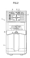
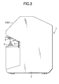
- a measurement table 3 for placing a lens for examination is disposed in a front portion of a main portion 2 of the lens meter 1. Behind the measurement table 3 (at an inner position of the lens meter 1), a portion for setting the position of a sample 4 for helping setting the position of the uncut lens 18 (Fig. 4) is disposed. Above the measurement table 3, a portion for holding a lens 5 is disposed. Behind the portion for holding a lens 5, a marking portion 6 for marking the light axis of the lens for examination is disposed.
- an operating panel portion 7 having switches and a power source, a display apparatus 8 for displaying the relative positions of the point of the measurement and the optical center of the lens for examination and another display apparatus 9 for displaying the results of the operation are disposed.
- FIG. 4 shows a diagram exhibiting an internal construction of a lens meter as an embodiment of the present invention, which comprises the optical system 10 for measurement and the portion 11 for information processing.
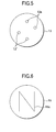
- the number 13 means a light source of the lens meter composed of four light emitting diodes (LED) 13a emitting light of an ultra-high luminance.
- Fig. 5 shows a diagram exhibiting the light source 13. As shown in Fig. 5, the four LED 13a are arranged at positions separated by the same distance from adjacent units so that the calculation which will be described later is simplified.
- the reference number 14 indicates a condenser lens and the rays from each LED 13a are arranged into parallel rays. This means that LED 13a is disposed at the focal point of the condenser lens 14.
- the reference number 15 indicates a target plate.
- Fig. 6 shows a diagram exhibiting the target plate 15.
- the target plate 15 has a slit pattern 15a having the shape of N and disposed between the condenser lens 12 and a collimator lens 16 in a manner such that the target plate can be moved by a pulse motor 17.
- the collimator lens 16 has the function of forming an image of the light source on the lens for examination 18 and arranging the rays forming the image of the slit pattern 15a into the parallel rays by the combined effect with the lens for examination 18.
- the lens for examination 18 is set at the measurement table 3 in a manner such that the optical center of the lens is placed at the same position as the position of the center of the optical system of measurement.
- the reference number 19 indicates an object lens and the parallel rays of the pattern 15a arranged by the collimator lens 16 and the lens for examination 18 is focused to form an image of the pattern 15a.
- the reference number 20 indicates an image sensor of a charge-coupled device (CCD) which is disposed at the focal point of the object lens 19 and detects the position of the pattern.
- CCD charge-coupled device
- the portion 11 for information processing has the functions of controlling the system in accordance with a specific program in cooperation with devices of a control substrate, a circuit for signal processing, a circuit for driving displays, a circuit for driving light sources, a circuit for driving a pulse motor, a circuit for numerical calculation and a circuit for driving a printer, conducting calculations such as calculation of the position of the optical center, preparing and memorizing data of relative positions of the optical center and the marking and recording the data into a specific recording medium or transferring the data to other instruments such as a computer.
- the amounts of the shift of the above patterns formed on the image sensor 20 from each of four LED 13a by the dioptric power (the power) of the lens for examination 18 which is placed between the collimator lens 16 and the object lens 19 and, after the target plate is moved, the amount of movement of the target plate 15 and the above amounts of the shift after the movement are used for-calculation by the circuit for numerical calculation.
- optical properties of the lens for examination such as the spherical power, the cylindrical power, the direction of the axis, the prism power and the direction of the base can be obtained and displayed.
- the prism value at the point of measurement can be measured by deriving the central coordinates of the pattern.
- the central coordinates of the pattern when the lens for examination 18 is set at the measurement table 3 is expressed as (x 1 , y 1 ) and the central coordinates of the pattern when the lens for examination 18 is not set at the measurement table 3 is expressed as (x 0 , y 0 ).
- (x 1 , y 1 ) in the new coordinates shows the prism value P itself at the point of measurement of the lens for examination 18.
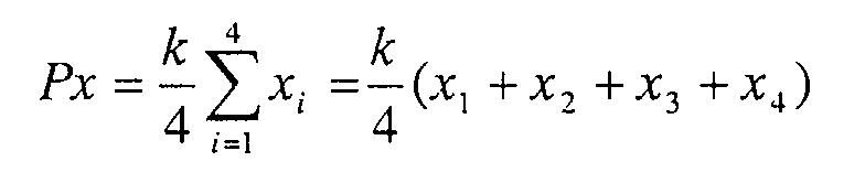
- the relation between the position of the point of the measurement and the position of the optical center of the lens for examination is derived from the prism value at the point of the measurement derived as described above by calculation described in the following.
- the prism value is represented by P
- the dioptric power of the lens is represented by D
- the distance between the position of the point of the measurement and the position of the optical center is represented by ⁇
- the prism value P, the components of the prism value P in the X-direction (Px) and in the Y-direction (Py), the angle ⁇ in the direction of the base of the prism, the spherical power and the cylindrical power of the lens for examination derived as described above are displayed on the display apparatus 9.
- the relation between the position of the point of the measurement and the position of the optical center is displayed on the display apparatus 8.
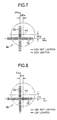
- Figs. 7 and 8 show diagrams describing embodiments of the display apparatus 8 which displays the relative positions of the point of the measurement and the optical center of the lens for examination.
- a number of light emitting diodes (LED) 22 are arranged in the X-direction and in the Y-direction in a manner such that the distance between the adjacent diodes is, for example, 1 mm.
- the diode disposed at the intersection of the X-axis and the Y-axis has a circular shape and other diodes have a rectangular shape. Based on the component of the prism value P in the X-direction Px and the dioptric power of the lens at the point of the measurement (the position of the circular LED in Fig.
- the component of the position of the optical center (shown in Fig. 7 by O.C) of the lens for examination in the X-direction with respect to the point of the measurement of the lens for examination is exhibited on the X-axis as the prism value DPx i .
- the component of the position of the optical center of the lens for examination in the Y-direction with respect to the point of the measurement of the lens for examination is exhibited on the Y-axis as the prism value DPy i .
- the display apparatus displays the values DPx and DPy showing the position of the optical center of the lens for examination with respect to the point of the measurement of the lens for examination as the prism value on the LED display of the cross type
- the shift of the position of the optical center with respect to the center of the optical system for the measurement can be displayed very accurately when the lens for examination has a very great dioptric power.
- the component of the position of the optical center of the lens for examination (shown in Fig. 8 by O.C) in the X-direction with respect to the position of the measurement of the lens for examination is exhibited on the X-axis as the distance ⁇ x.
- the component of the position of the optical center of the lens for examination with respect to the position of the measurement of the lens for examination is exhibited on the Y-axis as the distance ⁇ y.
- the display apparatus displays the components of the position of the optical center of the lens for examination in the X-direction and in the Y-direction with respect to the point of the measurement of the lens for the measurement as the distance on the LED display of the cross type
- the shift of the position of the optical center with respect to the center of the optical system for the measurement can be displayed very accurately when the lens for examination has a very small dioptric power.
- An example of the method for deriving the prism value is described in the above embodiment.
- the method for deriving the prism value is different depending on the slit pattern and the construction of the image sensor. Therefore, the prism value may be derived in accordance with other conventional methods such as the methods described in Japanese Patent Application Laid-Open No.
- the LED display having the cross arrangement is used as the display apparatus 8.
- other display apparatuses having X-and Y-coordinates such as liquid crystal displays and cathode ray tube displays may be used.
- the first mark 60 is placed as shown in Fig. 10 at the position of the measurement of the prism value by operating a marking lever 6a while the lens for examination is fixed at the position of the measurement of the prism value as shown in Fig. 9.
- the second mark 60a and the third mark 60b for showing the direction of the cylinder axis and the fourth mark 60c for recognizing vertical positions of the marks are simultaneously placed.
- the relations between the positions have been specified in advance and already known.
- the positions of the marks are different from the position of the optical center O.C since, in the present embodiment, the marks are not required to be placed at the position of the optical center but, instead, the lens for examination may be placed at a suitable position selected as desired and the first mark is placed at the position of the measurement decided by the position where the lens for examination is disposed (a free marking).
- a switch 6b for detecting the marking operation is disposed at the portion 6 for marking so that the switch 6b works at the moment when the mark is placed.
- the prism value derived by using the position of the mark as the position of the measurement and the relation between the position of the measurement calculated from the prism value and the position of the optical center of the lens for examination are memorized by the portion 11 of information processing, recorded on a specific recording medium or transferred to another instrument so that the information can be used in the processing of the lens in the next step, where necessary.
- a lens holder is attached for processing in the next step.
- a lens holder 30 held by an apparatus for attaching a lens holder 20 is pressed to the surface of the lens 18 fixed on a table 40 for fixing a lens and attached by adhesion with an adhesive sheet 30a.
- the lens holder is attached to the lens 18.
- the position of attaching the lens holder 30 to the lens 18 is the position of the rotational center during the processing and this position is used as the reference position for the processing.
- the lens holder is attached at the position of the optical center. It is also necessary that the lens holder be attached in a manner such that the cylinder axis of the lens is extending in the specific direction relative towards the reference position in the direction of rotation of the lens holder 30.
- the marks placed by the above marking operation are detected and the positions are specified.
- the positions of the marks relative to the reference position of the apparatus for attaching a lens holder 20 are specified.
- the positions of the marks is specified by an apparatus for image processing disposed in the apparatus for attaching a lens holder 20.
- the data which have been obtained in the step of measuring a lens, calculated and transferred i.e., the data showing the relation between the positions of the marks and the position of the optical center
- the lens holder 30 is attached to the position of the optical center of the lens 18 specified as described above. he lens to which the lens holder 30 has been attached is set to a conventional apparatus for processing a spectacle lens and processed.
- the method of the present invention comprises the step of measuring a lens in which the optical properties and the reference position of the spectacle lens are measured and the step of processing in which the lens is processed based on the optical information derived in the step of measuring a lens.
- the optical properties such as the prism value of the lens are measured using a position selected as desired in the uncut lens as the position of the measurement
- the optical reference position such as the position of the optical center is calculated from the result of the measurement
- the mark is placed at the obtained position and the relation between the position of the mark and the optical reference position is memorized, recorded or transferred to another instrument.
- the position of the mark is detected and specified, the reference position such as the position of the optical center is specified based on the position of the mark and the data which have been memorized, recorded or transferred and the lens is processed.
- the mark can be placed at a position selected as desired easily and quickly without the possibility of forming damages on the lens.
- the lens meter used therefor has the same advantages.
Landscapes
- Physics & Mathematics (AREA)
- General Physics & Mathematics (AREA)
- Chemical & Material Sciences (AREA)
- Analytical Chemistry (AREA)
- Geometry (AREA)
- Testing Of Optical Devices Or Fibers (AREA)
- Grinding And Polishing Of Tertiary Curved Surfaces And Surfaces With Complex Shapes (AREA)
- Eyeglasses (AREA)
Abstract
Description
- Fig. 1
- shows a diagram describing a method for processing a spectacle lens as an embodiment of the present invention;
- Fig. 2
- shows a front view of a lens meter as an embodiment of the present invention;
- Fig. 3
- shows a side view of a lens meter as an embodiment of the present invention;
- Fig. 4
- shows a diagram exhibiting an internal construction of a lens meter as an embodiment of the present invention;
- Fig. 5
- shows a diagram exhibiting a light source;
- Fig. 6
- shows a diagram exhibiting a target plate;
- Figs. 7 and 8
- show diagrams showing embodiments of a display apparatus;
- Fig. 9
- shows a diagram describing the operation of marking;
- Fig. 10
- shows a diagram exhibiting an embodiment of marks placed on the lens;
- Fig. 11
- shows an expanded view of the portion for marking;
- Fig. 12
- shows a diagram describing the operation of blocking a lens holder to a lens;
- Fig. 13
- shows a diagram illustrating a lens holder blocked to a lens;

Claims (5)
- A method for processing a spectacle lens comprising a step of measuring a lens which comprises deriving optical information including a position of an optical reference point using a lens meter for measuring optical properties, including a prism value of a spectacle lens and a step of processing which comprises using the optical information derived in the step of measuring a lens as a portion of data for the processing, wherein
the step of measuring a lens comprises:a step of measurement in which the optical properties, including the prism value of the lens are measured using a point selected as desired in an uncut lens as a point of measurement,a step of calculation in which the position of an optical reference point, including a position of an optical center, of the uncut lens is calculated based on data obtained in the step of measurement,a step of marking in which the mark is placed at the point of measurement or at a point placed at a specific relative position to the point of measurement,a step of processing data in which data of relative positions describing a relation between the position of the mark and the position of an optical reference point, including the position of an optical center, which is obtained in the step of calculation are prepared, anda step of saving in which the data of relative positions derived in the step of processing data is transferred to a later step in a manner such that the data can be read or saved into a memory medium or recording medium in a manner such that the data can be read. - A method for processing a spectacle lens as claimed in claim 1, wherein the step of processing comprises:detecting a mark on the uncut lens and measuring a position of the mark,reading the data of relative positions saved in the step of saving,specifying the position of an optical reference point, including the position of an optical center, of the uncut lens based on the data of relative positions derived as above and the position of the mark measured as above, andconducting necessary treatments for the processing using the position of an optical reference point specified as above as a reference point.
- A lens meter comprising:a portion for measuring optical properties in which the optical properties, including a prism value, of a lens are measured using a point selected as desired in a lens for measurement as a point of measurement;a portion for marking in which a mark is placed at the point of measurement or at a point placed at a specific relative position to the point of measurement; anda portion for information processing which is formed for realizing:a function of calculation for calculating a position of an optical reference point, including a position of an optical center, of an uncut lens based on data derived in the portion for measuring optical properties,a function of processing data for preparing data of relative positions describing a relation between a position of the mark and the position of an optical reference point, including the position of an optical center, which is derived by the function of calculation, anda function of saving data for transfering the data of relative positions derived by the function of processing data to a later step in a manner such that the data can be read or saves the data into a memory medium or recording medium in a manner such that the data can be read.
- An apparatus for processing a spectacle lens, which has the lens meter described in claim 3.
- Data of relative positions for processing a spectacle lens, derived by the function of processing data which is described in claim 3.
Applications Claiming Priority (2)
| Application Number | Priority Date | Filing Date | Title |
|---|---|---|---|
| JP2000376392 | 2000-12-11 | ||
| JP2000376392A JP4145012B2 (en) | 2000-12-11 | 2000-12-11 | Glasses lens processing method and lens meter |
Publications (3)
| Publication Number | Publication Date |
|---|---|
| EP1213574A2 true EP1213574A2 (en) | 2002-06-12 |
| EP1213574A3 EP1213574A3 (en) | 2003-03-12 |
| EP1213574B1 EP1213574B1 (en) | 2006-10-04 |
Family
ID=18845256
Family Applications (1)
| Application Number | Title | Priority Date | Filing Date |
|---|---|---|---|
| EP01126225A Expired - Lifetime EP1213574B1 (en) | 2000-12-11 | 2001-11-05 | Lens meter with marking means and procedure and device for processing a spectacle lens |
Country Status (7)
| Country | Link |
|---|---|
| US (1) | US6750959B2 (en) |
| EP (1) | EP1213574B1 (en) |
| JP (1) | JP4145012B2 (en) |
| KR (1) | KR100453524B1 (en) |
| CN (1) | CN1184504C (en) |
| AT (1) | ATE341754T1 (en) |
| DE (1) | DE60123558T2 (en) |
Cited By (4)
| Publication number | Priority date | Publication date | Assignee | Title |
|---|---|---|---|---|
| KR100453524B1 (en) * | 2000-12-11 | 2004-10-20 | 호야 가부시키가이샤 | A method for processing a spectacle lens, lens meter, an apparatus for processing a spectacle lens having lens meter |
| CN103413235A (en) * | 2013-08-23 | 2013-11-27 | 费淞 | Glasses assembling and marketing system based on Internet and marketing method |
| GB2580946A (en) * | 2019-01-31 | 2020-08-05 | Eyoto Group Ltd | Methods and apparatus for determining prism in a lens |
| CN111511502A (en) * | 2017-10-16 | 2020-08-07 | 国家视觉公司 | Integrated system and method for manufacturing, sorting and dispensing eyeglasses |
Families Citing this family (15)
| Publication number | Priority date | Publication date | Assignee | Title |
|---|---|---|---|---|
| DE10250856A1 (en) * | 2002-10-25 | 2004-05-13 | Carl Zeiss | Method and device for manufacturing optical glasses |
| US6951392B2 (en) * | 2003-07-09 | 2005-10-04 | 3M Innovative Properties Company | Lens having at least one lens centration mark and methods of making and using same |
| JP4186766B2 (en) * | 2003-09-12 | 2008-11-26 | セイコーエプソン株式会社 | Spectacle lens manufacturing system and spectacle lens manufacturing method |
| EP1762337A4 (en) * | 2004-06-30 | 2009-11-25 | Hoya Corp | Method of manufacturing spectacle lens |
| JP4812522B2 (en) * | 2006-06-02 | 2011-11-09 | Hoya株式会社 | Lens holder mounting accuracy confirmation system, lens mounting base and lens processing system |
| JP2014199303A (en) * | 2013-03-29 | 2014-10-23 | 株式会社ニデック | Spectacle lens measuring device, method of discriminating top and bottom of spectacle lens, and dot adapter disposed on the spectacle lens measuring device |
| JP2014233788A (en) * | 2013-05-31 | 2014-12-15 | 株式会社ニデック | Spectacle lens processing device and spectacle lens vertical direction detection program |
| CN103692295B (en) * | 2013-12-13 | 2016-05-25 | 上海现代先进超精密制造中心有限公司 | Optimized treatment method in a kind of ultraprecise convex cone mirror measurement-polishing update the system |
| EP3112837A1 (en) * | 2014-02-28 | 2017-01-04 | Hoya Lens Thailand Ltd. | Lens inspection apparatus and method for producing eyeglass lens |
| US10788393B2 (en) * | 2014-05-15 | 2020-09-29 | Emage Vision Pte. Ltd | System and method for inspecting opthalmic lenses |
| KR102149148B1 (en) * | 2018-11-12 | 2020-08-28 | 주식회사 휴비츠 | Apparatus and method for processing eye-glass lens sharing eye examining data |
| CN112880984A (en) * | 2021-03-08 | 2021-06-01 | 重庆远视科技有限公司 | Measurement guidance method, device, equipment and storage medium for lens lensometer |
| CN118575068A (en) | 2022-01-24 | 2024-08-30 | 123看股份有限公司 | Binocular automatic mirror detector |
| CN117400097B (en) * | 2023-10-19 | 2024-03-29 | 中山市光大光学仪器有限公司 | Prism angle processing control method and system |
| US20250283781A1 (en) * | 2024-03-06 | 2025-09-11 | Benz Research And Development Corp. | Method and system for determining an optic center of a lens blank |
Family Cites Families (19)
| Publication number | Priority date | Publication date | Assignee | Title |
|---|---|---|---|---|
| US4180325A (en) | 1977-07-05 | 1979-12-25 | Humphrey Instruments, Inc. | Lens meter with automated readout |
| JPS6017335A (en) | 1983-07-08 | 1985-01-29 | Nidetsuku:Kk | Auto-lens meter |
| JP2569718B2 (en) | 1988-05-02 | 1997-01-08 | 日本電装株式会社 | Clutch control device for compressor |
| JP2849569B2 (en) * | 1988-10-05 | 1999-01-20 | 株式会社トプコン | Lens meter |
| JPH03111160A (en) * | 1989-09-27 | 1991-05-10 | Topcon Corp | Optic axis adjuster |
| US5247341A (en) * | 1990-07-11 | 1993-09-21 | Nidek Co., Ltd. | Lensmeter for automatically measuring optical characteristic of a power lens |
| JP3011742B2 (en) * | 1990-07-11 | 2000-02-21 | 株式会社ニデック | Automatic lens meter |
| US5661816A (en) * | 1991-10-22 | 1997-08-26 | Optikos Corporation | Image analysis system |
| JP3066148B2 (en) * | 1991-10-31 | 2000-07-17 | 株式会社ニデック | Automatic lens meter |
| JP3226949B2 (en) * | 1992-02-03 | 2001-11-12 | 株式会社トプコン | Lens meter |
| US5489978A (en) * | 1992-11-05 | 1996-02-06 | Canon Kabushiki Kaisha | Lens measuring apparatus |
| JPH06249749A (en) * | 1993-02-26 | 1994-09-09 | Topcon Corp | Lens meter |
| JPH0915097A (en) * | 1995-06-26 | 1997-01-17 | Topcon Corp | Lens meter |
| JP3983329B2 (en) * | 1997-01-31 | 2007-09-26 | 株式会社トプコン | Lens identification device |
| JP3435019B2 (en) * | 1997-05-09 | 2003-08-11 | 株式会社ニデック | Lens characteristic measuring device and lens characteristic measuring method |
| JP4068233B2 (en) * | 1998-08-31 | 2008-03-26 | 株式会社ニデック | Cup mounting device |
| JP3115280B2 (en) * | 1998-11-20 | 2000-12-04 | 株式会社トプコン | Lens meter |
| US6671039B2 (en) * | 2000-06-22 | 2003-12-30 | Hoya Corporation | Spectacle lens image sensing processing apparatus and spectacle lens positioning method |
| JP4145012B2 (en) * | 2000-12-11 | 2008-09-03 | Hoya株式会社 | Glasses lens processing method and lens meter |
-
2000
- 2000-12-11 JP JP2000376392A patent/JP4145012B2/en not_active Expired - Fee Related
-
2001
- 2001-11-05 EP EP01126225A patent/EP1213574B1/en not_active Expired - Lifetime
- 2001-11-05 AT AT01126225T patent/ATE341754T1/en not_active IP Right Cessation
- 2001-11-05 DE DE60123558T patent/DE60123558T2/en not_active Expired - Lifetime
- 2001-12-10 KR KR10-2001-0077729A patent/KR100453524B1/en not_active Expired - Fee Related
- 2001-12-10 US US10/006,677 patent/US6750959B2/en not_active Expired - Fee Related
- 2001-12-11 CN CNB011435526A patent/CN1184504C/en not_active Expired - Fee Related
Cited By (5)
| Publication number | Priority date | Publication date | Assignee | Title |
|---|---|---|---|---|
| KR100453524B1 (en) * | 2000-12-11 | 2004-10-20 | 호야 가부시키가이샤 | A method for processing a spectacle lens, lens meter, an apparatus for processing a spectacle lens having lens meter |
| CN103413235A (en) * | 2013-08-23 | 2013-11-27 | 费淞 | Glasses assembling and marketing system based on Internet and marketing method |
| CN103413235B (en) * | 2013-08-23 | 2016-05-04 | 费淞 | A kind of glasses based on internet are equipped, marketing system and marketing method |
| CN111511502A (en) * | 2017-10-16 | 2020-08-07 | 国家视觉公司 | Integrated system and method for manufacturing, sorting and dispensing eyeglasses |
| GB2580946A (en) * | 2019-01-31 | 2020-08-05 | Eyoto Group Ltd | Methods and apparatus for determining prism in a lens |
Also Published As
| Publication number | Publication date |
|---|---|
| JP2002172549A (en) | 2002-06-18 |
| KR20020046206A (en) | 2002-06-20 |
| DE60123558D1 (en) | 2006-11-16 |
| ATE341754T1 (en) | 2006-10-15 |
| CN1359019A (en) | 2002-07-17 |
| US6750959B2 (en) | 2004-06-15 |
| US20020097389A1 (en) | 2002-07-25 |
| EP1213574B1 (en) | 2006-10-04 |
| JP4145012B2 (en) | 2008-09-03 |
| DE60123558T2 (en) | 2007-06-21 |
| EP1213574A3 (en) | 2003-03-12 |
| KR100453524B1 (en) | 2004-10-20 |
| CN1184504C (en) | 2005-01-12 |
Similar Documents
| Publication | Publication Date | Title |
|---|---|---|
| EP1213574B1 (en) | Lens meter with marking means and procedure and device for processing a spectacle lens | |
| US9645043B2 (en) | Method for checking the compliance of an optical characteristic of an ophthalmic lens and associated device | |
| US7538863B2 (en) | Device and a method of automatically detecting various characteristics of an ophthalmic lens | |
| JP3077054U (en) | Equipment for automatic installation of finishing blocks on lenses | |
| EP1167942B1 (en) | Spectacle lens image sensing processing apparatus | |
| US6888626B2 (en) | Device for automatically detecting characteristics of an ophthalmic lens and an automatic device for fitting a centering and drive peg incorporating it | |
| US7508502B2 (en) | Device for automatically detecting markings on an ophthalmic lens | |
| CN101297186B (en) | Lens Measuring Instrument | |
| JP4733105B2 (en) | Method for centering a spectacle lens in a centering-blocking device and associated centering-blocking device | |
| US7742158B2 (en) | Method and apparatus for locally measuring refractive characteristics of a lens in one or several specific points of said lens | |
| JP2003057149A (en) | Lens meter | |
| KR101213994B1 (en) | lens meter | |
| US8174687B2 (en) | Device and a method for measuring a camber geometrical characteristic of an ophthalmic lens | |
| JP2007155413A (en) | Lens meter | |
| JP2005241605A (en) | Lens meter | |
| JP6759937B2 (en) | Lens measuring device | |
| JPH0679600A (en) | Positioning device for spectacle lens | |
| KR102238740B1 (en) | Method and device for acquiring and computing data from an ophthalmic object | |
| JP2010085278A (en) | Lens meter | |
| JP2569718Y2 (en) | Optical center position display device for lens to be measured of lens meter | |
| JP2577700B2 (en) | Lens meter | |
| JPH11337445A (en) | Lens meter | |
| JP2829453B2 (en) | Lens meter | |
| WO2004088399A1 (en) | Lcd cell edge inspection apparatus and method thereof | |
| JPH11211616A (en) | Lens identification device |
Legal Events
| Date | Code | Title | Description |
|---|---|---|---|
| PUAI | Public reference made under article 153(3) epc to a published international application that has entered the european phase |
Free format text: ORIGINAL CODE: 0009012 |
|
| AK | Designated contracting states |
Kind code of ref document: A2 Designated state(s): AT BE CH CY DE DK ES FI FR GB GR IE IT LI LU MC NL PT SE TR |
|
| AX | Request for extension of the european patent |
Free format text: AL;LT;LV;MK;RO;SI |
|
| PUAL | Search report despatched |
Free format text: ORIGINAL CODE: 0009013 |
|
| AK | Designated contracting states |
Kind code of ref document: A3 Designated state(s): AT BE CH CY DE DK ES FI FR GB GR IE IT LI LU MC NL PT SE TR |
|
| AX | Request for extension of the european patent |
Extension state: AL LT LV MK RO SI |
|
| 17P | Request for examination filed |
Effective date: 20030328 |
|
| AKX | Designation fees paid |
Designated state(s): AT BE CH CY DE DK ES FI FR GB GR IE IT LI LU MC NL PT SE TR |
|
| 17Q | First examination report despatched |
Effective date: 20040820 |
|
| GRAP | Despatch of communication of intention to grant a patent |
Free format text: ORIGINAL CODE: EPIDOSNIGR1 |
|
| GRAS | Grant fee paid |
Free format text: ORIGINAL CODE: EPIDOSNIGR3 |
|
| GRAA | (expected) grant |
Free format text: ORIGINAL CODE: 0009210 |
|
| AK | Designated contracting states |
Kind code of ref document: B1 Designated state(s): AT BE CH CY DE DK ES FI FR GB GR IE IT LI LU MC NL PT SE TR |
|
| PG25 | Lapsed in a contracting state [announced via postgrant information from national office to epo] |
Ref country code: IT Free format text: LAPSE BECAUSE OF FAILURE TO SUBMIT A TRANSLATION OF THE DESCRIPTION OR TO PAY THE FEE WITHIN THE PRESCRIBED TIME-LIMIT;WARNING: LAPSES OF ITALIAN PATENTS WITH EFFECTIVE DATE BEFORE 2007 MAY HAVE OCCURRED AT ANY TIME BEFORE 2007. THE CORRECT EFFECTIVE DATE MAY BE DIFFERENT FROM THE ONE RECORDED. Effective date: 20061004 Ref country code: NL Free format text: LAPSE BECAUSE OF FAILURE TO SUBMIT A TRANSLATION OF THE DESCRIPTION OR TO PAY THE FEE WITHIN THE PRESCRIBED TIME-LIMIT Effective date: 20061004 Ref country code: FI Free format text: LAPSE BECAUSE OF FAILURE TO SUBMIT A TRANSLATION OF THE DESCRIPTION OR TO PAY THE FEE WITHIN THE PRESCRIBED TIME-LIMIT Effective date: 20061004 Ref country code: AT Free format text: LAPSE BECAUSE OF FAILURE TO SUBMIT A TRANSLATION OF THE DESCRIPTION OR TO PAY THE FEE WITHIN THE PRESCRIBED TIME-LIMIT Effective date: 20061004 Ref country code: LI Free format text: LAPSE BECAUSE OF FAILURE TO SUBMIT A TRANSLATION OF THE DESCRIPTION OR TO PAY THE FEE WITHIN THE PRESCRIBED TIME-LIMIT Effective date: 20061004 Ref country code: BE Free format text: LAPSE BECAUSE OF FAILURE TO SUBMIT A TRANSLATION OF THE DESCRIPTION OR TO PAY THE FEE WITHIN THE PRESCRIBED TIME-LIMIT Effective date: 20061004 Ref country code: CH Free format text: LAPSE BECAUSE OF FAILURE TO SUBMIT A TRANSLATION OF THE DESCRIPTION OR TO PAY THE FEE WITHIN THE PRESCRIBED TIME-LIMIT Effective date: 20061004 |
|
| REG | Reference to a national code |
Ref country code: GB Ref legal event code: FG4D |
|
| REG | Reference to a national code |
Ref country code: CH Ref legal event code: EP |
|
| PG25 | Lapsed in a contracting state [announced via postgrant information from national office to epo] |
Ref country code: IE Free format text: LAPSE BECAUSE OF NON-PAYMENT OF DUE FEES Effective date: 20061106 |
|
| REG | Reference to a national code |
Ref country code: IE Ref legal event code: FG4D |
|
| REF | Corresponds to: |
Ref document number: 60123558 Country of ref document: DE Date of ref document: 20061116 Kind code of ref document: P |
|
| PG25 | Lapsed in a contracting state [announced via postgrant information from national office to epo] |
Ref country code: MC Free format text: LAPSE BECAUSE OF NON-PAYMENT OF DUE FEES Effective date: 20061130 |
|
| PG25 | Lapsed in a contracting state [announced via postgrant information from national office to epo] |
Ref country code: DK Free format text: LAPSE BECAUSE OF FAILURE TO SUBMIT A TRANSLATION OF THE DESCRIPTION OR TO PAY THE FEE WITHIN THE PRESCRIBED TIME-LIMIT Effective date: 20070104 Ref country code: SE Free format text: LAPSE BECAUSE OF FAILURE TO SUBMIT A TRANSLATION OF THE DESCRIPTION OR TO PAY THE FEE WITHIN THE PRESCRIBED TIME-LIMIT Effective date: 20070104 |
|
| PG25 | Lapsed in a contracting state [announced via postgrant information from national office to epo] |
Ref country code: ES Free format text: LAPSE BECAUSE OF FAILURE TO SUBMIT A TRANSLATION OF THE DESCRIPTION OR TO PAY THE FEE WITHIN THE PRESCRIBED TIME-LIMIT Effective date: 20070115 |
|
| PG25 | Lapsed in a contracting state [announced via postgrant information from national office to epo] |
Ref country code: PT Free format text: LAPSE BECAUSE OF FAILURE TO SUBMIT A TRANSLATION OF THE DESCRIPTION OR TO PAY THE FEE WITHIN THE PRESCRIBED TIME-LIMIT Effective date: 20070316 |
|
| NLV1 | Nl: lapsed or annulled due to failure to fulfill the requirements of art. 29p and 29m of the patents act | ||
| REG | Reference to a national code |
Ref country code: CH Ref legal event code: PL |
|
| ET | Fr: translation filed | ||
| PLBE | No opposition filed within time limit |
Free format text: ORIGINAL CODE: 0009261 |
|
| STAA | Information on the status of an ep patent application or granted ep patent |
Free format text: STATUS: NO OPPOSITION FILED WITHIN TIME LIMIT |
|
| 26N | No opposition filed |
Effective date: 20070705 |
|
| PG25 | Lapsed in a contracting state [announced via postgrant information from national office to epo] |
Ref country code: GR Free format text: LAPSE BECAUSE OF FAILURE TO SUBMIT A TRANSLATION OF THE DESCRIPTION OR TO PAY THE FEE WITHIN THE PRESCRIBED TIME-LIMIT Effective date: 20070105 |
|
| PG25 | Lapsed in a contracting state [announced via postgrant information from national office to epo] |
Ref country code: LU Free format text: LAPSE BECAUSE OF NON-PAYMENT OF DUE FEES Effective date: 20061105 Ref country code: TR Free format text: LAPSE BECAUSE OF FAILURE TO SUBMIT A TRANSLATION OF THE DESCRIPTION OR TO PAY THE FEE WITHIN THE PRESCRIBED TIME-LIMIT Effective date: 20061004 |
|
| PG25 | Lapsed in a contracting state [announced via postgrant information from national office to epo] |
Ref country code: CY Free format text: LAPSE BECAUSE OF FAILURE TO SUBMIT A TRANSLATION OF THE DESCRIPTION OR TO PAY THE FEE WITHIN THE PRESCRIBED TIME-LIMIT Effective date: 20061004 |
|
| PGFP | Annual fee paid to national office [announced via postgrant information from national office to epo] |
Ref country code: FR Payment date: 20121130 Year of fee payment: 12 Ref country code: DE Payment date: 20121031 Year of fee payment: 12 |
|
| PGFP | Annual fee paid to national office [announced via postgrant information from national office to epo] |
Ref country code: GB Payment date: 20121031 Year of fee payment: 12 |
|
| GBPC | Gb: european patent ceased through non-payment of renewal fee |
Effective date: 20131105 |
|
| REG | Reference to a national code |
Ref country code: FR Ref legal event code: ST Effective date: 20140731 |
|
| PG25 | Lapsed in a contracting state [announced via postgrant information from national office to epo] |
Ref country code: DE Free format text: LAPSE BECAUSE OF NON-PAYMENT OF DUE FEES Effective date: 20140603 |
|
| REG | Reference to a national code |
Ref country code: DE Ref legal event code: R119 Ref document number: 60123558 Country of ref document: DE Effective date: 20140603 |
|
| PG25 | Lapsed in a contracting state [announced via postgrant information from national office to epo] |
Ref country code: GB Free format text: LAPSE BECAUSE OF NON-PAYMENT OF DUE FEES Effective date: 20131105 Ref country code: FR Free format text: LAPSE BECAUSE OF NON-PAYMENT OF DUE FEES Effective date: 20131202 |