EP1213533A1 - Enceinte contenant une platine support d'organes d'éclairage, notamment de tubes luminescents - Google Patents
Enceinte contenant une platine support d'organes d'éclairage, notamment de tubes luminescents Download PDFInfo
- Publication number
- EP1213533A1 EP1213533A1 EP01403045A EP01403045A EP1213533A1 EP 1213533 A1 EP1213533 A1 EP 1213533A1 EP 01403045 A EP01403045 A EP 01403045A EP 01403045 A EP01403045 A EP 01403045A EP 1213533 A1 EP1213533 A1 EP 1213533A1
- Authority
- EP
- European Patent Office
- Prior art keywords
- enclosure
- removable plate
- locking
- plate
- unlocking
- Prior art date
- Legal status (The legal status is an assumption and is not a legal conclusion. Google has not performed a legal analysis and makes no representation as to the accuracy of the status listed.)
- Granted
Links
Images
Classifications
-
- F—MECHANICAL ENGINEERING; LIGHTING; HEATING; WEAPONS; BLASTING
- F21—LIGHTING
- F21V—FUNCTIONAL FEATURES OR DETAILS OF LIGHTING DEVICES OR SYSTEMS THEREOF; STRUCTURAL COMBINATIONS OF LIGHTING DEVICES WITH OTHER ARTICLES, NOT OTHERWISE PROVIDED FOR
- F21V19/00—Fastening of light sources or lamp holders
- F21V19/0075—Fastening of light sources or lamp holders of tubular light sources, e.g. ring-shaped fluorescent light sources
- F21V19/008—Fastening of light sources or lamp holders of tubular light sources, e.g. ring-shaped fluorescent light sources of straight tubular light sources, e.g. straight fluorescent tubes, soffit lamps
- F21V19/009—Fastening of light sources or lamp holders of tubular light sources, e.g. ring-shaped fluorescent light sources of straight tubular light sources, e.g. straight fluorescent tubes, soffit lamps the support means engaging the vessel of the source
-
- F—MECHANICAL ENGINEERING; LIGHTING; HEATING; WEAPONS; BLASTING
- F21—LIGHTING
- F21V—FUNCTIONAL FEATURES OR DETAILS OF LIGHTING DEVICES OR SYSTEMS THEREOF; STRUCTURAL COMBINATIONS OF LIGHTING DEVICES WITH OTHER ARTICLES, NOT OTHERWISE PROVIDED FOR
- F21V15/00—Protecting lighting devices from damage
- F21V15/01—Housings, e.g. material or assembling of housing parts
- F21V15/015—Devices for covering joints between adjacent lighting devices; End coverings
-
- F—MECHANICAL ENGINEERING; LIGHTING; HEATING; WEAPONS; BLASTING
- F21—LIGHTING
- F21V—FUNCTIONAL FEATURES OR DETAILS OF LIGHTING DEVICES OR SYSTEMS THEREOF; STRUCTURAL COMBINATIONS OF LIGHTING DEVICES WITH OTHER ARTICLES, NOT OTHERWISE PROVIDED FOR
- F21V31/00—Gas-tight or water-tight arrangements
- F21V31/005—Sealing arrangements therefor
-
- F—MECHANICAL ENGINEERING; LIGHTING; HEATING; WEAPONS; BLASTING
- F21—LIGHTING
- F21Y—INDEXING SCHEME ASSOCIATED WITH SUBCLASSES F21K, F21L, F21S and F21V, RELATING TO THE FORM OR THE KIND OF THE LIGHT SOURCES OR OF THE COLOUR OF THE LIGHT EMITTED
- F21Y2103/00—Elongate light sources, e.g. fluorescent tubes
Definitions
- enclosure In the context of the invention, the term "enclosure” must be understood in its most general meaning. It concerns in particular, but not exclusively, tubular, glass, plastic or similar material enclosures, transparent or translucent. Such an enclosure is intended to contain a plate removable supporting one or more laps, for example of the tube type fluorescent above, and its usual accessories: electrical circuits, "starters”, etc. More generally, the removable plate can also support other types of lighting devices, tubular or not.
- Such a device is used in particular in buildings of commercial or industrial types.
- the enclosure is generally associated with sealing members, so that the circuits internal electrics do not present a danger to the external environment, especially in a humid atmosphere.
- the invention aims at the same time to overcome the drawbacks of the devices known art, some of which have just been recalled, and which meet the needs that are felt, namely in particular easy maintenance.
- the invention sets itself the goal of an enclosure comprising a plate removable supporting lighting elements allowing sliding longitudinal of this removable plate and comprising means of locking / unlocking.
- These locking / unlocking means are arranged in such a way that the removable plate can be manipulated by a single hand of an operator to operate the sliding, in one direction or another, and locking or unlocking.
- the removable plate is provided, at a first end, first guide means allowing longitudinal translation to the interior of the enclosure, advantageously constituted by a flat part whose external cut has a substantially dual shape of the wall section internal speaker.
- the second end of the enclosure and the end corresponding plate include means for locking / unlocking cooperating with each other.
- This second end of the enclosure further comprises, on its internal wall, second means for guiding the plate in its translational movement.
- Elastic means When the removable plate is fully inserted into the enclosure and locked, just push it towards said bottom wall and the move in said direction of travel. Elastic means continue to exert a force on the removable plate which pushes it towards the second end of the enclosure and authorizes both said unlocking and a subsequent longitudinal translation, until complete extraction.
- the enclosure is provided, on its two ends, of tight closing members.
- a cover is provided on the end in Regarding the locking / unlocking means, fixing means, advantageously by screw, cooperating with means of additional fixing secured on the second end of the plate removable.
- the main object of the invention is therefore an enclosure containing a removable plate, support for at least one lighting member, in particular of the type luminescent tube, and provided with a so-called bottom wall, said enclosure extending parallel to a so-called longitudinal axis and comprising an opening on the end opposite to said bottom wall, characterized in that it comprises first guide means subject to a first end of said support plate located opposite said bottom wall and the second guide means arranged on its second end, so as to allow a translational movement of said support plate along said axis longitudinal, in that it comprises elastic means, fixed to said first end of the support plate, exerting a repulsive force on it when it is fully inserted into said enclosure so that the said elastic means rest on said bottom wall, as it comprises first locking / unlocking means arranged at proximity of said opening cooperating with second means of locking / unlocking subject to a second end of the plate support, and in that these first and second means of locking / unlocking are arranged so that the unlocking takes place, from a so-called locked state, by
- enclosure containing a removable plate supporting organs lighting in a preferred embodiment, i.e. an enclosure intended for industrial applications containing one or more tube (s) fluorescent (s).
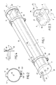
- Figure 1 illustrates, in perspective, an enclosure 1 of cylindrical shape and with a longitudinal axis ⁇ .
- the main part is composed of a tube 10 in transparent, or at least translucent material, for example plastic or glass.
- Means 5 are provided for fixing the enclosure 1 to a ceiling or to any suitable wall (not shown in the figure).
- these fixing means may consist of arches 50 comprising a trigger guard 51 allowing the actual attachment to any suitable surface: ceiling, wall, etc.
- these fixing means 5 can be removable.
- a closure 53 provided with a loop 530 and a hook 531 movable around an axis parallel to the ⁇ axis.
- the arch 50 for example of sheet steel
- the latter strongly encloses the wall outside of enclosure 1 when hook 531 is in the closed position (shown in solid lines in Figure 2).
- the open position of the hook 531 we can remove the loop 530 and release the hoops 50, which frees enclosure 1.
- the electrical energy required to supply the tube (s) fluorescent (s) is brought by a cable 33 which can pass through the wall 30 (or the wall 40, in a variant not shown), via a sealed pass-through 34.
- the removable plate 2 is provided, at its end opposite the bottom of the enclosure, a guide member 6, allowing this end to slide, by longitudinal translation, parallel to the axis ⁇ , inside the enclosure 1.
- a guide member 6 can be a simple flat piece 6 orthogonal to the plane 20 of the plate removable 2 and the cutting of which is dual or substantially dual in section internal of the tube 10, this section being in this case circular. The form exact will be specified below.
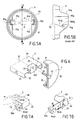
- elastic means 8 are provided which exert a repulsive force on the removable plate 2, as shown in more detail in FIG. 4 (in partial side view).
- these elastic means consist of a simple blade based on material with elastic properties, for example steel.
- This blade 8 is fixed by any conventional means 80, for example rivets or screws, to the wall of the flat part 6 or directly on the removable plate 2.
- any conventional means 80 for example rivets or screws, to the wall of the flat part 6 or directly on the removable plate 2.
- a room is provided ring 9, for example made of plastic, the dimensions of which are determined so that it can fit onto the end of the tube 10 of enclosure 1.
- ring 9 for example made of plastic, the dimensions of which are determined so that it can fit onto the end of the tube 10 of enclosure 1.
- a circular groove 91 of thickness equal to or slightly greater than the thickness of the wall of tube 1 of enclosure 1.
- two reinforcements are provided, which will be called arbitrarily straight 92d and left 92g.
- the ring 9 is fixed to the tube 10 of the enclosure 1, for example at using glue. It is naturally necessary to provide means of additional fixings (not shown), legs or others, allowing the screwing, in the absence of bonding.
- reinforcements, 92d and 92g are in turn provided with two grooves 93d and 93g, respectively.
- the difference, l, between the walls facing each groove, 93d and 93g, is chosen such that it allows the insertion of the removable plate 2 (in dotted lines in FIG. 5A).
- this length l is greater than the thickness e of the removable plate 2, so as to allow a movement of predetermined amplitude according to a direction substantially orthogonal to the axis ⁇ .
- the dimensions and the shape of the flat part 6 are such that they allow the insertion or extraction of the plate removable 2. They must in particular allow the passage of the end of this one between the reinforcements, 92 d and 92g, without having to dismantle the ring 9.
- the flat part 6 is given an oblong shape, so that it is in contact only on two ends, 60 and 61 ( Figure 3), from and on the other side of the plane 20 of the removable plate 2.
- the part 6 can be a truncated disc, because cut straight on its two sides, or a more complex set of parts with the same function. he it follows that it is in contact with the inert wall of the tube 10 on arcuate areas of circle, diametrically opposed.
- FIG. 7A In the detail figure 7A (in partial perspective), there is shown the removable plate 2 fully inserted in the tube 10 (position also shown in Figure 1).
- the spring 8 (FIG. 4) is compressed and exerts a maximum thrust force F on the removable plate 2.
- the horizontal walls 22 and 24 are then introduced into the spaces, 950d and 950g, arranged under the tabs 951d and 951g of the locking devices 95d and 95g.
- FIG. 7A only the locking member 95d and the horizontal wall 24 are visible.
- the aforementioned walls 22 and 24 form of which locking members complementary to the locking members 95g and 95d respectively.
- the plate removable 2 is removable in the manner just described, once locked ( Figure 7A), it becomes integral with the enclosure 2. It is therefore possible to secure the cover 3 closing the corresponding end of the tube 20 of enclosure 2.
- the fixing member associated with the cover 3 is constituted by a simple screw 32, with hexagonal head, in the embodiment described.
- the locking member is constituted by a block 25, of metal or plastic, the body of which is substantially rectangular parallelepiped. It is embedded at the end of the flat face 20 of the removable plate 2 and has two lateral wings allowing its attachment to this planar face 20, for example using screws 26.
- the block 25 has opposite before (that is to say facing the cover 3) a threaded hole 250 in which goes insert the end of screw 32.
- a peripheral seal can be provided 35 resting on the outer wall of the ring 9.
Landscapes
- Engineering & Computer Science (AREA)
- General Engineering & Computer Science (AREA)
- Fastening Of Light Sources Or Lamp Holders (AREA)
- Vessels And Coating Films For Discharge Lamps (AREA)
- Agricultural Chemicals And Associated Chemicals (AREA)
- Non-Portable Lighting Devices Or Systems Thereof (AREA)
- Securing Globes, Refractors, Reflectors Or The Like (AREA)
Abstract
Description
- la figure 1 illustre schématiquement un exemple de réalisation complet d'une enceinte selon l'invention ;
- la figure 2 illustre schématiquement des moyens permettant la fixation de l'enceinte de la figure 1 à une paroi support ;
- la figure 3 est une figure de détail illustrant, en perspective partielle, un exemple de réalisation d'un premier organe de guidage d'une platine amovible insérée dans l'enceinte de la figure 1 ;
- la figure 4 illustre un organe élastique constitué par une lame ressort mis en oeuvre dans l'enceinte dé la figure 1 ;
- les figures 5A et 5B sont des figures de détail illustrant des seconds organes de guidage et des organes de verrouillage/déverrouillage mis en oeuvre dans l'enceinte de la figure 1 ;
- la figure 6 illustre, en perspective partielle, de façon plus détaillée, la platine amovible de la figure 1 et un couvercle de fermeture de l'enceinte et ses organes de fixation ; et
- les figures 7A et 7B illustrent schématiquement les états verrouillé et déverrouillé de la platine de la figure 1, et des positions intermédiaires.
Claims (8)
- Enceinte contenant une platine amovible, support d'au moins un organe d'éclairage, notamment du type tube luminescent, et munie d'une paroi dite de fond, ladite enceinte s'étendant parallèlement à un axe dit longitudinal et comprenant une ouverture sur l'extrémité opposée à ladite paroi de fond, caractérisée en ce qu'elle comprend des premiers moyens de guidage (6) assujettis à une première extrémité de la dite platine support (2) située en vis-à-vis de ladite paroi de fond (41) et des seconds moyens de guidage (93d, 93g) disposés à sa seconde extrémité, de manière à autoriser un mouvement de translation de ladite platine support (20) le long du dit axe longitudinal (Δ), en ce qu'elle comprend des moyens élastiques (8), fixés à proximité de ladite première extrémité de la platine support (2), exerçant sur elle une force de répulsion (F) lorsqu'elle est entièrement insérée dans ladite enceinte (1) de manière à ce que les dits moyens élastiques (8) s'appuient sur ladite paroi de fond (41), en ce quelle comprend des premiers moyens de verrouillage/déverrouillage (95d, 95g) disposés à proximité de ladite ouverture coopérant avec des seconds moyens de verrouillage/déverrouillage (22, 24) assujettis à une seconde extrémité de la platine support (2), et en ce que ces premiers et seconds moyens de verrouillage/déverrouillage (95d, 95g, 22, 24) sont agencés de manière à ce que le déverrouillage s'effectue, à partir d'un état dit verrouillé, en exerçant une poussée sur ladite seconde extrémité de la platine amovible (2), suivant une direction parallèle au dit axe longitudinal (Δ), d'amplitude supérieure à ladite force de répulsion (F), la déplaçant (0-I) vers ladite paroi de fond (41), suivi un déplacement (I-II) suivant une direction orthogonale au dit axe longitudinal (Δ), de manière à désaccoupler les dits premiers (95d, 95g) et seconds moyens de verrouillage/déverrouillage (22, 24), et d'un relâchement de ladite poussée de manière à ce que ladite platine amovible (2) soit de nouveau soumise à ladite force de répulsion et entraínée vers ladite ouverture pour autoriser son extraction complète, et de manière à ce que le verrouillage s'effectue par un enchaínement d'actions en sens inverse, après insertion de ladite platine amovible dans ladite enceinte.
- Enceinte selon la revendication 1, caractérisée en ce que ladite platine amovible (2) ayant une face plane (20), support des dits organes d'éclairage (7) s'étendant parallèlement au dit axe longitudinal (Δ), les dits premiers moyens de guidage (93d, 93g) sont constitués par une pièce plate (6) sensiblement orthogonal à ladite paroi plane (20), de forme telle elle épouse des zones de la paroi interne de ladite enceinte (1, 10) disposées de part et d'autre de ladite face plane (20), de façon à guider ladite première extrémité de celle-ci lors des dits mouvements de translation.
- Enceinte selon la revendication 1, caractérisée en ce qu'elle est munie d'une pièce annulaire (9) emmanchée sur ladite extrémité d'embouchure et solidaire de celle-ci, en ce que cette pièce annulaire (9) comporte des renforts (92d, 92g) dans des zones opposées et en ce que les dits seconds moyens de guidage sont constitués par des gorges (93d, 93g) pratiquées dans ces renforts (92d, 92g), comportant une paroi de fond et deux parois en vis-à-vis, ces gorges étant destinées à recevoir entre les dites deux parois en vis-à-vis des extrémités latérales (21-22, 23-24) de ladite platine amovible (2), de manière à la guider lors des dits mouvements de translation, en coopération avec les dits premiers moyens de guidage (6).
- Enceinte selon la revendication 3, caractérisée en ce que ladite platine amovible (2) ayant une épaisseur déterminée e, les dites gorges (93d, 93g) ont une largeur déterminée ℓ, telle que la relation ℓ,>e soit vérifiée, de façon à permettre ledit déplacement de la platine amovible (2) suivant une direction orthogonale au dit axe longitudinal (Δ) lors du dit déverrouillage ou du dit verrouillage.
- Enceinte selon la revendication 1, caractérisée en ce que les dits moyens élastiques sont constitués par un matériau élastique (8), venant en butée contre ladite paroi de fond (41) et étant compressée lorsque ladite platine amovible (2) est insérée à fond dans ladite enceinte (1, 10), de manière à exercer sur celle-ci ladite force de répulsion (F) la repoussant vers ladite extrémité d'ouverture.
- Enceinte selon la revendication 3, caractérisée en ce que les dits premiers moyens de verrouillage/déverrouillage (95d, 95g) sont constitués par des languettes (950d, 950g) solidaires d'une des parois en vis-à-vis des dites gorges (93d, 93g) de ladite pièce annulaire (9) et ménageant des espaces libres (951d, 951g) entre elles-mêmes et les dites parois en vis-à-vis, les dites languettes (950d, 950g) étant orientées vers ladite paroi de fond (41), en ce que ladite platine amovible (2) comprend une face plane principale (20) s'étendant suivant ledit axe longitudinal (Δ), repliées latéralement à 90° de manière à former deux premières parois latérales longitudinales (21, 23), elles-mêmes repliées à 90° vers l'intérieur, de manière à former deux secondes parois longitudinales (22, 24), parallèles à ladite face plane principale (20), et en ce que les dits seconds moyens de verrouillage/déverrouillage sont constitués par l'extrémité des dites secondes parois longitudinales (22, 24), ledit verrouillage s'effectuant par encastrement de ces extrémités dans les dits espaces libres (951d, 951g).
- Enceinte selon la revendication 1, caractérisée en ce qu'elle comporte un couvercle (3) de fermeture de ladite extrémité d'ouverture et en ce qu'elle comprend des premiers moyens de fixations (32), solidaires du dit couvercle (3) et des seconds moyens de fixation (25), complémentaires des premiers, solidaires de ladite seconde extrémité de ladite platine amovible (20).
- Enceinte selon la revendication 7, caractérisé en ce que les dits premiers moyens de fixation comprennent une vis (32) traversant ledit couvercle (3) et les dits seconds moyens de fixation comprennent un bloc (25) sensiblement parallélépipédique rectangle, vissé sur ladite platine amovible (20), et comportant, sur une face en vis-à-vis du dit couvercle (3), un trou fileté (250) dans lequel peut s'insérer le corps de ladite vis (32).
Applications Claiming Priority (2)
| Application Number | Priority Date | Filing Date | Title |
|---|---|---|---|
| FR0016040 | 2000-12-08 | ||
| FR0016040A FR2817945B1 (fr) | 2000-12-08 | 2000-12-08 | Enceinte contenant une platine support d'organes d'eclairage, notamment de tubes luminescents |
Publications (2)
| Publication Number | Publication Date |
|---|---|
| EP1213533A1 true EP1213533A1 (fr) | 2002-06-12 |
| EP1213533B1 EP1213533B1 (fr) | 2007-02-14 |
Family
ID=8857457
Family Applications (1)
| Application Number | Title | Priority Date | Filing Date |
|---|---|---|---|
| EP01403045A Expired - Lifetime EP1213533B1 (fr) | 2000-12-08 | 2001-11-28 | Enceinte contenant une platine support d'organes d'éclairage, notamment de tubes luminescents |
Country Status (5)
| Country | Link |
|---|---|
| EP (1) | EP1213533B1 (fr) |
| AT (1) | ATE354063T1 (fr) |
| DE (1) | DE60126563T2 (fr) |
| ES (1) | ES2282219T3 (fr) |
| FR (1) | FR2817945B1 (fr) |
Cited By (3)
| Publication number | Priority date | Publication date | Assignee | Title |
|---|---|---|---|---|
| WO2010130047A1 (fr) * | 2009-05-15 | 2010-11-18 | Joseph Roy Laforge | Barrière de luminaire ou dispositif de fermeture |
| FR3040762A1 (fr) * | 2015-09-08 | 2017-03-10 | Soc D'exploitation Des Procedes Marechal | Luminaire longitudinal |
| FR3108707A1 (fr) * | 2020-03-26 | 2021-10-01 | Lumila | Dispositif d’éclairage à diodes électroluminescentes de forme allongée |
Families Citing this family (4)
| Publication number | Priority date | Publication date | Assignee | Title |
|---|---|---|---|---|
| DE202013101046U1 (de) | 2013-03-11 | 2013-03-15 | Alfred Pracht Lichttechnik Gmbh | Befestigung eines Leuchtmittels |
| DE202013101045U1 (de) | 2013-03-11 | 2013-03-18 | Alfred Pracht Lichttechnik Gmbh | Befestigung eines Leuchtmittels |
| FR3007103B1 (fr) | 2013-06-18 | 2017-10-06 | Mcsmbs | Dispositif d'eclairage |
| NL2011469C2 (en) * | 2013-09-19 | 2015-03-23 | Luminaid B V | Connector assembly for a line light module of a linear led system. |
Citations (3)
| Publication number | Priority date | Publication date | Assignee | Title |
|---|---|---|---|---|
| BE484621A (fr) * | ||||
| FR2316536A1 (fr) * | 1975-07-04 | 1977-01-28 | Sammode | Appareil d'eclairage a enveloppe tubulaire, notamment du type securite " e " |
| EP0935093A1 (fr) * | 1998-02-06 | 1999-08-11 | Societe d'Application des Methodes Modernes d'Eclairages Electriques Sammode | Appareil d'éclairage étanche |
-
2000
- 2000-12-08 FR FR0016040A patent/FR2817945B1/fr not_active Expired - Fee Related
-
2001
- 2001-11-28 ES ES01403045T patent/ES2282219T3/es not_active Expired - Lifetime
- 2001-11-28 AT AT01403045T patent/ATE354063T1/de not_active IP Right Cessation
- 2001-11-28 DE DE60126563T patent/DE60126563T2/de not_active Expired - Lifetime
- 2001-11-28 EP EP01403045A patent/EP1213533B1/fr not_active Expired - Lifetime
Patent Citations (3)
| Publication number | Priority date | Publication date | Assignee | Title |
|---|---|---|---|---|
| BE484621A (fr) * | ||||
| FR2316536A1 (fr) * | 1975-07-04 | 1977-01-28 | Sammode | Appareil d'eclairage a enveloppe tubulaire, notamment du type securite " e " |
| EP0935093A1 (fr) * | 1998-02-06 | 1999-08-11 | Societe d'Application des Methodes Modernes d'Eclairages Electriques Sammode | Appareil d'éclairage étanche |
Cited By (4)
| Publication number | Priority date | Publication date | Assignee | Title |
|---|---|---|---|---|
| WO2010130047A1 (fr) * | 2009-05-15 | 2010-11-18 | Joseph Roy Laforge | Barrière de luminaire ou dispositif de fermeture |
| FR3040762A1 (fr) * | 2015-09-08 | 2017-03-10 | Soc D'exploitation Des Procedes Marechal | Luminaire longitudinal |
| WO2017042458A1 (fr) * | 2015-09-08 | 2017-03-16 | Societe D'exploitation Des Procedes Marechal | Luminaire longitudinal |
| FR3108707A1 (fr) * | 2020-03-26 | 2021-10-01 | Lumila | Dispositif d’éclairage à diodes électroluminescentes de forme allongée |
Also Published As
| Publication number | Publication date |
|---|---|
| DE60126563T2 (de) | 2007-09-20 |
| EP1213533B1 (fr) | 2007-02-14 |
| ES2282219T3 (es) | 2007-10-16 |
| ATE354063T1 (de) | 2007-03-15 |
| FR2817945B1 (fr) | 2003-01-17 |
| FR2817945A1 (fr) | 2002-06-14 |
| DE60126563D1 (de) | 2007-03-29 |
Similar Documents
| Publication | Publication Date | Title |
|---|---|---|
| EP1178175B1 (fr) | Système de positionnement et d'assemblage d'une vitre sur un lève-vitre | |
| EP0793024B1 (fr) | Dispositif d'assemblage et de verrouillage de deux tubes téléscopiques | |
| EP2504102B1 (fr) | Enceinte pour dispositif de jonction étanche et dispositif de transfert aseptique. | |
| FR2750962A1 (fr) | Conteneur pour tranches, notamment de semiconducteurs et porte verrouillable pour ce conteneur | |
| EP1578675A1 (fr) | Bouchon de fermeture d'un flacon, a ouverture controlee | |
| FR2476329A1 (fr) | Boitier pour vues de meme format | |
| EP1621905A1 (fr) | Connecteur pour fibre optique | |
| EP1213533A1 (fr) | Enceinte contenant une platine support d'organes d'éclairage, notamment de tubes luminescents | |
| FR2626062A1 (fr) | Systeme de verrouillage et de deverrouillage d'une lampe sur un porte-lampe, plus particulierement pour un dispositif d'eclairage ou de signalisation notamment de vehicule automobile | |
| EP1882779A1 (fr) | Dispositif de verrouillage et de déverrouillage à l'aide d'une clé d'un tampon ou couvercle sur un cadre, notamment de regard de chaussée | |
| EP3437511B1 (fr) | Boîtier pour produit cosmétique | |
| FR2716299A1 (fr) | Connecteur flottant à verrouillage temporaire et son application au domaine spatial. | |
| EP2624956B1 (fr) | Cuvette de réaction pour appareil automatique d'analyse chimique ou biologique | |
| EP0223680A2 (fr) | Suspente pour faux plafond | |
| EP2839087B1 (fr) | Système de verrouillage à cliquet | |
| FR2590633A1 (fr) | Dispositif de fixation reglable, en particulier pour l'assemblage d'ecrans video | |
| FR2852794A1 (fr) | Boitier comportant un systeme de fermeture magnetique | |
| EP4239149B1 (fr) | Dispositif d'actionnement adapté à différents types d'élément de transmission pour serrure de porte | |
| FR2463987A1 (fr) | Dispositif de fixation rapide d'appareils electriques de commutation, en particulier de contacteurs, sur des profiles supports normalises | |
| FR2762127A1 (fr) | Dispositif pince-affiche | |
| FR2965840A1 (fr) | Mecanisme de porte coulissante | |
| FR3142210A1 (fr) | Système de casse pression entre deux locaux | |
| FR2626251A1 (fr) | Boite pour l'emballage et la presentation de conditionnement, notamment en verre, tels que bouteilles, flacons ou carafes | |
| FR2907484A1 (fr) | Dispositif de blocage en position fermee d'un vantail coulissant dans un dormant | |
| FR2710098A1 (fr) | Charnière femelle pour vantail ou analogue et son application à un système d'au moins deux paires de charnières. |
Legal Events
| Date | Code | Title | Description |
|---|---|---|---|
| PUAI | Public reference made under article 153(3) epc to a published international application that has entered the european phase |
Free format text: ORIGINAL CODE: 0009012 |
|
| AK | Designated contracting states |
Kind code of ref document: A1 Designated state(s): AT BE CH CY DE DK ES FI FR GB GR IE IT LI LU MC NL PT SE TR |
|
| AX | Request for extension of the european patent |
Free format text: AL;LT;LV;MK;RO;SI |
|
| 17P | Request for examination filed |
Effective date: 20021022 |
|
| AKX | Designation fees paid |
Designated state(s): AT BE CH CY DE DK ES FI FR GB GR IE IT LI LU MC NL PT SE TR |
|
| GRAP | Despatch of communication of intention to grant a patent |
Free format text: ORIGINAL CODE: EPIDOSNIGR1 |
|
| GRAC | Information related to communication of intention to grant a patent modified |
Free format text: ORIGINAL CODE: EPIDOSCIGR1 |
|
| GRAS | Grant fee paid |
Free format text: ORIGINAL CODE: EPIDOSNIGR3 |
|
| GRAA | (expected) grant |
Free format text: ORIGINAL CODE: 0009210 |
|
| AK | Designated contracting states |
Kind code of ref document: B1 Designated state(s): AT BE CH CY DE DK ES FI FR GB GR IE IT LI LU MC NL PT SE TR |
|
| PG25 | Lapsed in a contracting state [announced via postgrant information from national office to epo] |
Ref country code: FI Free format text: LAPSE BECAUSE OF FAILURE TO SUBMIT A TRANSLATION OF THE DESCRIPTION OR TO PAY THE FEE WITHIN THE PRESCRIBED TIME-LIMIT Effective date: 20070214 Ref country code: IE Free format text: LAPSE BECAUSE OF FAILURE TO SUBMIT A TRANSLATION OF THE DESCRIPTION OR TO PAY THE FEE WITHIN THE PRESCRIBED TIME-LIMIT Effective date: 20070214 Ref country code: DK Free format text: LAPSE BECAUSE OF FAILURE TO SUBMIT A TRANSLATION OF THE DESCRIPTION OR TO PAY THE FEE WITHIN THE PRESCRIBED TIME-LIMIT Effective date: 20070214 Ref country code: AT Free format text: LAPSE BECAUSE OF FAILURE TO SUBMIT A TRANSLATION OF THE DESCRIPTION OR TO PAY THE FEE WITHIN THE PRESCRIBED TIME-LIMIT Effective date: 20070214 |
|
| REG | Reference to a national code |
Ref country code: GB Ref legal event code: FG4D Free format text: NOT ENGLISH |
|
| RIN1 | Information on inventor provided before grant (corrected) |
Inventor name: DAVAL, BRUNO,C/O STE SAMMODE Inventor name: SAUVAGE, PHILIPPE,C/O STE SAMMODE Inventor name: ROUSSEAU, MARC,C/O STE SAMMODE |
|
| REG | Reference to a national code |
Ref country code: CH Ref legal event code: EP |
|
| REF | Corresponds to: |
Ref document number: 60126563 Country of ref document: DE Date of ref document: 20070329 Kind code of ref document: P |
|
| REG | Reference to a national code |
Ref country code: IE Ref legal event code: FG4D Free format text: LANGUAGE OF EP DOCUMENT: FRENCH |
|
| PG25 | Lapsed in a contracting state [announced via postgrant information from national office to epo] |
Ref country code: SE Free format text: LAPSE BECAUSE OF FAILURE TO SUBMIT A TRANSLATION OF THE DESCRIPTION OR TO PAY THE FEE WITHIN THE PRESCRIBED TIME-LIMIT Effective date: 20070514 |
|
| GBT | Gb: translation of ep patent filed (gb section 77(6)(a)/1977) |
Effective date: 20070523 |
|
| PG25 | Lapsed in a contracting state [announced via postgrant information from national office to epo] |
Ref country code: PT Free format text: LAPSE BECAUSE OF FAILURE TO SUBMIT A TRANSLATION OF THE DESCRIPTION OR TO PAY THE FEE WITHIN THE PRESCRIBED TIME-LIMIT Effective date: 20070716 |
|
| REG | Reference to a national code |
Ref country code: IE Ref legal event code: FD4D |
|
| REG | Reference to a national code |
Ref country code: ES Ref legal event code: FG2A Ref document number: 2282219 Country of ref document: ES Kind code of ref document: T3 |
|
| PLBE | No opposition filed within time limit |
Free format text: ORIGINAL CODE: 0009261 |
|
| STAA | Information on the status of an ep patent application or granted ep patent |
Free format text: STATUS: NO OPPOSITION FILED WITHIN TIME LIMIT |
|
| 26N | No opposition filed |
Effective date: 20071115 |
|
| PG25 | Lapsed in a contracting state [announced via postgrant information from national office to epo] |
Ref country code: GR Free format text: LAPSE BECAUSE OF FAILURE TO SUBMIT A TRANSLATION OF THE DESCRIPTION OR TO PAY THE FEE WITHIN THE PRESCRIBED TIME-LIMIT Effective date: 20070515 |
|
| PG25 | Lapsed in a contracting state [announced via postgrant information from national office to epo] |
Ref country code: CH Free format text: LAPSE BECAUSE OF NON-PAYMENT OF DUE FEES Effective date: 20071130 Ref country code: LI Free format text: LAPSE BECAUSE OF NON-PAYMENT OF DUE FEES Effective date: 20071130 |
|
| REG | Reference to a national code |
Ref country code: CH Ref legal event code: PL |
|
| PG25 | Lapsed in a contracting state [announced via postgrant information from national office to epo] |
Ref country code: CY Free format text: LAPSE BECAUSE OF FAILURE TO SUBMIT A TRANSLATION OF THE DESCRIPTION OR TO PAY THE FEE WITHIN THE PRESCRIBED TIME-LIMIT Effective date: 20070214 |
|
| PG25 | Lapsed in a contracting state [announced via postgrant information from national office to epo] |
Ref country code: LU Free format text: LAPSE BECAUSE OF NON-PAYMENT OF DUE FEES Effective date: 20071128 |
|
| PG25 | Lapsed in a contracting state [announced via postgrant information from national office to epo] |
Ref country code: TR Free format text: LAPSE BECAUSE OF FAILURE TO SUBMIT A TRANSLATION OF THE DESCRIPTION OR TO PAY THE FEE WITHIN THE PRESCRIBED TIME-LIMIT Effective date: 20070214 |
|
| REG | Reference to a national code |
Ref country code: FR Ref legal event code: CA Effective date: 20120614 |
|
| REG | Reference to a national code |
Ref country code: FR Ref legal event code: PLFP Year of fee payment: 15 |
|
| REG | Reference to a national code |
Ref country code: FR Ref legal event code: PLFP Year of fee payment: 16 |
|
| REG | Reference to a national code |
Ref country code: FR Ref legal event code: PLFP Year of fee payment: 17 |
|
| REG | Reference to a national code |
Ref country code: FR Ref legal event code: PLFP Year of fee payment: 18 |
|
| PGFP | Annual fee paid to national office [announced via postgrant information from national office to epo] |
Ref country code: FR Payment date: 20200928 Year of fee payment: 20 |
|
| PGFP | Annual fee paid to national office [announced via postgrant information from national office to epo] |
Ref country code: NL Payment date: 20201014 Year of fee payment: 20 |
|
| PGFP | Annual fee paid to national office [announced via postgrant information from national office to epo] |
Ref country code: GB Payment date: 20201118 Year of fee payment: 20 Ref country code: ES Payment date: 20201221 Year of fee payment: 20 Ref country code: IT Payment date: 20201112 Year of fee payment: 20 Ref country code: MC Payment date: 20201021 Year of fee payment: 20 Ref country code: DE Payment date: 20201109 Year of fee payment: 20 |
|
| PGFP | Annual fee paid to national office [announced via postgrant information from national office to epo] |
Ref country code: BE Payment date: 20201116 Year of fee payment: 20 |
|
| REG | Reference to a national code |
Ref country code: DE Ref legal event code: R071 Ref document number: 60126563 Country of ref document: DE |
|
| REG | Reference to a national code |
Ref country code: NL Ref legal event code: MK Effective date: 20211127 |
|
| REG | Reference to a national code |
Ref country code: GB Ref legal event code: PE20 Expiry date: 20211127 |
|
| REG | Reference to a national code |
Ref country code: BE Ref legal event code: MK Effective date: 20211128 |
|
| PG25 | Lapsed in a contracting state [announced via postgrant information from national office to epo] |
Ref country code: GB Free format text: LAPSE BECAUSE OF EXPIRATION OF PROTECTION Effective date: 20211127 |
|
| REG | Reference to a national code |
Ref country code: ES Ref legal event code: FD2A Effective date: 20220405 |
|
| PG25 | Lapsed in a contracting state [announced via postgrant information from national office to epo] |
Ref country code: ES Free format text: LAPSE BECAUSE OF EXPIRATION OF PROTECTION Effective date: 20211129 |