EP1212188B1 - Uv-illumination device - Google Patents
Uv-illumination device Download PDFInfo
- Publication number
- EP1212188B1 EP1212188B1 EP00943875A EP00943875A EP1212188B1 EP 1212188 B1 EP1212188 B1 EP 1212188B1 EP 00943875 A EP00943875 A EP 00943875A EP 00943875 A EP00943875 A EP 00943875A EP 1212188 B1 EP1212188 B1 EP 1212188B1
- Authority
- EP
- European Patent Office
- Prior art keywords
- lamp
- illuminating device
- radiation
- mould
- optical fibre
- Prior art date
- Legal status (The legal status is an assumption and is not a legal conclusion. Google has not performed a legal analysis and makes no representation as to the accuracy of the status listed.)
- Expired - Lifetime
Links
Images
Classifications
-
- B—PERFORMING OPERATIONS; TRANSPORTING
- B29—WORKING OF PLASTICS; WORKING OF SUBSTANCES IN A PLASTIC STATE IN GENERAL
- B29C—SHAPING OR JOINING OF PLASTICS; SHAPING OF MATERIAL IN A PLASTIC STATE, NOT OTHERWISE PROVIDED FOR; AFTER-TREATMENT OF THE SHAPED PRODUCTS, e.g. REPAIRING
- B29C35/00—Heating, cooling or curing, e.g. crosslinking or vulcanising; Apparatus therefor
- B29C35/02—Heating or curing, e.g. crosslinking or vulcanizing during moulding, e.g. in a mould
- B29C35/08—Heating or curing, e.g. crosslinking or vulcanizing during moulding, e.g. in a mould by wave energy or particle radiation
- B29C35/0888—Heating or curing, e.g. crosslinking or vulcanizing during moulding, e.g. in a mould by wave energy or particle radiation using transparant moulds
-
- B—PERFORMING OPERATIONS; TRANSPORTING
- B29—WORKING OF PLASTICS; WORKING OF SUBSTANCES IN A PLASTIC STATE IN GENERAL
- B29D—PRODUCING PARTICULAR ARTICLES FROM PLASTICS OR FROM SUBSTANCES IN A PLASTIC STATE
- B29D11/00—Producing optical elements, e.g. lenses or prisms
- B29D11/00009—Production of simple or compound lenses
- B29D11/00038—Production of contact lenses
- B29D11/00125—Auxiliary operations, e.g. removing oxygen from the mould, conveying moulds from a storage to the production line in an inert atmosphere
- B29D11/00134—Curing of the contact lens material
-
- B—PERFORMING OPERATIONS; TRANSPORTING
- B29—WORKING OF PLASTICS; WORKING OF SUBSTANCES IN A PLASTIC STATE IN GENERAL
- B29D—PRODUCING PARTICULAR ARTICLES FROM PLASTICS OR FROM SUBSTANCES IN A PLASTIC STATE
- B29D11/00—Producing optical elements, e.g. lenses or prisms
- B29D11/00009—Production of simple or compound lenses
- B29D11/00432—Auxiliary operations, e.g. machines for filling the moulds
- B29D11/00442—Curing the lens material
-
- G—PHYSICS
- G02—OPTICS
- G02B—OPTICAL ELEMENTS, SYSTEMS OR APPARATUS
- G02B6/00—Light guides; Structural details of arrangements comprising light guides and other optical elements, e.g. couplings
- G02B6/24—Coupling light guides
- G02B6/42—Coupling light guides with opto-electronic elements
- G02B6/4298—Coupling light guides with opto-electronic elements coupling with non-coherent light sources and/or radiation detectors, e.g. lamps, incandescent bulbs, scintillation chambers
-
- B—PERFORMING OPERATIONS; TRANSPORTING
- B29—WORKING OF PLASTICS; WORKING OF SUBSTANCES IN A PLASTIC STATE IN GENERAL
- B29C—SHAPING OR JOINING OF PLASTICS; SHAPING OF MATERIAL IN A PLASTIC STATE, NOT OTHERWISE PROVIDED FOR; AFTER-TREATMENT OF THE SHAPED PRODUCTS, e.g. REPAIRING
- B29C35/00—Heating, cooling or curing, e.g. crosslinking or vulcanising; Apparatus therefor
- B29C35/02—Heating or curing, e.g. crosslinking or vulcanizing during moulding, e.g. in a mould
- B29C35/08—Heating or curing, e.g. crosslinking or vulcanizing during moulding, e.g. in a mould by wave energy or particle radiation
- B29C35/0805—Heating or curing, e.g. crosslinking or vulcanizing during moulding, e.g. in a mould by wave energy or particle radiation using electromagnetic radiation
- B29C2035/0827—Heating or curing, e.g. crosslinking or vulcanizing during moulding, e.g. in a mould by wave energy or particle radiation using electromagnetic radiation using UV radiation
-
- B—PERFORMING OPERATIONS; TRANSPORTING
- B29—WORKING OF PLASTICS; WORKING OF SUBSTANCES IN A PLASTIC STATE IN GENERAL
- B29L—INDEXING SCHEME ASSOCIATED WITH SUBCLASS B29C, RELATING TO PARTICULAR ARTICLES
- B29L2011/00—Optical elements, e.g. lenses, prisms
- B29L2011/0016—Lenses
- B29L2011/0041—Contact lenses
Abstract
Description
- The invention relates to a method and device for crosslinking a biocompatible, polymerisable material in order to produce an ophthalmic moulding, especially an ophthalmic lens, particularly a contact lens.
- Contact lenses, which are to be manufactured economically in large unit numbers, are preferably manufactured by the so-called mould or full-mould process. In these processes, the lenses are manufactured into their final shape between two mould halves, so that there is no need to subsequently finish the surfaces of the lenses, nor to finish the edges. Mould processes are described for example in PCT patent application no. WO/87/04390 or in EP-A 0 367.513.
- The contact lenses produced in this manner are moulded parts having little mechanical stability and a water content of more than 60 % by weight. After manufacture, the lens is inspected, then packed and subjected to heat sterilisation at 121°C in an autoclave.
- In these known mould processes, the geometry of the contact lenses to be manufactured is defined by the mould cavity. The edge of the contact lens is likewise formed by the mould which normally consists of two mould halves. The geometry of the edge is defined by the contour of the two mould halves in the area in which they make contact.
- To manufacture a contact lens, first of all a certain amount of a flowable starting material is placed in the female mould half. Afterwards, the mould is closed by placing the male mould half thereon. Normally, a surplus of starting material is used, so that, when the mould is closed, the excess amount is expelled out into an overflow area adjacent to the mould cavity. The subsequent polymerisation or crosslinking of the starting material takes place by radiation with UV light, or by heat action, or by another non-thermal method.
- In US-A-5,508,317, a new contact lens material is described, which represents an important improvement in the chemistry of polymerisable starting materials for the manufacture of contact lenses. The patent discloses a water-soluble composition of a prepolymer, which is filled into the mould cavity and then crosslinked photochemically. Since the prepolymer has several crosslinkable groups, the crosslinking is of high quality, so that a finished lens of optical quality can be produced within a few seconds, without the necessity for subsequent extraction or finishing steps. Owing to the improved chemistry of the starting material as illustrated in the patent, contact lenses can be produced at considerably lower cost, so that in this way it is possible to produce disposable lenses that are used only once.
- EP-A-0 637 490 describes a process by means of which a further improvement may be obtained in the preparation process of contact lenses with the prepolymer described in US-A-5,508,317. Here, the material is filled into a mould comprising two halves, whereby the two mould halves do not touch, but a thin circular gap is located between them. The gap is linked to the mould cavity, so that surplus lens material can flow away into the gap. Instead of the polypropylene moulds that may be used only once, reusable quartz/glass moulds may be used. Because of the water-soluble basic chemistry, after a lens has been produced, the uncrosslinked prepolymer and other residues can be removed from the moulds rapidly and effectively with water, and the moulds dried in the air. In this way, high precision of the lens shaping may also be achieved. Crosslinking of the prepolymer takes place by radiation especially with UV light, whereby radiation is restricted to the mould cavity by a chromium screen. In this way, only the material in the mould cavity is crosslinked, so that there is high reproducibility of the edges of the lens without closing the two polypropylene mould halves. The uncrosslinked shaded-off prepolymer solution can be easily washed away from the shaped, crosslinked lens with water.
- However, during radiation with conventional UV lamps, there are frequently problems concerning homogeneity of radiation, especially when using glass casting moulds. Owing to the uneven illumination of the mould cavity, the moulding may have a varying degree of crosslinking, which has a negative effect on the stability of the moulding. The edges in particular are frequently insufficiently polymerised, so that the borders of the moulding are not clearly defined.
- The invention is concerned with the problem of further improving the crosslinking process for ophthalmic mouldings consisting of biocompatible polymerisable materials, especially for contact lenses, in order to ensure constant quality of the mouldings.
- The invention solves this problem with the features indicated in
claim 1. As far as further essential embodiments of the process according to the invention and of the device according to the invention are concerned, reference is made to the dependent claims. - By coupling the UV light into the mould cavity using optical fibres, homogeneous illumination is assured, together with high intensity of radiation of the mould cavity. By attaching a number of optical fibres to an ultraviolet lamp, an ultraviolet lamp can be used to crosslink a number of casting moulds, whereupon a very high intensity of illumination can be attained in an efficient manner, enabling rapid polymerisation of the filled moulding material to take place.
- Further details and advantages of the invention may be seen from the description that follows and the drawing. In the drawing,
- Fig.1
- shows a schematic illustration of an embodiment of a UV illuminating device according to the invention;
- Fig.2
- shows a schematic illustration of a means of coupling the UV light into an optical fibre;
- Fig. 3
- shows a schematic illustration of the exposure of a casting mould by an optical fibre.
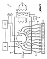
- The UV
illuminating device 1 illustrated schematically in fig. 1 is preferably mounted in ahousing 16 illustrated only schematically here, and consists of a UV lamp 2 and several, advantageously 5 to 50, preferably 10 to 30optical fibres 3, which surround the UV lamp 2 and are each fixed by a holder 4. The UV lamp 2 in question is suitably a mercury lamp, especially a doped medium pressure mercury lamp, whereby a medium pressure lamp HPA 2020 from Philips or a comparable medium pressure lamp from the company Heraeus can be used for example. Theoptical fibres 3 conveniently have a length of 0.3 to 2 m and are advantageously formed as liquid optical fibres, since these are particularly well suited to the transmission of UV light. Liquid optical fibres are notable for their high UV transmission, their more homogeneous distribution of intensity of the emerging light rays compared with quartz fibre bundles, and their higher usable cross-sectional area given the same diameter. The UV lamp 2 can be suitably mounted on a quick-change cradle (not illustrated) to enable the lamp 2 to be exchanged easily. The emission spectrum of the UV lamp 2 advantageously has a high UV intensity in the wavelength range 280 - 360 nm, since in this range various types of photoinitiators that can be used in lens material can be activated, for example Irgacure 2050. Due in particular to the radial arrangement of theoptical fibres 3 in relation to the longitudinal axis of the UV lamp 2, a high proportion of the radiation emitting from the UV lamp 2 can be coupled into theoptical fibres 3 and thus used for crosslinking. The maximum number of optical fibres that can be used is dependent on the diameter of the UV lamp 2 and the distance to the UV lamp. In addition, there is advantageously a sensor 5, which measures the intensity of UV radiation. It is located near to the UV lamp 2. The measurement is passed on to a regulatingunit 6 which compares the measured intensity of radiation with a theoretical value and regulates the current intensity I to keep it constant. In addition, a cool stream of air 7 is provided to cool the UV lamp 2. It is passed from the cold components over the hot components by means of an appropriate construction of thehousing 16, or by aventilator 22, respectively. The airstream is controlled by one or more temperature sensors 8 which measure the temperature inside the housing. The cool air stream ensures that the UV lamp 2 bums at an optimum temperature and that the components in the housing of the lamp do not become overheated. In this way, constant operating conditions are assured, which also prolong the life of the UV lamp 2. - The coupling of UV light into the
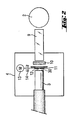
optical fibres 3 is illustrated in more detail in fig. 2. In order to couple a high intensity of radiation into the optical fibres, a minimum distance to the UV lamp is required, advantageously ca. 1 mm. Since the surface of the UV lamp reaches a temperature or more than 800°C, direct coupling to a liquid optical fibre is impossible owing to its temperature sensitivity. Therefore, the light emitting from the UV lamp is firstly coupled into aquartz rod 9, the diameter of which is co-ordinated with that of theoptical fibre 3. The length of thequartz rod 9 depends on the effectiveness of cooling produced by the stream of air. In a first approximation, the length of thequartz rod 9 has no affect on the light intensity that can be coupled into theoptical fibres 3. Depending on the design of the lamp, the length of thequartz rod 9 is advantageously between 50 and 120 mm. Between the end of thequartz rod 9 facing away from the UV lamp 2 and theadmission area 30 to the optical fibres, there is advantageously a cut-onfilter 10 which shades out the short-waved UV radiation < 280 nm, since this causes a more rapid ageing of theoptical fibres 3. The cut-on filter additionally prevents polymer degradation of the lens material. The cut-onfilter 10 is suitably a WG 305 or 295 filter from the company Schott. Furthermore, adiaphragm 11 is provided between the cut-onfilter 10 and the opticalfibre admission area 30. By adjusting theaperture 12 of thediaphragm 11, the intensity of radiation entering theoptical fibre 3 can be regulated. To regulate the coupled light intensity, the distance between the opticalfibre admission area 30 and thequartz rod 9 can also be modified. If a high UV intensity is desired, the distance should be as short as possible. In particular, there may be provisions for thediaphragm aperture 12 to be controlled via a steppingmotor unit 13 which is linked to thediaphragm 11 in particular by aflexible coupling 14, whereby adjustment of thediaphragm aperture 12 can be regulated by the measurement of light intensity using a suitableUV measuring unit 15 at the light exit. There should be provision in particular for thediaphragm 11 of eachoptical fibre 3 to be adjustable independently. As well as solving this by means of a stepping motor unit, thediaphragms 11 may also be controlled manually if desired. Theoptical fibres 3 emerge from thehousing 16 and are respectively arranged over acasting mould 17. - Fig. 3 depicts the exposure of a
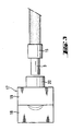
casting mould 17 consisting of alower mould half 18 and anupper mould half 19. Arranged between the end of anoptical fibre 3 and theupper mould half 19 is preferably aUV condenser 20, which consists of tempered quartz lenses. Thecondenser 20 serves to bundle the emitting ray of light. The optics thereof are co-ordinated with the geometry of the casting mould. In order to produce a contact lens which is polymerised throughout and has good quality of the edges, the distances between the end of theoptical fibre 3 and thecondenser 20 and between thecondenser 20 and theupper mould half 19 are crucial. In addition, for an optimum path of rays, a diaphragm must be provided in theupper mould half 19. If the distance between thecondenser 20 and thecasting mould 17 is increased, the intensity of radiation is reduced. This leads to slower polymerisation of the lens material. However, if there is constant exposure time and the intensity of radiation is too high, the contact lenses become brittle and the quality of the edges of the contact lenses deteriorates. When selecting the distance between thecondenser 20 and theupper mould 19, an optimum setting must be found, which also depends on the geometry of the upper mould half. This distance is suitably between 30 and 5 mm. - In this way, by coupling the UV light into the mould cavity using optical fibres, the invention enables the mould cavity to be illuminated evenly. By coupling a number of optical fibres to a UV lamp, a very high and even intensity of illumination can be attained in an efficient manner, so that it is possible to polymerise the introduced moulding material very rapidly.
Claims (14)
- UV illuminating device for crosslinking biocompatible, polymerisable material in order to produce an ophthalmic moulding, in particular a contact lens in a casting mould (17) consisting of two mould halves (18-19), characterized by one or more UV lamps (2), which are each surrounded by several optical fibres (3) whereby each optical fibre is linked to one of several casting moulds (17).
- UV illuminating device according to claim 1, whereby the UV lamp (2) is a mercury lamp.
- UV illuminating device according to claim 2, whereby the UV lamp (2) is a doped mercury lamp.
- UV illuminating device according to one or more of claims 1 to 3, whereby the optical fibres (3) are liquid optical fibres.
- UV illuminating device according to one or more of claims 1 to 4, whereby the emission spectrum of the UV lamp (2) has a high UV intensity at 280 - 360 nm.
- UV illuminating device according to one or more of claims 1 to 5, whereby a sensor (5) measuring the radiation intensity of the UV lamp (2) is provided and connected to a regulating unit (6) to regulate the UV radiation.
- UV illuminating device according to one or more of claims 1 to 6, whereby a measuring unit is provided to measure the emitting UV radiation intensity.
- UV illuminating device according to one or more of claims 1 to 7, whereby in order to couple in the UV radiation, a quartz rod (9) is respectively provided between the UV lamp (2) and the light admission area (30) of the optical fibre.
- UV illuminating device according to claim 8, whereby a cut-on filter (10) is provided between the quartz rod (9) and the optical fibre in order to absorb short-waved UV radiation.
- UV illuminating device according to one or more of claims 1 to 9, whereby a diaphragm (11) is provided between the optical fibre (3) and the UV lamp (2).
- UV illuminating device according to claim 10, whereby the aperture of the diaphragm is adjusted by means of a stepping motor unit.
- UV illumination device according to 10, whereby the aperture of the diaphragm (11) is controlled in accordance with the measurement of UV radiation intensity being emitted.
- UV illuminating device according to one or more of claims 1 to 12, whereby a UV condenser (20) is mounted between the optical fibre (3) and the upper mould half (19).
- UV illuminating device according to one or more of claims 1 to 13, whereby the optical fibres(3) are arranged radially around the UV lamp (2) in relation to the longitudinal axis of the UV lamp (2).
Priority Applications (1)
| Application Number | Priority Date | Filing Date | Title |
|---|---|---|---|
| EP00943875A EP1212188B1 (en) | 1999-06-25 | 2000-06-23 | Uv-illumination device |
Applications Claiming Priority (4)
| Application Number | Priority Date | Filing Date | Title |
|---|---|---|---|
| EP99112256 | 1999-06-25 | ||
| EP99112256 | 1999-06-25 | ||
| PCT/EP2000/005835 WO2001000393A2 (en) | 1999-06-25 | 2000-06-23 | Uv-illumination device |
| EP00943875A EP1212188B1 (en) | 1999-06-25 | 2000-06-23 | Uv-illumination device |
Publications (2)
| Publication Number | Publication Date |
|---|---|
| EP1212188A2 EP1212188A2 (en) | 2002-06-12 |
| EP1212188B1 true EP1212188B1 (en) | 2004-05-19 |
Family
ID=8238429
Family Applications (1)
| Application Number | Title | Priority Date | Filing Date |
|---|---|---|---|
| EP00943875A Expired - Lifetime EP1212188B1 (en) | 1999-06-25 | 2000-06-23 | Uv-illumination device |
Country Status (6)
| Country | Link |
|---|---|
| EP (1) | EP1212188B1 (en) |
| JP (1) | JP4717304B2 (en) |
| AT (1) | ATE267080T1 (en) |
| AU (1) | AU5819100A (en) |
| DE (1) | DE60010904T2 (en) |
| WO (1) | WO2001000393A2 (en) |
Families Citing this family (9)
| Publication number | Priority date | Publication date | Assignee | Title |
|---|---|---|---|---|
| DE3127774A1 (en) * | 1981-07-14 | 1983-02-03 | Knorr-Bremse GmbH, 8000 München | ACCELERATOR FOR CONTROL VALVES, IN PARTICULAR THREE-PRESSURE CONTROL VALVES OF RAIL VEHICLE AIR BRAKE SYSTEMS |
| WO2001074576A1 (en) * | 2000-03-31 | 2001-10-11 | Bausch & Lomb Incorporated | Method and device to control polymerization |
| EP1314527B1 (en) * | 2001-11-14 | 2009-08-26 | Novartis AG | Contact lens manufacture using UV light |
| CN100355546C (en) * | 2003-06-27 | 2007-12-19 | 中国科学院沈阳自动化研究所 | Ultraviolet optical system for fast molding |
| WO2005032791A1 (en) * | 2003-10-06 | 2005-04-14 | Menicon Co., Ltd. | Process for producing eyelens article and production apparatus therefor |
| JP4995100B2 (en) * | 2005-02-07 | 2012-08-08 | ヘンケル コーポレイション | Injection molding process, apparatus and materials for forming a cure-in-place gasket |
| US9073241B2 (en) | 2005-02-07 | 2015-07-07 | Henkel IP & Holding GmbH | Injection molding process and compositions with improved sealing characteristics for mold-in-place gaskets |
| US7785092B2 (en) * | 2005-08-09 | 2010-08-31 | Coopervision International Holding Company, Lp | Systems and methods for producing contact lenses from a polymerizable composition |
| EP1757435A1 (en) * | 2005-08-24 | 2007-02-28 | Novartis AG | Process for the manufacture of an ophthalmic lens |
Family Cites Families (15)
| Publication number | Priority date | Publication date | Assignee | Title |
|---|---|---|---|---|
| DE3245655A1 (en) * | 1982-09-01 | 1984-06-14 | Johann Josef 8918 Diessen Kerschgens | UV irradiation device, preferably as an accessory arrangement for an electric hairdrier |
| JPS59215838A (en) * | 1983-05-24 | 1984-12-05 | Mitsubishi Electric Corp | Molding apparatus |
| JPS61261009A (en) * | 1985-05-15 | 1986-11-19 | Kawasumi Lab Inc | Resin-curing process |
| JPS62132595A (en) * | 1985-12-05 | 1987-06-15 | Miyama Kogyo Kk | Heater for aeration tank |
| GB8601967D0 (en) * | 1986-01-28 | 1986-03-05 | Coopervision Optics | Manufacturing contact lenses |
| DE3737605A1 (en) * | 1987-11-05 | 1989-05-18 | Mutzhas Maximilian F | Ultraviolet fluorescent lamp without any UV-B radiation |
| JP2682017B2 (en) * | 1988-06-21 | 1997-11-26 | 株式会社ニコン | Projection exposure apparatus and exposure method |
| GB2226272B (en) * | 1988-11-02 | 1993-01-13 | Nat Res Dev | Contact lens cast moulding and packaging |
| JPH02187707A (en) * | 1989-01-14 | 1990-07-23 | Sumitomo Electric Ind Ltd | Method of molding and reinforcing fusion spliced part of optical fiber |
| DE4014363C2 (en) * | 1990-05-04 | 2000-10-26 | Guenther Nath | UV polymerizer for industrial purposes |
| IL110281A (en) * | 1993-07-19 | 1998-10-30 | Novartis Ag | Process and device for the manufacture of mouldings and mouldings manufactured in accordance with that process |
| TW272976B (en) * | 1993-08-06 | 1996-03-21 | Ciba Geigy Ag | |
| IL113904A0 (en) * | 1994-06-10 | 1995-08-31 | Johnson & Johnson Vision Prod | Mold clamping and precure of a polymerizable hydrogel |
| JP3115822B2 (en) * | 1996-06-04 | 2000-12-11 | 松下電子工業株式会社 | Ultraviolet irradiation apparatus and irradiation method |
| TW429327B (en) * | 1997-10-21 | 2001-04-11 | Novartis Ag | Single mould alignment |
-
2000
- 2000-06-23 AT AT00943875T patent/ATE267080T1/en not_active IP Right Cessation
- 2000-06-23 JP JP2001506082A patent/JP4717304B2/en not_active Expired - Lifetime
- 2000-06-23 EP EP00943875A patent/EP1212188B1/en not_active Expired - Lifetime
- 2000-06-23 DE DE60010904T patent/DE60010904T2/en not_active Expired - Lifetime
- 2000-06-23 AU AU58191/00A patent/AU5819100A/en not_active Abandoned
- 2000-06-23 WO PCT/EP2000/005835 patent/WO2001000393A2/en active IP Right Grant
Also Published As
| Publication number | Publication date |
|---|---|
| DE60010904T2 (en) | 2005-05-25 |
| ATE267080T1 (en) | 2004-06-15 |
| JP2003503234A (en) | 2003-01-28 |
| WO2001000393A2 (en) | 2001-01-04 |
| EP1212188A2 (en) | 2002-06-12 |
| AU5819100A (en) | 2001-01-31 |
| DE60010904D1 (en) | 2004-06-24 |
| WO2001000393A3 (en) | 2002-04-11 |
| JP4717304B2 (en) | 2011-07-06 |
Similar Documents
| Publication | Publication Date | Title |
|---|---|---|
| US5135686A (en) | Method and apparatus for continuous hardening of light-curing resins | |
| US5928575A (en) | Methods for eyeglass lens curing using ultraviolet light | |
| US6280171B1 (en) | El apparatus for eyeglass lens curing using ultraviolet light | |
| US6712596B1 (en) | System for producing ultraviolet blocking lenses | |
| EP1212188B1 (en) | Uv-illumination device | |
| KR100193488B1 (en) | Method and apparatus for manufacturing plastic lens | |
| WO1997039880A9 (en) | Methods and apparatus for eyeglass lens curing using ultraviolet light and improved cooling | |
| EP1197769A1 (en) | Method of manufacturing plastic optical fiber | |
| US6737661B2 (en) | Pre-treatment of molds | |
| WO2005032791A1 (en) | Process for producing eyelens article and production apparatus therefor | |
| CN101535034A (en) | High intensity UV mold pretreatment | |
| RU2000126815A (en) | METHOD FOR MANUFACTURING ARTIFICIAL EYE CRYSTALS | |
| US20060104062A1 (en) | Apparatus for the transport of light emitted by a short-arc lamp | |
| KR20180013273A (en) | UV photopolymerization system for fabricating contact lenses |
Legal Events
| Date | Code | Title | Description |
|---|---|---|---|
| PUAI | Public reference made under article 153(3) epc to a published international application that has entered the european phase |
Free format text: ORIGINAL CODE: 0009012 |
|
| 17P | Request for examination filed |
Effective date: 20011207 |
|
| AK | Designated contracting states |
Kind code of ref document: A2 Designated state(s): AT BE CH CY DE DK ES FI FR GB GR IE IT LI LU MC NL |
|
| AX | Request for extension of the european patent |
Free format text: AL;LT;LV;MK;RO;SI |
|
| 17Q | First examination report despatched |
Effective date: 20020626 |
|
| RAP1 | Party data changed (applicant data changed or rights of an application transferred) |
Owner name: NOVARTIS AG Owner name: NOVARTIS PHARMA GMBH |
|
| RAP1 | Party data changed (applicant data changed or rights of an application transferred) |
Owner name: NOVARTIS AG Owner name: NOVARTIS PHARMA GMBH |
|
| GRAP | Despatch of communication of intention to grant a patent |
Free format text: ORIGINAL CODE: EPIDOSNIGR1 |
|
| RAP1 | Party data changed (applicant data changed or rights of an application transferred) |
Owner name: NOVARTIS PHARMA GMBH Owner name: NOVARTIS AG |
|
| GRAS | Grant fee paid |
Free format text: ORIGINAL CODE: EPIDOSNIGR3 |
|
| GRAA | (expected) grant |
Free format text: ORIGINAL CODE: 0009210 |
|
| AK | Designated contracting states |
Kind code of ref document: B1 Designated state(s): AT BE CH CY DE DK ES FI FR GB GR IE IT LI LU MC NL PT SE |
|
| PG25 | Lapsed in a contracting state [announced via postgrant information from national office to epo] |
Ref country code: IT Free format text: LAPSE BECAUSE OF FAILURE TO SUBMIT A TRANSLATION OF THE DESCRIPTION OR TO PAY THE FEE WITHIN THE PRESCRIBED TIME-LIMIT;WARNING: LAPSES OF ITALIAN PATENTS WITH EFFECTIVE DATE BEFORE 2007 MAY HAVE OCCURRED AT ANY TIME BEFORE 2007. THE CORRECT EFFECTIVE DATE MAY BE DIFFERENT FROM THE ONE RECORDED. Effective date: 20040519 Ref country code: AT Free format text: LAPSE BECAUSE OF FAILURE TO SUBMIT A TRANSLATION OF THE DESCRIPTION OR TO PAY THE FEE WITHIN THE PRESCRIBED TIME-LIMIT Effective date: 20040519 Ref country code: NL Free format text: LAPSE BECAUSE OF FAILURE TO SUBMIT A TRANSLATION OF THE DESCRIPTION OR TO PAY THE FEE WITHIN THE PRESCRIBED TIME-LIMIT Effective date: 20040519 Ref country code: FI Free format text: LAPSE BECAUSE OF FAILURE TO SUBMIT A TRANSLATION OF THE DESCRIPTION OR TO PAY THE FEE WITHIN THE PRESCRIBED TIME-LIMIT Effective date: 20040519 Ref country code: LI Free format text: LAPSE BECAUSE OF FAILURE TO SUBMIT A TRANSLATION OF THE DESCRIPTION OR TO PAY THE FEE WITHIN THE PRESCRIBED TIME-LIMIT Effective date: 20040519 Ref country code: CY Free format text: LAPSE BECAUSE OF FAILURE TO SUBMIT A TRANSLATION OF THE DESCRIPTION OR TO PAY THE FEE WITHIN THE PRESCRIBED TIME-LIMIT Effective date: 20040519 Ref country code: CH Free format text: LAPSE BECAUSE OF FAILURE TO SUBMIT A TRANSLATION OF THE DESCRIPTION OR TO PAY THE FEE WITHIN THE PRESCRIBED TIME-LIMIT Effective date: 20040519 |
|
| REG | Reference to a national code |
Ref country code: GB Ref legal event code: FG4D |
|
| RIN1 | Information on inventor provided before grant (corrected) |
Inventor name: SEIFERLING, BERNHARD Inventor name: HEINRICH, AXEL Inventor name: MUELLER, ACHIM |
|
| REG | Reference to a national code |
Ref country code: CH Ref legal event code: EP |
|
| REG | Reference to a national code |
Ref country code: IE Ref legal event code: FG4D |
|
| PG25 | Lapsed in a contracting state [announced via postgrant information from national office to epo] |
Ref country code: LU Free format text: LAPSE BECAUSE OF NON-PAYMENT OF DUE FEES Effective date: 20040623 |
|
| REF | Corresponds to: |
Ref document number: 60010904 Country of ref document: DE Date of ref document: 20040624 Kind code of ref document: P |
|
| PG25 | Lapsed in a contracting state [announced via postgrant information from national office to epo] |
Ref country code: MC Free format text: LAPSE BECAUSE OF NON-PAYMENT OF DUE FEES Effective date: 20040630 Ref country code: BE Free format text: LAPSE BECAUSE OF NON-PAYMENT OF DUE FEES Effective date: 20040630 |
|
| PG25 | Lapsed in a contracting state [announced via postgrant information from national office to epo] |
Ref country code: SE Free format text: LAPSE BECAUSE OF FAILURE TO SUBMIT A TRANSLATION OF THE DESCRIPTION OR TO PAY THE FEE WITHIN THE PRESCRIBED TIME-LIMIT Effective date: 20040819 Ref country code: DK Free format text: LAPSE BECAUSE OF FAILURE TO SUBMIT A TRANSLATION OF THE DESCRIPTION OR TO PAY THE FEE WITHIN THE PRESCRIBED TIME-LIMIT Effective date: 20040819 Ref country code: GR Free format text: LAPSE BECAUSE OF FAILURE TO SUBMIT A TRANSLATION OF THE DESCRIPTION OR TO PAY THE FEE WITHIN THE PRESCRIBED TIME-LIMIT Effective date: 20040819 |
|
| PG25 | Lapsed in a contracting state [announced via postgrant information from national office to epo] |
Ref country code: ES Free format text: LAPSE BECAUSE OF FAILURE TO SUBMIT A TRANSLATION OF THE DESCRIPTION OR TO PAY THE FEE WITHIN THE PRESCRIBED TIME-LIMIT Effective date: 20040830 |
|
| LTIE | Lt: invalidation of european patent or patent extension |
Effective date: 20040519 |
|
| NLV1 | Nl: lapsed or annulled due to failure to fulfill the requirements of art. 29p and 29m of the patents act | ||
| REG | Reference to a national code |
Ref country code: CH Ref legal event code: PL |
|
| BERE | Be: lapsed |
Owner name: *NOVARTIS A.G. Effective date: 20040630 |
|
| ET | Fr: translation filed | ||
| PLBE | No opposition filed within time limit |
Free format text: ORIGINAL CODE: 0009261 |
|
| STAA | Information on the status of an ep patent application or granted ep patent |
Free format text: STATUS: NO OPPOSITION FILED WITHIN TIME LIMIT |
|
| 26N | No opposition filed |
Effective date: 20050222 |
|
| PG25 | Lapsed in a contracting state [announced via postgrant information from national office to epo] |
Ref country code: PT Free format text: LAPSE BECAUSE OF NON-PAYMENT OF DUE FEES Effective date: 20041019 |
|
| REG | Reference to a national code |
Ref country code: FR Ref legal event code: PLFP Year of fee payment: 17 |
|
| REG | Reference to a national code |
Ref country code: FR Ref legal event code: PLFP Year of fee payment: 18 |
|
| REG | Reference to a national code |
Ref country code: FR Ref legal event code: PLFP Year of fee payment: 19 |
|
| PGFP | Annual fee paid to national office [announced via postgrant information from national office to epo] |
Ref country code: DE Payment date: 20190612 Year of fee payment: 20 Ref country code: IE Payment date: 20190610 Year of fee payment: 20 |
|
| PGFP | Annual fee paid to national office [announced via postgrant information from national office to epo] |
Ref country code: FR Payment date: 20190604 Year of fee payment: 20 |
|
| PGFP | Annual fee paid to national office [announced via postgrant information from national office to epo] |
Ref country code: GB Payment date: 20190619 Year of fee payment: 20 |
|
| REG | Reference to a national code |
Ref country code: DE Ref legal event code: R082 Ref document number: 60010904 Country of ref document: DE Representative=s name: MAIWALD PATENTANWALTS- UND RECHTSANWALTSGESELL, DE Ref country code: DE Ref legal event code: R081 Ref document number: 60010904 Country of ref document: DE Owner name: ALCON INC., CH Free format text: FORMER OWNER: NOVARTIS AG, 4056 BASEL, CH |
|
| REG | Reference to a national code |
Ref country code: GB Ref legal event code: 732E Free format text: REGISTERED BETWEEN 20200123 AND 20200129 |
|
| REG | Reference to a national code |
Ref country code: DE Ref legal event code: R071 Ref document number: 60010904 Country of ref document: DE |
|
| REG | Reference to a national code |
Ref country code: GB Ref legal event code: PE20 Expiry date: 20200622 |
|
| REG | Reference to a national code |
Ref country code: IE Ref legal event code: MK9A |
|
| PG25 | Lapsed in a contracting state [announced via postgrant information from national office to epo] |
Ref country code: GB Free format text: LAPSE BECAUSE OF EXPIRATION OF PROTECTION Effective date: 20200622 |
|
| PG25 | Lapsed in a contracting state [announced via postgrant information from national office to epo] |
Ref country code: IE Free format text: LAPSE BECAUSE OF EXPIRATION OF PROTECTION Effective date: 20200623 |