EP1211583A2 - Method and device for working planning - Google Patents
Method and device for working planning Download PDFInfo
- Publication number
- EP1211583A2 EP1211583A2 EP01126892A EP01126892A EP1211583A2 EP 1211583 A2 EP1211583 A2 EP 1211583A2 EP 01126892 A EP01126892 A EP 01126892A EP 01126892 A EP01126892 A EP 01126892A EP 1211583 A2 EP1211583 A2 EP 1211583A2
- Authority
- EP
- European Patent Office
- Prior art keywords
- working
- area
- point
- areas
- planning
- Prior art date
- Legal status (The legal status is an assumption and is not a legal conclusion. Google has not performed a legal analysis and makes no representation as to the accuracy of the status listed.)
- Withdrawn
Links
Images

























Classifications
-
- B—PERFORMING OPERATIONS; TRANSPORTING
- B23—MACHINE TOOLS; METAL-WORKING NOT OTHERWISE PROVIDED FOR
- B23K—SOLDERING OR UNSOLDERING; WELDING; CLADDING OR PLATING BY SOLDERING OR WELDING; CUTTING BY APPLYING HEAT LOCALLY, e.g. FLAME CUTTING; WORKING BY LASER BEAM
- B23K26/00—Working by laser beam, e.g. welding, cutting or boring
- B23K26/02—Positioning or observing the workpiece, e.g. with respect to the point of impact; Aligning, aiming or focusing the laser beam
- B23K26/06—Shaping the laser beam, e.g. by masks or multi-focusing
- B23K26/067—Dividing the beam into multiple beams, e.g. multi-focusing
- B23K26/0673—Dividing the beam into multiple beams, e.g. multi-focusing into independently operating sub-beams, e.g. beam multiplexing to provide laser beams for several stations
-
- B—PERFORMING OPERATIONS; TRANSPORTING
- B23—MACHINE TOOLS; METAL-WORKING NOT OTHERWISE PROVIDED FOR
- B23K—SOLDERING OR UNSOLDERING; WELDING; CLADDING OR PLATING BY SOLDERING OR WELDING; CUTTING BY APPLYING HEAT LOCALLY, e.g. FLAME CUTTING; WORKING BY LASER BEAM
- B23K26/00—Working by laser beam, e.g. welding, cutting or boring
- B23K26/02—Positioning or observing the workpiece, e.g. with respect to the point of impact; Aligning, aiming or focusing the laser beam
- B23K26/06—Shaping the laser beam, e.g. by masks or multi-focusing
- B23K26/067—Dividing the beam into multiple beams, e.g. multi-focusing
-
- B—PERFORMING OPERATIONS; TRANSPORTING
- B23—MACHINE TOOLS; METAL-WORKING NOT OTHERWISE PROVIDED FOR
- B23K—SOLDERING OR UNSOLDERING; WELDING; CLADDING OR PLATING BY SOLDERING OR WELDING; CUTTING BY APPLYING HEAT LOCALLY, e.g. FLAME CUTTING; WORKING BY LASER BEAM
- B23K26/00—Working by laser beam, e.g. welding, cutting or boring
- B23K26/36—Removing material
- B23K26/38—Removing material by boring or cutting
- B23K26/382—Removing material by boring or cutting by boring
-
- G—PHYSICS
- G05—CONTROLLING; REGULATING
- G05B—CONTROL OR REGULATING SYSTEMS IN GENERAL; FUNCTIONAL ELEMENTS OF SUCH SYSTEMS; MONITORING OR TESTING ARRANGEMENTS FOR SUCH SYSTEMS OR ELEMENTS
- G05B19/00—Program-control systems
- G05B19/02—Program-control systems electric
- G05B19/18—Numerical control [NC], i.e. automatically operating machines, in particular machine tools, e.g. in a manufacturing environment, so as to execute positioning, movement or co-ordinated operations by means of program data in numerical form
- G05B19/4093—Numerical control [NC], i.e. automatically operating machines, in particular machine tools, e.g. in a manufacturing environment, so as to execute positioning, movement or co-ordinated operations by means of program data in numerical form characterised by part programming, e.g. entry of geometrical information as taken from a technical drawing, combining this with machining and material information to obtain control information, named part program, for the NC machine
-
- G—PHYSICS
- G05—CONTROLLING; REGULATING
- G05B—CONTROL OR REGULATING SYSTEMS IN GENERAL; FUNCTIONAL ELEMENTS OF SUCH SYSTEMS; MONITORING OR TESTING ARRANGEMENTS FOR SUCH SYSTEMS OR ELEMENTS
- G05B2219/00—Program-control systems
- G05B2219/30—Nc systems
- G05B2219/35—Nc in input of data, input till input file format
- G05B2219/35216—Program, generate nc program, code from cad data
-
- G—PHYSICS
- G05—CONTROLLING; REGULATING
- G05B—CONTROL OR REGULATING SYSTEMS IN GENERAL; FUNCTIONAL ELEMENTS OF SUCH SYSTEMS; MONITORING OR TESTING ARRANGEMENTS FOR SUCH SYSTEMS OR ELEMENTS
- G05B2219/00—Program-control systems
- G05B2219/30—Nc systems
- G05B2219/36—Nc in input of data, input key till input tape
- G05B2219/36264—Program movement from first to second machining area
-
- G—PHYSICS
- G05—CONTROLLING; REGULATING
- G05B—CONTROL OR REGULATING SYSTEMS IN GENERAL; FUNCTIONAL ELEMENTS OF SUCH SYSTEMS; MONITORING OR TESTING ARRANGEMENTS FOR SUCH SYSTEMS OR ELEMENTS
- G05B2219/00—Program-control systems
- G05B2219/30—Nc systems
- G05B2219/36—Nc in input of data, input key till input tape
- G05B2219/36301—Optimisation of sequence of operations
-
- G—PHYSICS
- G05—CONTROLLING; REGULATING
- G05B—CONTROL OR REGULATING SYSTEMS IN GENERAL; FUNCTIONAL ELEMENTS OF SUCH SYSTEMS; MONITORING OR TESTING ARRANGEMENTS FOR SUCH SYSTEMS OR ELEMENTS
- G05B2219/00—Program-control systems
- G05B2219/30—Nc systems
- G05B2219/45—Nc applications
- G05B2219/45035—Printed circuit boards, also holes to be drilled in a plate
-
- G—PHYSICS
- G05—CONTROLLING; REGULATING
- G05B—CONTROL OR REGULATING SYSTEMS IN GENERAL; FUNCTIONAL ELEMENTS OF SUCH SYSTEMS; MONITORING OR TESTING ARRANGEMENTS FOR SUCH SYSTEMS OR ELEMENTS
- G05B2219/00—Program-control systems
- G05B2219/30—Nc systems
- G05B2219/45—Nc applications
- G05B2219/45139—Laser drilling
-
- G—PHYSICS
- G05—CONTROLLING; REGULATING
- G05B—CONTROL OR REGULATING SYSTEMS IN GENERAL; FUNCTIONAL ELEMENTS OF SUCH SYSTEMS; MONITORING OR TESTING ARRANGEMENTS FOR SUCH SYSTEMS OR ELEMENTS
- G05B2219/00—Program-control systems
- G05B2219/30—Nc systems
- G05B2219/50—Machine tool, machine tool null till machine tool work handling
- G05B2219/50008—Multiple, multi tool head, parallel machining
-
- H—ELECTRICITY
- H05—ELECTRIC TECHNIQUES NOT OTHERWISE PROVIDED FOR
- H05K—PRINTED CIRCUITS; CASINGS OR CONSTRUCTIONAL DETAILS OF ELECTRIC APPARATUS; MANUFACTURE OF ASSEMBLAGES OF ELECTRICAL COMPONENTS
- H05K3/00—Apparatus or processes for manufacturing printed circuits
- H05K3/0011—Working of insulating substrates or insulating layers
- H05K3/0017—Etching of the substrate by chemical or physical means
- H05K3/0026—Etching of the substrate by chemical or physical means by laser ablation
-
- Y—GENERAL TAGGING OF NEW TECHNOLOGICAL DEVELOPMENTS; GENERAL TAGGING OF CROSS-SECTIONAL TECHNOLOGIES SPANNING OVER SEVERAL SECTIONS OF THE IPC; TECHNICAL SUBJECTS COVERED BY FORMER USPC CROSS-REFERENCE ART COLLECTIONS [XRACs] AND DIGESTS
- Y02—TECHNOLOGIES OR APPLICATIONS FOR MITIGATION OR ADAPTATION AGAINST CLIMATE CHANGE
- Y02P—CLIMATE CHANGE MITIGATION TECHNOLOGIES IN THE PRODUCTION OR PROCESSING OF GOODS
- Y02P90/00—Enabling technologies with a potential contribution to greenhouse gas [GHG] emissions mitigation
- Y02P90/02—Total factory control, e.g. smart factories, flexible manufacturing systems [FMS] or integrated manufacturing systems [IMS]
Definitions
- the present invention relates generally to a method and device for working planning at the time of working a workpiece placed on a stage movable in multiple directions using working means capable of scanning or moving in multiple directions, and a method and device for producing working data therefor.
- the invention more particularly relates to a working planning method allowing the working time to be shortened, a working method for performing working determined by the working planning method, a computer readable recording medium recorded with a program for performing the working planning method, a working planning device achieving the working planning, a working device including the working planning device, and a method and device for producing working data therefor.
- the working planning method is preferably applied to a laser drilling machine for perforating a plurality of holes in a printed circuit board or the like by laser beam irradiation. According to the method, the distribution state of working positions such as perforation positions in a two-dimensional plane is mathematically interpreted and the operation of the machines is optimally planned.
- multi-layer printed circuit boards having multiple layers of printed circuit boards placed on one another have been provided.
- conductive layers formed in printed circuit boards layered on one another are electrically connected and therefore these boards are provided with through holes or via holes.
- a conductive film is formed in these holes in order to connect the conductive layers in the printed circuit boards.
- Such holes formed in a printed circuit board tend to have a reduced size (diameter) as small as 0.1 mm or less as recent printed circuit boards have a smaller size and a higher function.
- a pulse oscillation type laser beam is used to precisely form holes having such a small diameter.
- the laser drilling machine 10 mainly includes a laser oscillator 12, a beam splitter 14, a left galvano unit (also referred to as galvano system) 22L, a right galvano unit 22R, and an XY stage 40 (see Fig. 2).
- the laser oscillator 12 generates a pulsed laser beam.
- the beam splitter 14 guides the laser beam output 13 generated by the laser oscillator 12 into two scanning areas 8L and 8R (working areas) of a printed circuit board 6 to be worked (also referred to as workpiece) and halves the output to allow simultaneous working on the right and left sides.
- the left galvano unit 22L is used to scan the scanning area 8L in the X-axis direction (from the left to the right in Fig. 2) and in the Y-axis direction (from the front to the back in Fig. 2) with the laser beam 13L on the left side reflected by the beam splitter 14.
- the right galvano unit 22R is used to scan the right scanning area 8R in the X- and Y- directions with the right laser beam 13R passed through the beam splitter 14 and reflected upon a mirror 16.
- the XY stage 40 includes an X stage 40X for moving the printed circuit board 8 in the X-direction and a Y stage 40Y for moving the printed circuit board 8 in the Y-direction on the X stage 40X.
- the galvano units 22L and 22R include mirrors 24L and 24R, first galvano mirrors 26L and 26R, first galvano scanners 28L and 28R (also simply referred to as first scanners), second galvano mirrors 30L, 30R, and second galvano scanners 32L and 32R (also simply referred to as second scanners), and f ⁇ lenses 34L and 34R, respectively.
- the mirrors 24L and 24R are used to reflect the laser beams 13L and 13R, respectively.
- the first galvano mirrors 26L and 26R are used for scanning with the laser beams reflected by the mirror 24L and 24R, respectively for example in the Y-direction.
- the second galvano mirrors 30L and 30R direct the laser beams directed in the Y-direction by the first galvano mirrors 26L and 26R in the X-direction perpendicular to the Y-direction.
- the f ⁇ lenses 34L and 34R deflect the laser beams directed in the X- and Y-directions by the first and second galvano mirrors 26L and 26R, and 30L and 30R, respectively in the direction perpendicular to the surface of the printed circuit board 8 and let the beams out from irradiation apertures (not shown).
- the left galvano unit 22L is for example secured, while the right galvano unit 22R has a variable position in the X-direction, and the unit interval (referred to as L-axis value) A is changeable before working.
- the beam irradiation range on the board 6 is limited to rectangular ranges 8L and 8R (referred to as scanning areas) of for example 40 mm ⁇ 40 mm having both sides parallel to the X- and Y-axes and centered around the position immediately below the beam irradiation aperture whose position is completely secured during working.
- the board 6 is about as large as 500 mm ⁇ 600 mm at most for example, and typically larger than the scanning areas. Therefore, in order to perform perforation working over the entire board, the XY stage 40 supporting the board is driven in a desired direction in an XY plane to move the board 6.
- the laser drilling machine as described above generally operates as follows as shown in Fig. 3.
- a laser beam is irradiated upon the completion of the moving scanning (also referred to as beam scanning) from the perforation completed point on the board to the next intended perforation point using the first and second scanners 28L, 28R, 32L and 32R in the left and right units 22L and 22R, and the step is repeated.
- the perforation conditions such as perforation positions, alignment mark positions for board position registration, and the number of laser irradiation (referred to as shot number) are produced by a CAD system which is not shown and stored in data files.
- the kind of the board is mostly a packaged board such as a board for mobile phone and a mother board and therefore the arrangement of hole coordinates often has several arranged groups (patterns) of some points.
- the CAD data 50 is produced by arranging hole coordinates between the start and end signals of a pattern and writing shift amounts for the patterns as many as the number of patterns rather than arranging all the hole position data.
- a person in charge of working selects a data file in the CAD data 50 on a flexible disc or a network for the input position under the name of working data file using the input window 52 on the PC.
- Other selective inputs are performed.
- the selective inputs include information on several items such as whether or not point data is subjected to XY transformation (transformation of the X-coordinate and Y-coordinate of the point data to change the dividing line for the processing regions of the galvano units from the vertical direction to the X-axis to the vertical direction to Y-axis), the position of the right unit 22R (L-axis value), the format of the CAD data 50 (such as Excellon, SHI, and HZ formats).
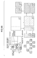
- a planning device 60 After all the items are input, and the person in charge presses an input end button (a switch button mainly for input), a planning device 60 performs planning based on the input items, and returns an planning end signal. Then, a plan view is produced and displayed on a PC screen. In the plan view, the perforation positions, processings to be separately performed by the left and right units, placement of scanning areas and the like are visibly expressed. The operator checks the plan view and presses the working start button on the window if there is no problem in the view.
- the operation allows the laser drilling machine 10 to start operating.
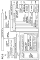
- the data planned and produced by the planning device 60 includes five kinds of data, i.e., unit interval data A, stage stop position (scanning area position) data B, visiting order data C for the stage stop positions, perforation position data D in each scanning area, and visiting order data E for the perforation positions in each scanning area.
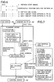
- the planning device 60 conduct setting by a method as shown in Fig. 7, using the CAD data 50 and the window input values.
- the data planned and produced by the planning device 60 will be now described.
- the interval between the left and right galvano units 22L and 22R (unit interval) A can be set about in the range, for example, from 150 to 300 mm. According to the input window 52 in the PC, the interval is set. The data is used as an instruction value when the right unit 20R is driven.
- the operation regions of the units are divided into a regular square lattice at a lattice point interval of 40 mm.
- An entire rectangular area of 40 mm ⁇ 40 mm surrounded by four lattice points is set as a scanning area.
- stage path the trajectory of the stage visiting the scanning areas
- stage path can take a zigzag path with the line advancing in the X-direction.
- All the perforation positions are labeled for example to specify an area to which each position belongs.
- the scanning areas are each for example in the shape of a regular square of 40 mm ⁇ 40 mm.
- the regular square region is for example equally divided into ten parts with respect to the X-axis, and then lines parallel to the Y-axis are drawn from the left end of the area at intervals of 4 mm.
- ten strip-like regions of 40 mm in the X-direction and 4 mm in the Y-direction are formed.
- the perforation positions of the strip-like regions are sorted with the Y coordinate values. Note however that among adjacent strip regions, one is always in the ascending order and the other in the descending order.
- the point visited next to the final point in a strip-like region is the initial point of an adjacent strip-shaped region in the right.
- the trajectory of the beam irradiation positions (referred to as galvano path) passing through the perforation positions in the scanning area determined by the above operation can generally take a zigzag path with the line advancing in the X-direction.
- the devices of the laser drilling machine operate in response to an instruction from the control device 62.
- the right unit 22R is driven in the timing in which the control device 62 receives a working start signal. Once the movement ends, a movement end signal is transmitted to the control device 62.
- the laser oscillator 12 lasses in the timing in which the control device 62 receives both movement end signals output from the units 22L and 22R and two scanners 32L and 32R. After a necessary shot number, the lasing end signal is returned to the control device 62. At the point visited last in the area, a signal indicating the end of the laser perforation working at all the perforation positions in the scanning area is returned to the control device 62. If the point is the point visited last in the scanning area and the scanning area is the scanning area visited last, a working end signal is transmitted to the window 52 on the PC.
- the scanners 28L, 28R, 32L, and 32R are driven in the timing in which the control device 62 transmits the lasing end signal output from the laser oscillator 12 or a movement end signal output from the XY stage 40. When the movement to the next perforation position is complete, the movement end signal is returned to the control device 62.
- the XY stage 40 is driven in the timing in which the control device 62 receives a signal output from the scanners 28L, 28R, 32L and 32R indicating the end of the perforation working at all the perforation positions in a scanning area. When the movement to the next scanning area is complete, the movement end signal is returned to the control device 62.
- planning is adapted to fill a previously produced form regardless of the distribution of perforation positions, which cannot be always optimal, and a device capable of optimal setting for the following four aspects has been in demand.
- one movement could wastefully cover the end-to-end distance of a scanning area, in other words, 40 mm.
- Programs in the working planning as described above are normally incorporated in software used by the laser beam machine, but the calculation load is large and could adversely affect the operation of the working machine which cannot afford a high speed processing machine for calculation. Meanwhile, in order to use up-to-date programs, they must always be upgraded. This applies to the case of extracting a program for working planning and providing a single kind of software.
- the working position data could be mailed from the user using a recording medium such as a flexible disc, and a working plan can be produced based on the data by the manufacturer's support center and sent back by mail. The exchange by mail however takes too long.
- the present invention is directed to a solution to the conventional disadvantages described above. It is a first object of the present invention to improve the throughput of a working machine without changing the responsiveness by a laser oscillator, a laser scanning mechanism, a workpiece moving mechanism and the like. According to the invention, two objectives of shortening the total time for moving a workpiece, and shortening the total scanning time by working means such as a laser beam are solved by mathematically interpreting the distribution state of working positions in a two-dimensional plane, and planning an optimum path.
- a second object of the invention is to shorten the computation time required for planning without lowering the precision of planning directed to shortening the working time by introducing a data structure to efficiently store geometrical point data.
- a third object of the invention is to provide a working planning device to carry out the working planning.
- a fourth object of the invention is to provide the capability of quickly producing working data always in the up-to-date version using a high speed processing machine dedicated for computing.
- the first object is achieved in allocating a plurality of working positions scattered on a workpiece to a plurality of working areas to be simultaneously worked, by determining an optimal working path for the working positions in each working area, and subsequently determining order of working in the working positions in each working area so that a total working time is minimized in the working areas to be simultaneously worked.
- the first object is achieved in determining order of working in a plurality of working areas scattered on a workpiece, by shifting an start point of a working path in each of the plurality of simultaneous working areas so that time for scanning or moving simultaneously performed can be equal, thereby shortening a total working time.
- the first object is achieved, in determining order of working by applying a traveling salesman problem to a plurality of working positions scattered on a workpiece or working areas set in a workpiece, by solving the traveling salesman problem, thereby minimizing a tour length, and subsequently eventually detecting a longest movement, and determining start and end points so that the longest movement is removed.
- the first object is also achieved, in determining order of working by applying a traveling salesman problem to a plurality of working positions scattered on a workpiece or working areas set in a workpiece, by solving a traveling salesman problem varied to minimize a value produced by removing a longest movement from a tour, thereby obtaining a tour, and eventually removing the longest movement to determining start and end points.
- the first object is also achieved, in determining placement of working areas to be worked by working means based on working positions scattered on a workpiece, by provisionally setting a next working area so as to enclose an end point in a first direction not yet enclosed by the working area, moving the provisionally set working area in a second direction different from the first direction to enclose an end point in the second direction, again moving the moved working area in the first direction so as to enclose the end point in the first direction in the position after the movement, and moving the re-moved working area again in the second direction so as to enclose the end point in the second direction in a position after the re-movement.
- the steps of moving are repeated to define the next working area.
- the working area has a square frame orthogonal to the first and second directions.
- the first and second directions are set to correspond to the moving direction of a workpiece.
- the first object is achieved in determining placement of working areas to be worked by working means based on working positions scattered on a workpiece, by simply dividing an entire surface of the workpiece into the working areas, and subsequently removing all the working areas without any working position.
- the first object is achieved, in determining placement of working areas to be worked by working means based on working positions scattered on a workpiece, by repeating the step of placing a working area in a position with a largest number of working positions not yet enclosed until all the working positions are enclosed.
- the first object is achieved, in determining placement of working areas to be worked by working means based on working positions scattered on a workpiece, by provisionally determining area placement, and subsequently shifting a working area to a neighborhood and removing an unnecessary working area.
- the working area may be shifted to a neighborhood and an unnecessary neighboring area is removed, provided that a point independently belonging to the working area stays within the area.
- At least two areas joined at an overlapping location may be each shifted to a neighborhood and an unnecessary neighboring area is removed, provided that a point independently belonging to the at least two areas stays within the working areas.
- the present invention in determining placement of working areas to be worked by working means based on working positions scattered on a workpiece, by determining areas to be worked so that the number of working positions belonging to each of a plurality of simultaneous working areas is equal when the same working position belongs to the plurality of areas.
- Some of the working positions belonging to the plurality of areas may be allocated to an area having a greater difference among a plurality of simultaneous working areas, some of the remaining working positions are allocated to an area having a smaller difference, and the eventually remaining working positions are distributed equally among both areas.
- the first object is solved, in determining placement of working areas to be worked by working means based on working positions scattered on a workpiece, by adjusting an area position so that working positions are gathered around the center of each working area.
- the area position may be adjusted so that the center of an extent of the working positions matches the center of the working area.
- the area position may be set as near as the center of gravity of the working positions, provided that the working positions are within the working area.
- the first object is achieved, in working a workpiece placed on a stage which is movable in a plurality of directions, by determining a moving path for the stage by solving a traveling salesman problem with fixed edge points in which a position to load the workpiece to the stage from a loader is set as a start point of the moving path for the stage, a position before transferring the workpiece to an unloaded is set as an end point.
- the first object is achieved, in working a workpiece placed on a movable stage by a plurality of working units capable of scanning or moving working means within a working area, by determining an interval between the working units so that the number of scanning or moving the working means (such as the number of beam scanning and the number of moving the drill) or the number of moving the stage is minimized.
- the units are for example a beam irradiation unit capable of scanning with a laser beam in a scanning area and a drill moving unit capable of moving a mechanical drill in a moving area.
- the number of scanning or moving the working means and the number of moving the stage may be weighted depending on difference in scanning or moving time.
- the interval of the working units may be set, and the scanning or moving ranges of the working units at the time may be overlapped, thereby obtaining area placement to minimize the number of working areas, and the number of scanning or moving of the working means and the number of moving the stage at the time may be calculated.
- the first object is achieved, by performing the above-described process in a different workpiece direction, and automatically employing the workpiece direction to minimize the number of scanning or moving the working means or the number of moving the stage.
- the second object described above is achieved, in working a workpiece using working means capable of scanning or moving in a plurality of directions, by expressing point position data representing working positions or working areas scattered on the workpiece in a tree type data structure.
- the above-described tree may be a k-dimensional binary search tree.
- the tree may be used to list point data in each working area.
- whether or not to search a child node of a node may be determined based on the degree of overlapping between a region corresponded to the child node of the node and a search region, and only when a leaf node is reached, the point data may be directly accessed.
- the nearest neighbor point to a point of interest may be searched.
- the process of searching the nearest neighbor point may be started from the root node of the tree.
- the node When a circle centered on the point of interest and having a radius as long as the distance to the present nearest neighbor point overlaps a region corresponded to a node, the node may be searched.
- node is a leaf node
- distances to all the points corresponded to the node in the region are obtained, and it may be determined whether each distance is short.
- Each point data piece may have information related to a leaf node to which the data piece belongs, the process of searching the nearest neighbor point may be performed by directly accessing the leaf node having the point of interest whose nearest neighborhood is searched, and then the search may be performed in a direction toward the root node of the tree, provided that there is a node to be searched.
- a brother node thereof or a brother node of a parent node thereof may be searched depending on a degree of how much outside they are.
- the process of searching the nearest neighbor point and the process of searching the next nearest neighbor point, using a tree removed of a found nearest neighbor point may be repeated, so that neighbor points are listed in order of their nearness to the point of interest.
- the process of searching the nearest neighbor point not yet connected to a working path by the process of searching the nearest neighbor point and connecting a new found point of interest to the working path, and the process of searching the next nearest neighbor point using a tree removed of the found point of interest and connecting a new found point of interest to the working path may be repeated from a start point to an end point to produce the working path.
- the process of removing a found point from the tree may be performed by reducing ending number of an index attached to each point data or by increasing starting number.
- the node may be attached with information indicating that it is not necessary to visit the node.
- a working path determined by the working planning method according to any one of the above working planning methods may be set as an initial solution in determining order of working by applying a traveling salesman problem.
- the second object is achieved by removing an unnecessary, high load operation by finding a set of areas in which the placement of point data in one of the working areas and the placement of point data in another working area are relatively matched.
- the process of searching a set of areas having relatively matched point data placements may be performed by producing point position data by adding a prescribed coordinate shift to all the points in one area, visiting one node after another representing a region having the point position data from the root node of a tree in the other area, and checking whether or not point position data matched with the point position data is present only when a leaf node is reached.
- the tree may be built both for the provisional working area and provisional point position data in each working area.
- the tree may be built both for the working area and point position data in each working area when the working area is defined.
- a working method performing working (such as laser machining and drilling)determined by any one of the above-described working planning methods is provided.
- the third object is achieved by a working planning device for allocating a plurality of working positions scattered on a workpiece to a plurality of working areas to be simultaneously worked.
- the device includes working path determining means for determining an optimal working path for working positions in each working area, and working order determining means for determining order of working in the working positions in each working area so that the total working time in the working areas to be simultaneously worked is minimized.
- the third object is achieved by a working planning device for planning working in determining order of working in a plurality of working areas scattered on a workpiece.
- the device includes working order shift means for shifting a start point of a working path for each of the plurality of simultaneous working areas so that the time for scanning and moving performed simultaneously can be equal among the simultaneous working areas, and shortening the total working time.
- the third object is achieved by a working planning device for planning working in determining order of working by applying a traveling salesman problem to a plurality of working positions scattered on a workpiece or working areas set in the workpiece.
- the unit includes scanning path determining means for detecting a longest movement after minimizing a round path by solving the traveling salesman problem, and determining start and end points so that the longest movement is removed.
- the third object is achieved by a working planning device for planning working in determining order of working by applying a traveling salesman problem to a plurality of working positions scattered on a workpiece or working areas set in the workpiece.
- the device includes scanning path determining means for solving a traveling salesman problem improved to minimize a value produced by removing a longest movement from a round path, thereby obtaining a round path, and eventually removing the longest movement to determine start and end points.
- the third object is achieved by a working planning device for planning working in determining placement of working areas to be worked by working means based on working positions scattered on a workpiece.
- the device includes area placement determining means for repeating a process for defining the next working area.
- the process includes provisionally setting the next working area so as to enclose an end point in a first direction not yet enclosed by a working area, moving the provisionally set working area in a second direction different from the first direction so that the area encloses an end point in the second direction, again moving the moved working area in the first direction so that the moved working area encloses the end point in the first direction, and again moving the moved working area to enclose the end point in the second direction in a position after the movement.
- the third object is achieved by a working planning device for planning working in determining placement of working areas to be worked by working means based on working positions scattered on a workpiece.
- the device includes area placement determining means for simply dividing an entire surface of the workpiece into working areas, and removing all working areas having no working position.
- the third object is achieved by a working planning device for planning working in determining placement of working areas to be worked by working means based on working positions scattered on a workpiece.
- the device includes area placement determining means for repeating a process of placing a working area in a position having the largest number of working positions not yet enclosed until all the working positions are enclosed.
- the third object is achieved by a working planning device for planning working in determining placement of working areas to be worked by working means based on working positions scattered on a workpiece.
- the device includes area placement determining means for provisionally determining area placement, shifting a working area to a neighborhood, and removing an unnecessary working area.
- the third object is achieved by a working planning device for planning working in determining placement of working areas to be worked by working means based on working positions scattered on a workpiece.
- the unit includes belonging area determining means for determining scanning areas to be worked. When the same working positions belong to a plurality of working areas, the means determines the scanning areas so that the number of working positions belonging to each of the plurality of simultaneous working areas is equal.
- the third object is achieved by a working planning device for working planning in determining placement of working areas to be worked by working means based on working positions scattered on a workpiece.
- the device includes area position adjusting means for adjusting area positions so that working positions are gathered around the center of each working area.
- the third object is achieved by a working planning device for planning working in working a workpiece placed on a stage movable in a plurality of directions.
- the device includes moving path determining means for determining a moving path for the stage by solving a traveling salesman problem with fixed edge points in which a position to load the workpiece to the stage from a loader is set as a start point of the moving path for the stage, a position before transferring the workplace to an unloaded is set as an end point.
- the third object is achieved by a working planning device for planning working in working a workpiece placed on a movable stage simultaneously using a plurality of working units capable of scanning working means in a working area.
- the device includes unit interval determining means for determining an interval of the working units so that the number of scanning or moving the working means or the number of moving the stage is minimized.
- the third object is achieved by workpiece direction determining means for performing the processing by the unit interval determining means in a different workpiece direction, and automatically employing a workpiece direction allowing the number of scanning or moving the working means or the number of moving the stage to be minimized.
- the third object is achieved by a working planning device for planning working in working a workpiece using working means capable of scanning or moving in a plurality of directions.
- the device includes means for storing point position data expressed in a tree type data structure on points representing working positions or working areas scattered on the workpiece and means for determining working area positions and order of working using the position data expressed in the tree type data structure.
- a working device includes any one of the above-described working planning devices is provided.
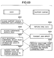
- the above-described fourth object is achieved by determining a working plan based on working position data received from a working device side through a communication line, and returning the plan to the working device side.
- the working plan may be determined by any one of the above-described methods.
- the fourth object is achieved by a working data producing device.
- the device includes means for receiving working position data from a working device side through a communication line, planning means for determining a working plan based on the received working position data, and transmission means for transmitting the determined working plan back to the working device side.
- the working plan may be determined according to any one of the above-described methods.
- a computer readable recording medium recorded with the above-described computer program is provided.
- the working position information is mathematically interpreted and the operation of the devices is planned in the optimal manner, so that the time for laser working can be reduced.
- the computation time required for planning working can be shortened without lowering the precision of the plan directed to shortening of the working time.
- the processing at higher speed according to the present invention are used at the time of determining each area in a provisional region in a later described orthogonal range query and therefore the number of use may substantially be "number of producing provisional regions ⁇ area number average", for example.
- a later described neighbor-list is produced as a preparation for a traveling salesman problem and used once for each of all the point data and area position data, and therefore the number of use may substantially correspond to "number of perforation positions + number of areas in half region.”
- a later described nearest neighbor method is used once for each traveling salesman problem, and therefore the number of use is at most "1 + number of areas in entire substrate.” ("1" is a traveling salesman problem when a stage pass is planned.)
- the number of comparison between the areas in a later described exact match query is at most about "(area number in entire board) 2 /2.” (It might appear that the amount of calculation is large with a square term, but in the exact match query in hole placement between areas, if there is even one point not in exact match, the determination is over. Therefore, the amount of calculation is generally not significant.)
- the flow process to produce a neighbor-list and solve a traveling salesman problem occupies a larger percentage in all the computation, and therefore the processing speed is significantly increased.
- the number of producing a tree is "number of producing provisional regions + 1 + area number in entire board," which is sufficiently less than the number of processing to have an increase speed by producing a tree, and time for producing a tree is not so long and is insignificant. Accordingly, the overall computation time is sufficiently shortened.
- a working plan is determined based on working position data received from the side of a working device through a communication line, and the plan is returned to the working device side, working data can quickly be produced always in the up-to-date version using a high speed processing machine dedicated for computation.
- a working planning device 70 for a laser drilling machine includes an area placement planning device 72 for a multiple-unit (two units in the present embodiment) and a stage/galvano path planning device 76.
- the two-unit area placement planning device 72 determines the operation regions of left and right galvano unites 22L and 22R based on the coordinate values of perforation points so that the number of scanning areas (working areas) is minimized, executes X-Y coordinate transformation if necessary, and determines the unit interval A to produce scanning area position data B and perforation position data D in each scanning area.
- the two-unit area placement planning device 72 incorporates an area placement planning device 74 to enclose all the points in the two-dimensional region with a minimum number of equal size rectangles and determine placement of the rectangles. The loop process is repeated until the optimal unit interval is determined.
- the area placement planning device 74 plans such area placement that the minimum number of scanning areas is obtained for an area and perforation positions in the area.
- the input of the stage/galvano path planning device 76 is the scanning area position data B and the perforation position data D, the order of visiting the scanning areas (stage path) and the order of visiting the perforation positions in each of the areas (galvano path) are planned, and scanning area position visiting order data C and perforation position visiting order data E are produced.
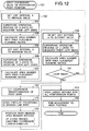
- the two-unit area placement planning device 72 performs what is called "minimization of a one-variable function" as shown in Fig. 12.
- the golden section search generally known as a minimalizing algorithm for a one-variable function is used. More specifically, when the unit interval A is input to the area placement planning device 74, the stage movement number and "the beam scanning number" or parameters (which will be detailed later) produced by weighting these values can be calculated, and the results of calculation can be regarded as the output values of a function. This is utilized to determine the unit interval which minimizes the output values.
- the meaning of the term "the beam scanning number”, the reason for minimizing the number of stage movement and "the beam scanning number” and the method of using the area placement planning device 74 incorporated in the two-unit area placement planning device 72 will be described.
- the larger number is selected and one is subtracted from the larger number to produce a beam scanning number in the certain simultaneous working areas.
- the sum of the beam scanning numbers obtained for all the simultaneous working areas is referred to as "the beam scanning number.”
- the area placements in the left and right beam irradiation regions at the time point of the determination are in full coincidence when one is horizontally shifted to the other by the unit interval, because the unit interval is constant during working.
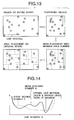
- the unit interval A is set to a value, as shown in Fig. 13, the left ends, for example, of the left and right areas are superimposed, and a temporary region is produced.
- the placement of the minimum scanning areas is determined using the area placement planning device 74 and the beam scanning number and the stage moving number for the placement can be calculated.
- the use of the area placement planning device 74 as described above allows the stage moving number and the beam scanning number to be produced for an arbitrary unit interval as shown in Fig. 14. More specifically, the object is basically achieved if the unit interval allowing these values to be minimized is for example obtained by the iteration process of several steps according to the method of making a one-variable function minimum such as golden section search.
- the golden section search is "minimalizing" algorithm (an algorithm to discover a local optimum) for a one-variable function rather than a “minimizing” algorithm (an algorithm to discover the global algorithm). Since it is very difficult to obtain the minimum value for a multimodal function in reality, the golden section search which allows the minimal value to be discovered by several steps is employed. In order to obtain a minimal value closer to the minimum value, a heuristic solution such as simulated annealing method may be applied.
- multi-purpose optimization problem (here with two purposes)
- the average beam scanning time is about in the range from 1 to 3 msec
- the average stage moving time is about in the range from 0.2 to 0.4 sec
- ⁇ is obtained from experiments. This is sometimes referred to as a "weighting parameter method.”
- the two-purpose optimization problem can also be reduced to a one-purpose optimization problem.
- the beam scanning number G can be multiplied by a coefficient ⁇ as follows: ⁇ G+ ⁇ S
- the G+ ⁇ S as a whole may be multiplied by a suitable integer (times ⁇ ) as follows: ⁇ G+ ⁇ S wherein ⁇ could be considered as being substituted by ⁇ .
- the coordinates of perforation positions are input in step 101.
- the area placement planning device 74 calculates the scanning area number and the beam scanning number at the minimum value for the unit interval (about 100 mm) and the maximum value for the unit interval (about 300 mm) or parameters produced by weighting these numbers.
- the unit interval A is at least 100 mm and at most 300 mm as is the conventional case.
- the optimal unit interval is clearly at a position near the position of width ⁇ 1/2, while it could be smaller than 100 mm or larger than 300 mm depending on the kind of board.
- the lower limit, 100 mm might not be changeable because of the physical width of the unit, while the upper limit of 300 mm may be variable.
- the minimum and maximum values, 100 mm and 300 mm are set at the initial position in the process described above (steps 102 and 105), while the area minimum position could not be included in the range or any interval in the vicinity of 100 mm might be apparently too short and might not be worth checking depending on the size of the board.
- the initial position can be set in a flexible manner depending on the size of the board.
- step 108 the unit interval A is set again at an appropriate position (based on the golden section ratio for example) between the immediate two previous positions, and the scanning area number in the position is calculated by the area placement planning device 74 in steps 109 and 110.
- step 110 in Fig. 12 if the calculation result of ⁇ G+ ⁇ S is judged to be minimum, the loop ends in the step 111, and if it is not minimum, the loop returns to the step 108.
- the process exits the loop in the step 111 the area number and the unit interval at the time are stored, and the point data is subjected to X-Y coordinate transformation in step 112, and the loop process from the steps 102 to 111 enclosed by the broken line is executed again.
- the X-Y coordinate transformation of data allows the X- and Y- axes of the original data to be vertically sectioned
- the unit interval A can be optimized for both and the more suitable interval is selected so that the beam scanning number and the stage moving number are less.
- calculation can be executed for sectioning both in the X- and Y- directions and the optimal one among the results can be selected as shown in Fig. 16.
- the operator must be notified of the shift.
- step 114 in Fig. 12 the unit interval with the minimum stage moving number and the minimum beam scanning number is defined. If the X-axis of the original CAD data is sectioned, X-Y coordinate transformation is once again performed for returning to the original.
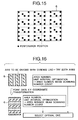
- the process proceeds to step 115, and it is determined in which scanning area perforation positions in the overlapped part are included in. More specifically, the labels (numbers) of scanning areas to which all the perforation point positions belong are defined.
- the areas F and G overlap, and there are regions W(1) and W(2) overlapping both areas F(1), F(2) and G(1) and G(2) ((1) for the left unit and (2) for the right unit).
- the number of holes in the left and right simultaneous working areas are equally distributed so as to minimize the sum of the number of holes in the area with the larger number of holes between the left and right areas F and the number of holes in the area with the larger number of holes between the left and right areas G. This process can reduce the time for processing. Min(Max(number of holes in F(1), number of holes in F(2)) + Max(number of holes in G(1), number of holes in G(2))
- the number of galvano shots is 55 in the areas F and 55 in areas G, i.e., 110 in total, which is 20 shots less than that by the conventional method.
- the order of executing overlapped part distribution process is determined for example a random order or an order from the largest overlapped number to the smallest overlapped number.
- the number of holes is expressed with small characters as f(1), and g(1).
- f(1) and f(2) are the numbers of holes belonging to positions in the areas F in the left and right units, respectively and not overlapping G
- g(1) and g(2) are the numbers of holes belonging to positions in the areas G in the left and right units, respectively and not overlapping F
- fg(1) and fg(2) are the number of holes in the overlapping parts W1 and W2 between areas F and G in the left and right units.
- are the numbers of holes belonging to the areas F(1) and G(1) in the left unit and the areas F(2) and G(2) in the right units.
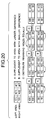
- step 201 f(1)-f(2) and g(1)-g(2) and their absolute values are calculated.
- step 202 as denoted by the arrow A in Fig. 20 showing examples of numerical values, a number of holes is taken from the overlapping part and added to the area having a greater absolute value and a smaller number of holes.
- step 203 as denoted by the arrow B in Fig. 20, a number of holes is taken from the overlapping part to the area having the smaller absolute value and a smaller number of holes.
- step 204 as denoted by the arrow C in Fig. 20, the number of holes remaining in the overlapping part is equally distributed to areas F and G, and the process is completed.
- the above steps determine how many perforation positions in the overlapping part are taken and distributed to areas F and G. Meanwhile, which perforation position is distributed to area F or G is not determined.
- the distance from the center of F is obtained for all the perforation positions in the overlapping part, and positions nearer to the center F are distributed based on the number to be distributed to F, in other words, a heuristic method is applied.
- the method of distributing the holes in the overlapping part is not limited to this, and as shown in Fig. 21, positions nearer to the center of each area may be distributed to the area.
- step 116 the center of the scanning area is fine-adjusted using the present position of point data in the original area 8, and the points are gathered in the center of the adjusted area 8', so that the working precision is improved. More specifically, as shown in Fig. 22, the fine-adjustment is made with the center of the extent of the perforation position (the average of the minimum and maximum values for each axis). Alternatively, as shown in Fig. 23, the adjustment is made so that the center of the gravity of the perforation positions is in the center of the adjusted area 8'. In the latter case, if there is a point P apart from the area, adjustment is made to the further extent to cover all the perforation positions by the area.
- the Y-axis may be shifted to the position of center of the gravity but if the X-axis is shifted to the position of the center of the gravity, a point P is out of the area, and therefore the central position is shifted to the limit position to cover all the perforation positions.
- the operation is not particularly effective in reducing time, while it is effective in improving the working precision. This is because the central part provides high precision in connection with aberration of the f ⁇ lenses 34L and 34R.
- the method can be a substitute processing according to which data is input using a window 52 on a PC and the above steps are simplified.
- Fig. 24 shows a general process of processing according to the method.
- Fig. 25 shows a candidate for the unit interval according to the method.
- the area number for each of the following cases is obtained by the area placement planning device 74.
- they are the case of determining as the unit interval "the distance from a left end in which area a point is located to a position where a dividing line of the unit is shifted from a position corresponding to half the width in which area the point is located to the point location" and the case of determining as the unit interval "the shift of a pattern all between the minimum value for the unit interval (about 100 mm) and the maximum value (about 300 mm), when CAD data includes pattern information.” Then the smallest area number among all is selected.
- the optimal unit interval is the shift amount of the maximum pattern A, i.e., 260 mm or a half (board horizontal size 560 mm/2) i.e., 280 mm.
- the area placement planning device 74 incorporated in the two-unit area placement planning device 72 determines placement of rectangular areas when a minimum number of equal size rectangles (regular square for example) enclose all the points in the two-dimensional region.
- the device allows the minimized scanning areas (and therefore the minimized stage moving number).
- the present position (X, Y) of interest is at the lower left corner vertex of an area (regular square).
- the position of the area is updated.
- step 401 the coordinates of perforation positions are input.
- step 402 the perforation positions are sorted based on the values of the X-coordinates.
- steps 406, 409, and 411 the area position is updated in the negative or positive direction on the X-axis. This is because to enclose perforation positions (1) from a perforation position with a small value on the X-axis generally, and (2) from a perforation position with a small value on the Y-axis while the X-axis and Y-axis values are updated so that in one area determination loop, areas can be prevented from overlapping as much as possible.
- the device performs two steps of updating the area position in the negative direction (downward) on the Y-axis (steps 406, 411) and the step of updating the area position in the positive direction on the X-axis (rightward) (step 409).
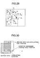
- Fig. 27 if four areas E1 to E4 are defined and the position of the fifth area E5 is searched, points whose covering areas are not defined are searched in the sorted order in step 403.
- the leftmost point P1 not enclosed is found in step 404 as shown in Fig. 28, and the area E5 enclosing the point P1 is provisionally produced in step 405.
- step 406 the lowermost point not enclosed in a band region B1 corresponding to the width of the area, more specifically, a part under the present area position E5 whose area is yet to be determined with the minimum Y-coordinate value is searched in order to update the area position downward (area position updating (1)). If no such point is found, the previous position is defined.
- the position of the area E5 is moved downward so that the point P2 is positioned on the lower side.
- the value of the Y-coordinate is updated by Y', while if the area at (X, Y') and the already defined area overlaps for an area more than a certain value as shown in Fig. 30, the point with the minimum Y-coordinate value is once again searched in the nonoverlapping region e above the greatly overlapping region. If the point is discovered in the region e (Y"), the value of the Y-coordinate is updated by Y" which is the minimum Y-coordinate value in the region e, and overlapping is prevented. If no such point is discovered in the region e, the area position to be processed next is updated rightward, so that the position should be updated rightward to avoid overlapping, and therefore the value of Y-coordinate is directly updated by Y'.
- step 407 When the value of the Y-coordinate is updated in step 407, the process proceeds to step 409, the position of the area E5 is moved rightward as shown in Fig. 31 in order to update the area position, and the value of the X-coordinate is updated by the value of a point P3 with the minimum X-coordinate value in the present area (updating of the area position (2)).
- step 409 If the value of the X-coordinate is updated in step 409, the process proceeds to step 411, and the step of again updating the area position downward is performed (updating of area (3)). More specifically, as shown in Fig. 32, the side having the maximum Y-coordinate value on the upper side among the four sides of the already determined areas is searched in the negative direction on the Y-axis from the present area positions (X, Y). Note however that areas which do not have overlapping sides in a prescribed level or more by the downward movement is ignored. The Y-coordinate of the discovered side is Y'.
- Points with the minimum Y coordinate value whose area has not be determined is searched in the rectangular region B2 which is under the lower part of the present area and whose Y-coordinate value is equal to or larger than Y'. If the point is discovered, the Y-coordinate value is updated by the value.
- first loop for determining one area
- second loop for fine adjustment of an area position rightward and downward.
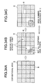
- Fig. 34 local search in combinatorial optimization problem (also referred to as "iterative improvement method) may be applied, area placement excluding areas without points may be produced based on the conventional area placement, and then the area position may be shifted up and down, and rightward and leftward, so that unnecessary areas can be removed one after another.
- Fig. 35 areas without points are excluded from the conventional areas as shown (A) in Fig. 34, so that the area placement as shown (B) in Fig. 34 is generated as an initial solution.
- solution is one of possible combinations (solution set) of "area placements (and area numbers) enclosing all the points.”
- a "good solution” refers to a solution with a small area number.
- the initial solution can be generated by various other methods than the above method.
- one possible method may be so-called greedy algorithm known for combinatorial optimization problem which repeats the process of "discovering positions enclosing the largest number of non-enclosed points and placing areas" until all the points are enclosed.
- the area placement determined by the process as shown in Fig. 26 may be an initial solution.
- step 502 y is substituted with an initial solution x, and in step 503, a neighborhood N(y) of the solution y is searched. More specifically, as shown in Fig. 36, provided that points independently belonging to an area Ei of interest stay within the area, if the area position is moved to a position in a movable region, and points independently belonging to an area Ej, one of areas neighboring the area of interest Ei are included in the area resulting from the movement, the neighbor area Ej is not necessary. Therefore, the neighbor area Ej is deleted to discover a solution z better than y, and in step 505, the value of the thus discovered solution z is submitted for y, and the step 503 is repeated.
- step 503 once a solution better than y can no longer be discovered in N(y), the process proceeds to step 506 and the value of the present y is set as a solution, and the processing ends.
- Fig. 37 provided that points independently belonging to two neighbor areas Ei and Ei+1 joined by an overlapping region, in other words points present in regions other than the overlapping region stay within the two areas, if the area positions are moved to positions in the movable region, and points belonging to a neighbor area Ej are all included in the two areas, the neighbor area Ej is not necessary and may be deleted.
- the number of areas joined by the overlapping region may by two or more. More specifically, provided that points independently belonging to n areas Ei, ...., Ei+n-1 joined by an overlapping region (n: 2 or more), in other words points present in the regions other than the overlapping region stay within the n areas, if the n areas are moved to positions in the movable range of the area, and all the points independently belonging to one neighbor area Ej are included in the n areas, the neighbor area Ej is not necessary and may be deleted.
- the stage/galvano path planning device 76 plans optimization of the order of visiting scanning areas (stage path) and the order of visiting points at the positions to be worked (perforation positions) in each of the scanning areas (galvano path).
- the basic process by the device is shown in Fig. 38.
- the device is mainly characterized by application of a generally well known "traveling salesman problem" (a problem to obtain the shortest traveling path through all the cities to come back to the first city: also abbreviated as TSP) or an variation of this general TSP (referred to as varied TSP) as the case may be.
- TSP traveling salesman problem
- varied TSP variation of this general TSP
- an XY stage 40 includes an X stage 40X to cause movement only in the X-direction and a Y-stage 40Y to cause movement only in the Y-direction as shown in Fig. 1, and therefore the end of one movement of the XY stage 40 is at the end of the movement by the two stages 40X and 40Y.
- the X stage 40X positioned under the Y stage 40Y is heavy, and is less responsive as shown in Fig. 39.
- the moving distance L based on working positions (x1, y1) to (x2, y2) is provided by the following expression, assuming that if the moving distance is equal, the moving time period in the X-direction is a prescribed number ( ⁇ ) multiple of the moving time period in the Y-direction.
- the moving time period Tx(l) and Ty(l) in the X- and Y- directions can be obtained for a moving distance l and the moving distance can be obtained from the following expression accordingly.
- L max ⁇ Tx(
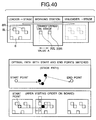
- the start point of a stage path is at the position to load from the loader to the stage, and the end point is at the position of the stage before moving to the unloader as shown in the upper part of Fig 40.
- a traveling salesman problem with fixed edge points may be solved to effectively shorten the stage operation time.
- the optimal path for the stage including the start and end points is shown in the middle part of Fig. 40, and the order of visiting on the board at the time (the area visiting direction on the board and the stage moving direction are 180° shifted (reversed) from one another) are shown in the lower part in Fig. 40.
- first and second galvano scanners 28L, 28R, 32L and 32R are provided so that one axis (the X- or Y- axis) independently changes the other axis. Therefore, the end of one scanning operation by the galvano scanners in one scanning area must be the end of scanning by both the first and second galvano scanners.
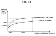
- the irradiation range to the second mirrors 30L and 30R is generally larger than the irradiation range to the first mirrors 26R and 26L, and therefore the second mirrors have a larger weight than the first mirrors do. Therefore as shown in Fig. 41, the response of the second mirrors is lower.
- the moving distance M from the perforation positions (x1, y1) to (x2, y2) can be obtained from the following expression (assuming that the moving time of the second mirror is a prescribed number ( ⁇ ') multiple of the moving time of the first mirror for the same distance).
- ⁇ ' is obtained by experiments.
- M max ⁇
- the moving distance M can be obtained based on the scanning angles ⁇ and ⁇ of the galvano mirrors from the following expression rather than based on the coordinates on the board.
- M max ⁇
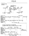
- the start points may be shifted for matching in step 603, so that the beam scanning time periods can be equal, and the total working time period can be shortened.
- the start and end points of the galvano path can be determined as shown in detail in Fig. 44 by applying the traveling salesman problem to determine a tour, so that the longest distance (the most time consuming) movement Lmax can be removed.
- a tour is determined as a substitute processing so as to minimize "(tour length)-(largest moving length)," and the longest movement can be excluded, in practice, as shown in Figs. 45 and 46.
- k-opt or Lin and Kernighan (LK) algorithm allows iteration of the loop of "searching the neighborhood of a solution (tour) and updating with a neighbor” and the solution is sequentially improved.
- “(tour length)-(largest moving length)- is evaluated as the "solution” of each loop rather than the "tour length”
- “(tour length)-(largest moving length)” is minimum as the final solution.
- the tour length is smaller on the right side, while if compared based on the "(tour length)-(largest moving length)," the left side is the optimal solution.
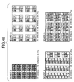
- Figs. 47 and 48 For some real board data, the results of applying the area placement planning device 74 to the entire board are given in Figs. 47 and 48.
- the processing of dividing the region into two with two units is not employed, and the entire board is used as a single area.
- the numerical results are given in Fig. 49. While the result differed depending upon various conditions such as the perforation position number and the density of points, a reduction from 10% to 30% in average in the area number was observed.
- the graph having the unit interval A for the abscissa as the X-axis is divided into two, the beam scanning number for the first ordinate and the stage moving number for the second ordinate is given in Fig. 50.
- the area placement planning device 74 is not used, and the scanning areas are determined according to the conventional method.
- the numerical results are given in Fig. 51.
- "halving,” "the head of pattern” correspond to the conventional methods.
- the beam scanning number is 24627, which is improved by about 5% as compared to those by the conventional methods (26111 for the halving, and about 27000 for the head of pattern).
- the stage moving number (71) is not much different between the optimal position and those by the conventional methods. This is because the area placement was determined based on the conventional area placement method which depends only on the longitudinal and transverse sizes. If the area placement is determined using the area placement planning device according to the present invention, the stage moving number should be different.
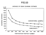
- Figs. 52 and 53 are diagrams where the abscissa represents the number of perforation positions, and the ordinate represents the average value of one movement by the galvano scanner.
- Fig. 54 the result by the conventional methods and that by the application of 3-opt well known as one of traveling salesman problem approaches are compared. A part of the result is given in Fig. 54.
- the average value of the distance by one movement of the galvano scanner was improved by about 30% to 40%.
- the stage total moving time is surely reduced and improved about by 20 to 30%.
- stage/galvano path planning device As describe above, application of the stage/galvano path planning device according to the present invention surely reduces the total moving time of the galvano scanner approximately by 30% to 40%.
- the planning device is characterized by an aspect related to combinatorial optimization such as traveling salesman problem, and a computational geometry aspect such as data search in a two-dimensional plane.
- these problems require enormous calculation time if the processing method is wrong.
- the geometrical point data such as perforation positions is analyzed and planned
- improvement to the precision of plans is tradeoff for time necessary for computation (operation by a CPU) in planning.
- the time consumed for computation should be enormous regardless of whether planning is executed as off-line or on-line processing, which increases the time necessary for the planning itself.
- the position data of points in a two-dimensional plane is for example represented in a tree data structure such as a k-dimensional binary search tree (abbreviated as kd-tree), so that the following processings at the working planning device for a laser drilling machine is operated at higher speed, and the time required for planning itself can be shortened.
- kd-tree k-dimensional binary search tree
- the kd-tree is one of data structures used for effectively performing point data search in a multi-dimensional space and expressed in the structure of a binary search tree well known as a data structure for effectively searching in a one-dimensional region in a multi-dimensionally generalized manner.
- the binary search tree is expressed in one of binary tree structures according to the graph theory.
- the searches include for example basic queries using database such as orthogonal range query, exact match query and partial match query.
- the binary tree is expressed in a form systematically widening downwardly from a special node (o) called root (denoted by R in the figure) arranged in the uppermost part. Therefore, the relation between nodes of a binary tree is typically expressed by terms for the kinship of animals and organisms as follows. For example, A is a "parent (father)" of C, D and E are “children” of B, D and E are “brothers,” A is an "ancestor” of F, and F is a "descendent" of A. Based on the definition of a binary tree, each node has two or less child nodes. A node without a child is called “leaf" node while the other nodes are called internal nodes (including roots).
- a typical binary search tree has the following structure.
- the internal node holds section information (segment) and a dividing value for dividing the segment into two (a position to divide the segment), while the kd-tree holds region information (rectangular region) and a dividing line for dividing the region into two (a line dividing the region into two and parallel to the length or width of the rectangle).
- section information segment
- kd-tree region information
- a dividing line for dividing the region into two
- the two-dimensional kd-tree allows variations in how to set a dividing axis, which is determined as follows according to the embodiment.
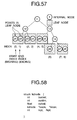
- Each node can be expressed as shown in Fig. 58 using structure types in the C language (C++ language).
- struct kdnode is a node
- bucket integer type
- cutdim integer type
- cutval floating point type or integer type
- lopt integer type
- hipt integer type
- Actual point data belonging to a region corresponded to each leaf node is for example stored in "perm[lopt,...,hipt]" for example using array.
- minimum necessary items to be held by each node are as follows.
- Rectangular range query is a process of listing points in a rectangular region within and a range of the rectangular region parallel to the frame as Fig. 57 shows.
- the search is used to list points in an area during or after the step of determining area positions on the process of determining the placement using the area placement planning device.
- top-down search is executed from the root node to leaf nodes of a tree. More specifically, if the node is an internal node, it is judged whether or not to search both child nodes of the node depending upon the degree of overlapping between the region corresponded to the node and the search region. The judgment is made as follows.
- node is a leaf node
- all the point data of the node is accessed and it is judged whether or not the points are within the search region and the points within the search region are sequentially reported.
- the point data is not directly accessed but top-down search from the root node to leaf nodes of a tree is conducted, and the judgment at each node is only about the degree of overlapping with the search region (inclusion, overlapping, no overlapping). Point data is directly accessed only when a leaf node is reached, so that the time for searching is surely reduced.
- the processings (2) to (4) are each closely related with increase in the operation speed for a traveling salesman problem.
- the processings (3) and (4) in particular both repeatedly use the processing (2), and therefore will be described together as follows.
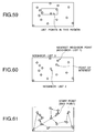
- the nearest neighbor query is a processing to search the point nearest to a point of interest in a region.
- the processing is repeatedly used in the process of (3) constructing a neighbor-list, and (4) the nearest neighbor.
- a prescribed number (list length: three in the example in Fig. 60) of points found are listed in the order of their nearness to the point of interest in the region.
- the processing is achieved by iteration of the nearest neighbor query and deleting temporarily removing a found neighbor from a tree.
- the processing is performed as a preparation of producing data to be attached to each point data so that the traveling salesman problem is solved at higher speed, and the processing is performed to all the points in the region.
- an initial point is appropriately determined as a point of interest, and the processing of "the neighbor point nearest to the point of interest and yet to be connected to a path is searched, and the found point is set as a new point of interest" is repeated until making a tour.
- the processing is achieved by iteration of the nearest neighbor query and the temporal deletion of a found nearest neighbor from a tree.
- the processing is advantageous because high speed processing is enabled, and a solution with relatively high precision (tour length) is secured. Therefore, the solution can be used as an initial solution (step 501) in using a solving method belonging to the kind of an iterated improvement method for the traveling salesman problem shown in Fig. 62.
- the distances between a point of interest in a region and all the points other than the point of interest in the region are calculated to obtain the nearest point.
- the distances between a point of interest in a region and all the points other than the point of interest in the region are calculated and arranged in a list starting from the point with the shortest distance for a list length.
- the distances between a point of interest and all the points yet to be connected to a path are calculated in each iteration and the nearest point is searched to update the point of interest.
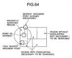
- top-down search will be described with reference to a particular processing process in conjunction with Fig. 63.
- the search is performed by recursively calling "the top-down search processing for a partial tree having the present node as a root.” More specifically, the part enclosed by the broken line corresponds to "the top-down search processing for a partial tree having the present node as a root," while in the processing, the present node is updated to the left or right node, so that the broken line part can be processed (steps 1005, 1006, 1009, 1010).
- step 1001 the present node is set as a root and the distance to the nearest neighbor point is set to a huge value. Then, in "the top-down search processing for a partial tree having the present node as a root,” it is judged in step 1002 whether the present node is a leaf node. If the present node is a leaf node, all the point data is accessed in step 1003, and if the nearest neighbor is found, updating is performed with the found point. If the present node is an internal node, it is determined in step 1004 which is to be searched with priority between left and right child node regions. The determination is based on the comparison between the dividing value of a dividing line for the present node ("cutval" in Fig.
- Steps 1007 and 1008 are performed to judge whether it is necessary or not to search a region corresponded to a brother node to the node searched immediately before.
- Fig. 64 it is judged whether or not there is an overlap between a circle centered on a point of interest whose nearest neighbor point is searched and having a radius as long as the distance to the present nearest neighbor point (here, the word "circle” refers to a closed curve consisting of points at an equal distance from the center and the distance measure does not have to be Euclidean distance) and the region corresponded to the node. (one may include the other.)
- a leaf node having a point of interest is set as the initial node for search, and a brother or parent node to the present node is searched as required.
- each node must be attached with a pointer to point the parent node. Therefore, in Fig. 58, a kdnode type pointer, "* father" is added as a structure type element. Note however that the root node does not have a father node, and therefore points "NULL".
- step 2001 the present node is set to a leaf node having a point of interest whose nearest neighbor is searched (therefore, each point data must have a pointer to point the leaf node where the data belongs), and the distance to the nearest neighbor is set to a huge value.
- step 2002 the present node is at a leaf node in practice, and therefore all the points in the present node are accessed to update the nearest neighbor.
- step 2003 it is judged whether or not search must be conducted outside the region represented by the present node. More specifically, it is judged whether or not a circle centered on a point of interest (whose nearest neighbor point is searched) and having a radius as long as the distance to the present nearest neighbor point is included in the region corresponded to the present node. If the circle is not included, the process enters the loop processing enclosed by the broken line.
- step 2005 it is judged whether or not the present node updated in step 2006 is a root node.
- step 2008 it is judged whether or not search must be conducted outside the region corresponded to the parent node of the present node. More specifically, similarly to step 2003, it is judged whether or not a circle centered on a point of interest whose nearest neighbor point is searched and having a radius as long as the distance to the present nearest neighbor is included in the region corresponded to the present node.
- step 2006 in the loop processing it is judged whether it is necessary or not to search a region corresponded to a brother node to the present node. More specifically, it is judged whether or not a circle centered on a point of interest whose nearest neighbor is searched and having a radius as long as the distance to the present nearest neighbor point overlaps the region corresponded to the present node. If there is an overlap, actual search is executed in step 2007.
- a point of interest is in a region D
- search is started from the region D having the point of interest Q1 according to the bottom-up method (step 2001).
- the distances from all the points to the point of interest Q1 are checked (step 2002), and if the found nearest neighbor point is Q2, then it is determined whether or not a circle centered at Q1 and having a radius as long as the distance between Q1 and Q2 is partly outside the region D (step 2003).
- the circle is not entirely within the region D, and therefore further search is necessary.
- the region D is not a region corresponded to a root node (entire region)(step 2005), and therefore it is then judged whether or not a region E, a brother region to the region D should be searched (step 2006).
- the judgment is based on the degree of overlapping with the circle, and since there is an overlap in this example, search is performed in the region E (step 2007). In this example, a point Q3 nearer to Q1 than Q2 is found in the region E.
- search in the regions D and the region E i.e., in the region B
- it is then determined whether or not a circle having a radius as long as the distance between the point of interest Q1 and the nearest neighbor point Q3 and centered on point Q1 is partly outside the region B step 2008.
- the circle is partly outside, and a brother region C to the region B must be searched, and therefore the present node is updated to a node representing region B (i.e., updated to a parent region to the region D) (step 2009), and the process returns to the step 2005.
- the nearest neighbor point Q4 is finally found in the region H, and the process is completed.
- a neighbor-list is constructed by alternately repeating the above two processings i.e., (2) nearest neighbor search, and the processing of "temporarily deleting a found nearest neighbor (point) from a tree.”
- a point data may temporarily be deleted from the tree as follows. More specifically, as shown in Fig. 58, a leaf node of a tree has the start and end numbers of an index attached to each point data. Therefore, basically, to delete a point, reduce (or increase) the end number (or the start number) by one, and exchange the data with the data at the position resulting from the reduction (or increase). If the point is removed and then the point data in the leaf node entirely disappear, information for the node is provided to indicate the disappearance of points in the region represented by its node ("empty" (integer type) is added to the element of a structure type for each node as shown in Fig. 58 in order to indicate the presence/absence of points) in order to eliminate the necessity of visiting the leaf node
- the nearest neighbor method is realized by alternately performing the nearest neighbor query in the above (2) and the processing of temporarily deleting a found nearest neighbor point from the tree similarly to (3). Unlike (3) according to which a point of interest is usually fixed, according to (4), a found nearest neighbor point is updated to a point of interest.
- all the other point data is accessed to calculate the distances from a point of interest, and the smallest result must be kept.
- all the other data must be accessed to operate to obtain the distances to the point of interest, and they must be sorted by the distance. The operation is performed to all the point data, and therefore the distances calculation operation is conducted to all the point data sets.
- points yet to be connected to a path must be recognized, all the point data must be accessed for distance calculation and the smallest data must be kept.
- the nearest neighbor query includes the top-down approach and the bottom-down approach.
- the bottom-up approach particularly allows direct access to a leaf node having a point of interest, which can significantly increase the operation speed.
- the neighbor-list In producing a neighbor-list, deleting point data from a tree can be achieved at high speed, and therefore the processing can be executed at much higher speed.
- the neighbor-list is produced as a preparation for increasing the speed of a method belonging to local search methods for a traveling salesman problem, and therefore though indirectly the speed of solving the traveling salesman problem could be increased.
- the operation speed can be increased for the same reason.
- the nearest neighbor method provides an initial solution to a method belonging to local search methods for a traveling salesman problem, and therefore the processing of solving the traveling salesman problem can partly be achieved at higher speed.
- Exact match query is to ask about the presence of a points having coordinates in exact match with a certain points in a region. Using the query, it can be judged whether or not the relative arrangement patterns in a certain scanning area and another scanning area are in exact match.
- All the perforation positions belong to one scanning area.
- the visiting order galvano path
- the amount of calculation by a traveling salesman problem is relatively larger than the rest, and therefore areas whose point positions are entirely equal among all the scanning areas, and an area which does not necessitate solution of a traveling salesman problem are searched. If such an area can be found and the necessity of solving a traveling salesman problem is eliminated, it immediately means an increase in the calculation speed.
- all the point positions do not have to be entirely the same for areas, and relative positional relation needs only be in coincidence for each points. More specifically, as shown in the upper part in Fig. 67, if all the point positions are exactly the same, and the galvano path for the area P is determined, there is no need to re-plan a path in the area Q. Similarly, when one point position is offset to the other point position like the relation between areas R and S in the lower part in Fig. 67, the path in the area R needs only be determined and the path in the area S does not have to be planned.
- the offset amount may be the difference between the absolute coordinates of representative points in both areas such as the minimum x and minimum y.
- the processing of judging point arrangement matching between scanning areas using the exact match query is performed when the area position is determined.
- all the points in a region are accessed and compared one by one with the coordinate values of a point of interest for matching.
- the offset amount between an area of interest and another area of interest is calculated, and then the presence of coordinates produced by adding the offset amount to the coordinates of each point in the area of interest in the other area of interest is searched from the root node of the other area of interest to a child node to the present node.
- the search is sequentially executed to the child node having the coordinates being searched.
- all the points in the node are compared one by one for matching.
- the kd-tree used according to the present invention is built from point position data, and a region in which the point position data is present. According to the embodiment, a kd-tree is built after a temporary region is produced using two-unit area placement planning device and the area position is defined.
- the orthogonal range query at the time of producing a temporary region is applied to point listing and the like in an area during the area position determination in the process of "area placement planning device.” Therefore, every time the loop is called by the optimal unit interval value determination processing, and the temporary region is produced, a tree related to the temporary region and the temporary point position data is formed.
- the nearest neighbor search, constructing a neighbor-list, and the nearest neighbor method are all related to the traveling salesman problem.
- the traveling salesman problem is generally used to optimize an area position visiting order (stage path) and a perforation position visiting order (galvano path) in a scanning area. Therefore, when an area position is defined, one tree related to a provisional region with the optimal unit interval value and point data is produced, while a tree related to a scanning area region and perforation positions as point data belonging to the scanning area is produced for each area.
- the tree related to each of the scanning areas is also used for exact match query described above.
- Programs in the working planning as described above are normally incorporated in software used by a laser working machine, but the calculation load is large and could adversely affect the operation of the working machine which cannot afford a high speed processing computer for calculation. Meanwhile, in order to use up-to-date programs, they must always be upgraded which may impose some costs on users. This also applies to the case of extracting a program for working planning and providing a single kind of software. Note that the working position data could be mailed from the user using a storage medium such as a flexible disc, and a working plan can be produced based on the data at the manufacturer's support center and sent back by mail. The exchange by mail takes too long a time period.
- the user's personal computer (hereinafter simply as “user PC") 82 provided on the side of a laser working machine 80, and a PC 90 capable of high speed processing provided at the laser working machine manufacturer's support center (referred to as “support center PC") for working planning only are connected through the Internet 100.
- the support center PC 90 determines working plans, and the determined plans are returned to the user PC 82 through the Internet 100.
- a browser 84 connects the user PC 82 to the Internet 100, and a web server 92 provides a home page on the Internet 100.
- Reference numerals 86 and 94 represent JAVA® applet, 88 CAD data for working positions, and 96 a working order optimization application used to determine working plans for the CAD data 88 transmitted from the user PC 82.
- step 3001 the user uses the browser 84 in the user PC 82 to access the homepage provided by the support center, and in step 3003, further accesses a conversion service page using HTML data returned from the support center in step 3002. Then, in response to a JAVA® applet instruction transmitted in step 3004, necessary conditions for conversion are input in step 3005, files whose working order is to be optimized are selected and transmitted to the support center PC 90 through the Internet 100.
- step 3006 the order of working data is optimally converted by the working order optimization application 96 based on the received data, and data files for the machine is produced.
- the files are returned again through the Internet 100.
- step 3007 the user transfers the received, converted data files to the laser working machine, and executes working.
- the conversion is executed on the support center side, and therefore the user can always use the up-to-date version of working plans, and use the high speed processing computers provided at the support center.
- the working planning programs for the machine handed to the user do not have to be frequently updated, in other words, the programs can readily be updated.
- the user information can easily be collected/stored.
- the user PC is supposed to be a single machine, separately provided from the laser working machine 80, while the number of user PCs or the placement positions thereof are not limited to those.
- a user PC 83 for CAD can be separately provided or as in a second variation shown in Fig. 71, the user PC 82 can be stored in the laser working machine 80.
- the number of galvano units is two, while the number of galvano units is not limited to this, and may be one, three or more.
- the areas each have a regular square shape of 40 mm ⁇ 40 mm, while the shape is not limited to this, and the areas may be a regular square, an oblong rectangle or a circle of a different size.
- the scanning direction is not limited to the typical scanning direction parallel to one side of the area as shown in the upper part in Fig. 72, but scanning may be performed in an oblique direction obtained by concentrically rotating the point coordinates as shown in the lower part in Fig 72.
- the means for scanning scanning areas with a laser beam is not limited to the device with a galvano scanner, and may be a hybrid working system (so-called “screen cut system” or “flush cut system”) including a combination of a linear monitor XY stage and a high speed working head as suggested by the applicant in Japanese Patent Laid-Open Nos. 2000-71089, and 2000-334637.
- a hybrid working system so-called “screen cut system” or "flush cut system” including a combination of a linear monitor XY stage and a high speed working head as suggested by the applicant in Japanese Patent Laid-Open Nos. 2000-71089, and 2000-334637.
- the invention is by all means applicable to general working machines (such as a drilling machine with a mechanical drill) using working means other than those with a laser beam such as the laser drilling machine described above.
- the communication line is not limited to the Internet but a private line or a telephone line may be used.
Landscapes
- Physics & Mathematics (AREA)
- Optics & Photonics (AREA)
- Engineering & Computer Science (AREA)
- Plasma & Fusion (AREA)
- Mechanical Engineering (AREA)
- Human Computer Interaction (AREA)
- Geometry (AREA)
- Manufacturing & Machinery (AREA)
- General Physics & Mathematics (AREA)
- Automation & Control Theory (AREA)
- Numerical Control (AREA)
- Laser Beam Processing (AREA)
- Complex Calculations (AREA)
- Feedback Control In General (AREA)
Abstract
Description
Claims (69)
- A method of working planning in allocating a plurality of working positions scattered on a workpiece to a plurality of working areas to be simultaneously worked, said method comprising the steps of:determining an optimal working path for working positions in each working area; andsubsequently determining order of working at the working positions in each working area so that the total working time is minimized in the working areas to be simultaneously worked.
- A method of working planning in determining order of working at a plurality of working areas scattered on a workpiece, said method comprising the step of:shifting an start point of a working path in each of the plurality of simultaneous working areas so that time for scanning or moving simultaneously performed can be equal, thereby shortening a total working time.
- A working planning method in determining order of working by applying a traveling salesman problem to a plurality of working positions scattered on a workpiece or working areas set in a workpiece, said method comprising the steps of:solving the traveling salesman problem, thereby minimizing a length of a tour; andsubsequently detecting a longest movement, and determining start and end points so that the longest movement is removed.
- A working planning method in determining order of working by applying a traveling salesman problem to a plurality of working positions scattered on a workpiece or working areas set in a workpiece, said method comprising the steps of:solving a traveling salesman problem to minimize a value produced by removing a longest movement from a tour, thereby obtaining a new tour, andeventually removing the longest movement, and determining start and end points.
- A working planning method in determining placement of working areas to be worked by working means based on working positions scattered on a workpiece, said method comprising the steps of:provisionally setting a next working area so as to enclose an end point in a first direction not yet enclosed by the working area;moving said provisionally set working area in a second direction different from said first direction to enclose an end point in the second direction;again moving said moved working area in the first direction so as to enclose the end point in said first direction in positions after the movement; andagain moving the re-moved working area in the second direction so as to enclose the end point in said second direction in positions after the re-movement, whereinsaid steps of moving are repeated to define the next working area.
- The working planning method according to claim 5, wherein said working area has a square frame orthogonal to said first and second directions.
- The working planning method according to claim 5 or 6, wherein said first and second directions are set to correspond to the moving direction of a workpiece.
- A method of working planning in determining placement of working areas to be worked by working means based on working positions scattered on a workpiece, said method comprising the steps of:simply dividing an entire surface of the workpiece into the working areas; andsubsequently removing all the working areas without any working position.
- A working planning method in determining placement of working areas to be worked by working means based on working positions scattered on a workpiece, said method comprising the step of:repeating the step of placing a working area in a position with a largest number of working positions not yet enclosed until all the working positions are enclosed.
- A working planning method, in determining placement of working areas to be worked by working means based on working positions scattered on a workpiece, said method comprising the steps of:provisionally determining area placement; andsubsequently shifting a working area to a neighborhood andremoving an unnecessary working area.
- The working planning method according to claim 10, wherein said area placement is provisionally determined by the method according to claim 5.
- The working planning method according to claim 10, wherein said area placement is provisionally determined by the method according to claim 8.
- The working planning method according to claim 10, wherein said area placement is provisionally determined by the method according to claim 9.
- The working planning method according to claim 10, wherein said working area is shifted to a neighborhood and an unnecessary neighboring area is removed, provided that a point independently belonging to said working area stays within the area.
- The working planning method according to claim 10, wherein among said working areas, at least two areas joined at an overlapping location are each shifted to a neighborhood and an unnecessary neighboring area is removed, provided that a point independently belonging to said at least two areas stays within said working areas.
- A working planning method in determining placement of working areas to be worked by working means based on working positions scattered on a workpiece, said method comprising,
when the same working position belongs to a plurality of areas, determining said areas to be worked so that number of working positions belonging to each of a plurality of simultaneous working areas is equal. - The working planning method according to claim 16, whereinsome of the working positions belonging to said plurality of areas are allocated to an area having a greater difference among a plurality of simultaneous working areas, some of the remaining working positions are allocated to a area having a smaller difference, andeventually remaining working positions are distributed equally among both areas.
- A working planning method in determining placement of working areas to be worked by working means based on working positions scattered on a workpiece, said method comprising the step of:adjusting an area position so that working positions are gathered to center of each working areas.
- The working planning method according to claim 18, wherein area position is adjusted so that center of an extent of said working positions matches center of the working area.
- The working planning method according to claim 18, wherein area position is set as near as center of gravity of the working positions, provided that the working positions are within the working area.
- A working planning method in working a workpiece placed on a stage, said stage being movable in a plurality of directions, said method comprising the step of:determining a moving path for said stage by solving a traveling salesman problem with fixed edge points in which a position to load the workpiece to the stage from a loader is set as a start point of the moving path for said stage,a position before moving the workpiece to an unloader is set as an end point.
- A working planning method in simultaneously working a workpiece placed on a movable stage by a plurality of working units capable of scanning or moving working means within a working area, said method comprising the step of:determining an interval between the working units so that number of scanning or moving the working means or number of moving the stage is minimized.
- The working planning method according to claim 22, wherein the number of scanning or moving said working means and the number of moving the stage are weighted depending on difference in scanning or moving time.
- The working planning method according to claim 22 or 25, further comprising the steps of:setting the interval of said working units;overlapping scanning or moving ranges of the working units at that time, thereby obtaining area placement to minimize number of working areas; andcalculating the number of scanning or moving of the working means and the number of moving the stage at the time.
- A working planning method, comprising the steps of:performing the process according to claim 22 in a different workpiece direction; andautomatically employing the workpiece direction which minimizes the number of scanning or moving the working means or the number of moving the stage.
- A working planning method in working a workpiece using working means capable of scanning or moving in a plurality of directions, wherein point position data representing working positions or working areas scattered on the workpiece is expressed in a tree type data structure.
- The working planning method according to claim 26, wherein said tree is a k-dimensional binary search tree.
- The working planning method according to claim 26 or 27, wherein said tree is used to list point data in each working area after the position of working areas scattered on the workpiece is determined.
- The working planning method according to claim 26, wherein from a root node of said tree, for internal nodes, whether or not to search a child node of a node is judged based on the degree of overlapping between a region corresponding to the child node of the node and a search region, and only when a leaf node is reached, the point data is directly accessed.
- The working planning method according to claim 26 or 27, wherein process of searching nearest neighbor point to a point of interest is conducted using said tree.
- The working planning method according to claim 30, wherein said process of searching the nearest neighbor point is started from a root node of said tree.
- The working planning method according to claim 31, wherein a node is searched when a circle centered on the point of interest and having a radius as long as distance to present nearest neighbor point overlaps a region corresponding to the node.
- The working planning method according to claim 32, wherein
if said node is a leaf node, distances to all the points corresponding to the node in the region are obtained, and it is judged whether each distance is short. - The working planning method according to claim 30, wherein
each point data piece has information related to a leaf node to which said data piece belongs,
said process of searching the nearest neighbor point is performed by directly accessing the leaf node having the point of interest whose nearest neighborhood is searched, and then the search is performed in a direction toward the root node of said tree, only if there is a node to be searched. - The working planning method according to claim 34, wherein
if a circle centered on the point of interest and having a radius as long as distance to present nearest neighbor point and a region corresponding to a node are outside a region corresponding to the present node, a brother node thereof or a brother node of a parent node thereof is searched depending on a degree of how much outside they are. - The working planning method according to claim 30, wherein said process of searching said nearest neighbor point and process of searching next nearest neighbor point, using a tree removed of a found nearest neighbor point are repeated, so that neighbor points are listed in order of their nearness to the point of interest.
- The method of working planning according to claim 30, wherein process of searching the nearest neighbor point not yet connected to a working path by said process of searching the nearest neighbor point and connecting a new found point of interest to the working path, and process of searching next nearest neighbor point using the tree removed of the found point of interest and connecting a next new found point of interest to the working path are repeated from a start point to an end point to produce the working path.
- The working planning method according to claim 36 or 37, wherein the process of removing a found point from said tree is performed by reducing ending number of an index attached to each point data or by increasing starting number.
- The working planning method according to claim 38, wherein
if a found point is removed from said tree, and all point data in a node disappears, the node is attached with information indicating that it is not necessary to visit the node. - A working planning method, wherein a working path determined by a working planning method according to any one of claims 37 to 39 is set as an initial solution in determining order of working by applying a traveling salesman problem.
- A working planning method, wherein
an unnecessary, high load operation is removed by finding a set of areas in which placement of point data in one of the working areas and placement of point data in another working area are relatively matched. - The working planning method according to claim 41, wherein said process of searching a set of areas having relatively matched point data placements is performed by the steps of:producing point position data by adding a prescribed coordinate shift to all the points in one area;visiting one node after another corresponding to a region having said point position data from a root node of a tree in the other area; andchecking whether or not there is point position data matched with said point position data only when a leaf node is reached.
- The working planning method according to claim 26 or 27, wherein
in the process of enclosing point data in the working area with the minimum number of equal size rectangles, every time a provisional working area is produced by calling a loop, said tree is built both for the provisional working area and provisional point position data in each working area. - The working planning method according to claim 26 or 27, wherein said tree is built both for the working area and point position data in each working area when the working area is defined.
- A working method performing working determined by the working planning method according to any one of claims 1 to 44.
- A computer program for implementing the working planning method according to any one of claims 1 to 44.
- A working planning device for allocating a plurality of working positions scattered on a workpiece to a plurality of working areas to be simultaneously worked, said device comprising:working path determining means for determining an optimal working path for working positions in each working area; andworking order determining means for determining order of working in the working positions in each working area so that the total working time in the working areas to be simultaneously worked is minimized.
- A working planning device for planning working in determining order of working in a plurality of working areas scattered on a workpiece, comprising,
working order shift means for shifting a start point of a working path for each of the plurality of simultaneous working areas so that time for scanning or moving performed simultaneously can be equal among the simultaneous working areas, and shortening the total working time. - A working planning device for planning working in determining order of working by applying a traveling salesman problem to a plurality of working positions scattered on a workpiece or working areas set in the workpiece, comprising,
scanning path determining means for detecting a longest movement after minimizing a round path by solving the traveling salesman problem, and determining start and end points so that the longest movement is removed. - A working planning device for planning working in determining order of working by applying a traveling salesman problem to a plurality of working positions scattered on a workpiece or working areas set in the workpiece, comprising,
scanning path determining means for solving a traveling salesman problem improved to minimize a value produced by removing longest movement from a tour, thereby obtaining tour, and eventually removing the longest movement to determine start and end points. - A working planning device for planning working in determining placement of working areas to be worked by working means based on working positions scattered on a workpiece, said device comprising,
area placement determining means for repeating a process for defining a next working area,
said process including provisionally setting the next working area so as to enclose an end point in a first direction not yet enclosed by the working area; moving the provisionally set working area in a second direction different from the first direction so that the area encloses an end point in the second direction; again moving said moved working area in the first direction so that the area encloses the end point in said first direction, and again moving said re-moved working area in said second direction so that the area encloses the end point in said second direction in a position after the re-movement. - A working planning device for planning working in determining placement of working areas to be worked by working means based on working positions scattered on a workpiece, comprising,
area placement determining means for simply dividing an entire surface of a workpiece into working areas, and removing all the working areas having no working position. - A working planning device for planning working in determining placement of working areas to be worked by working means based on working positions scattered on a workpiece, comprising,
area placement determining means for repeating a process of placing a working area in a position having the largest number of working positions not yet enclosed until all the working positions are enclosed. - A working planning device for planning working in determining placement of working areas to be worked by working means based on working positions scattered on a workpiece, comprising,
area placement determining means for provisionally determining area placement, shifting a working area to a neighborhood, and removing an unnecessary working area. - A working planning device for planning working in determining placement of working areas to be worked by working means based on working positions scattered on a workpiece, comprising,
belonging area determining means for determining a working area, when same working positions belong to a plurality of working areas, said means determining the areas so that number of working positions belonging to each of the plurality of simultaneous working areas is equal. - A working planning device for working planning in determining placement of working areas to be worked by working means based on working positions scattered on a workpiece, comprising,
area placement adjusting means for adjusting area positions so that working positions are gathered around the center of each working area. - A working planning device for planning working in working a workpiece placed on a stage movable in a plurality of directions, comprising,
moving path determining means for determining a moving path for said stage by solving a traveling salesman problem with fixed edge points wherein a position to load a workpiece to the stage from a loader being set as an start point of the moving path for said stage, a position before transferring the workplace to an unloader being set as an end point. - A working planning device for planning working in working a workpiece placed on a movable stage simultaneously using a plurality of working units capable of scanning working means in a working area, comprising, unit interval determining means for determining an interval of the working units so that number of scanning or moving the working means or number of moving the stage is minimized.
- The working planning device according to claim 58, further comprising,
workpiece direction determining means for performing the processing by said unit interval determining means in a different workpiece direction, and automatically employing a workpiece direction allowing the number of scanning or moving the working means or the number of moving the stage to be minimized. - A working planning device for planning working in working a workpiece using working means capable of scanning or moving in a plurality of directions, comprising:means for storing point position data on points representing working positions or working areas scattered on the workpiece, said data being expressed in a tree type data structure; andmeans for determining working area positions and/or order of working using the position data expressed in said tree type data structure.
- A working device comprising the working planning device according to any one of claims 47 to 60.
- A computer program for implementing the working planning device according to any one of claims 47 to 60.
- A working data producing method, comprising the steps of:determining a working plan based on working position data received from a working device side through a communication line; andreturning the plan to said working device side.
- The working data producing method according to claim 63, wherein
said working plan is determined by the method according to any one of claims 1 to 44. - A computer program for implementing the working data producing method according to claim 63 or 64.
- A working data producing device, comprising:means for receiving working position data from a working device side through a communication line;planning means for determining a working plan based on the received working position data; andtransmission means for transmitting the determined working plan back to said working device side.
- The working data producing device according to claim 66, wherein
said working plan is determined by the method according to any one of claims 1 to 44. - A computer program for implementing the working data producing device according to claim 66 or 67.
- A computer readable recording medium recorded with the computer program according to any one of claims 46, 62, 65 and 68.
Applications Claiming Priority (8)
| Application Number | Priority Date | Filing Date | Title |
|---|---|---|---|
| JP2000345417 | 2000-11-13 | ||
| JP2000345417 | 2000-11-13 | ||
| JP2000359553 | 2000-11-27 | ||
| JP2000359553 | 2000-11-27 | ||
| JP2001243870 | 2001-08-10 | ||
| JP2001243870 | 2001-08-10 | ||
| JP2001331550A JP3774138B2 (en) | 2000-11-13 | 2001-10-29 | Process planning method and apparatus, and process method and apparatus |
| JP2001331550 | 2001-10-29 |
Publications (2)
| Publication Number | Publication Date |
|---|---|
| EP1211583A2 true EP1211583A2 (en) | 2002-06-05 |
| EP1211583A3 EP1211583A3 (en) | 2005-03-09 |
Family
ID=27481770
Family Applications (1)
| Application Number | Title | Priority Date | Filing Date |
|---|---|---|---|
| EP01126892A Withdrawn EP1211583A3 (en) | 2000-11-13 | 2001-11-12 | Method and device for working planning |
Country Status (5)
| Country | Link |
|---|---|
| US (1) | US20030028407A1 (en) |
| EP (1) | EP1211583A3 (en) |
| JP (1) | JP3774138B2 (en) |
| CN (1) | CN1357428A (en) |
| HK (1) | HK1047720A1 (en) |
Cited By (2)
| Publication number | Priority date | Publication date | Assignee | Title |
|---|---|---|---|---|
| CN113618262A (en) * | 2021-10-12 | 2021-11-09 | 江油星联电子科技有限公司 | Aluminum-based printed circuit board is with cutting material device |
| CN115249088A (en) * | 2022-05-27 | 2022-10-28 | 北京石油化工学院 | LED crystal grain sorting path planning method based on greedy algorithm |
Families Citing this family (38)
| Publication number | Priority date | Publication date | Assignee | Title |
|---|---|---|---|---|
| JP3427380B2 (en) * | 2001-02-09 | 2003-07-14 | 株式会社大日光・エンジニアリング | Network system, method for purchasing purchased product using network system, plug-in software for client internet browser in network system, and method for purchasing purchased product using plug-in software for client internet browser in network system |
| JP3816815B2 (en) * | 2001-09-27 | 2006-08-30 | 株式会社東芝 | Charged particle beam exposure method and charged particle beam exposure data creation method |
| JP4201159B2 (en) * | 2002-01-29 | 2008-12-24 | 大日本スクリーン製造株式会社 | Drawing apparatus and imaging apparatus |
| JP2003245843A (en) * | 2002-02-21 | 2003-09-02 | Hitachi Via Mechanics Ltd | Processing device and method |
| KR100486410B1 (en) * | 2002-04-29 | 2005-04-29 | 주식회사 미르기술 | Auto-teaching method for printed circuit board part mounting inspection system |
| JP4227427B2 (en) * | 2003-01-29 | 2009-02-18 | 三菱電機株式会社 | Laser processing equipment |
| EP1533651A4 (en) * | 2003-03-28 | 2007-03-07 | Seiko Epson Corp | SPACE LIGHT MODULATOR, PROJECTOR USING SAME, METHOD FOR MANUFACTURING FINE STRUCTURE ELEMENT USED IN THE MODULATOR, AND FINE STRUCTURE ELEMENT MADE THEREBY |
| US7521651B2 (en) * | 2003-09-12 | 2009-04-21 | Orbotech Ltd | Multiple beam micro-machining system and method |
| JP4544911B2 (en) * | 2004-05-31 | 2010-09-15 | ヤマハファインテック株式会社 | Processing apparatus and printed circuit board production method |
| JP4514519B2 (en) * | 2004-05-31 | 2010-07-28 | ヤマハファインテック株式会社 | Printed circuit board production method, processing apparatus, and processing program |
| ATE538417T1 (en) * | 2006-05-19 | 2012-01-15 | Siemens Industry Inc | AUTOMATIC SETTING OF A CLOSED LOOP |
| JP4943070B2 (en) * | 2006-06-29 | 2012-05-30 | 株式会社キーエンス | Laser processing device, laser processing condition setting device, laser processing condition setting method, laser processing condition setting program |
| JP4891878B2 (en) * | 2007-09-25 | 2012-03-07 | 日立ビアメカニクス株式会社 | Processing equipment |
| JP4509174B2 (en) * | 2007-12-27 | 2010-07-21 | 三菱電機株式会社 | Laser processing apparatus and laser processing control apparatus |
| DE102008016734A1 (en) | 2008-03-31 | 2009-10-08 | Trumpf Werkzeugmaschinen Gmbh + Co. Kg | Method for optimizing the occupancy of a pipe or several pipes with several pipe parts to be cut for a processing plant |
| US8461479B2 (en) * | 2009-12-23 | 2013-06-11 | Electro Scientific Industries, Inc. | Adaptive processing constraints for memory repair |
| JP5745367B2 (en) * | 2011-08-31 | 2015-07-08 | パナソニック デバイスSunx株式会社 | Laser processing equipment |
| KR102048361B1 (en) * | 2013-02-28 | 2019-11-25 | 엘지전자 주식회사 | Distance detecting device and Image processing apparatus including the same |
| JP6164917B2 (en) * | 2013-05-10 | 2017-07-19 | キヤノン株式会社 | Article processing apparatus, generation method, and program |
| JP2015010948A (en) * | 2013-06-28 | 2015-01-19 | キヤノン株式会社 | Article processing device, generation method, and program |
| US9703915B2 (en) * | 2014-07-24 | 2017-07-11 | Mitsubishi Electric Research Laboratories, Inc. | Method for determining a sequence for drilling holes according to a pattern using global and local optimization |
| JP6411865B2 (en) * | 2014-11-06 | 2018-10-24 | ローランドディー.ジー.株式会社 | Cutter moving path determining device, cutting system, and cutter moving path determining method |
| KR101542018B1 (en) * | 2014-11-17 | 2015-08-05 | 성균관대학교산학협력단 | Method for laser machining with optimized moving route |
| JP6510829B2 (en) * | 2015-02-05 | 2019-05-08 | 株式会社ディスコ | Laser processing equipment |
| JP6374336B2 (en) * | 2015-03-20 | 2018-08-15 | ビアメカニクス株式会社 | Laser processing apparatus and laser processing method |
| JP2017100168A (en) * | 2015-12-03 | 2017-06-08 | キヤノン株式会社 | Laser processing device, component manufacturing method, program and recording medium |
| JP6647888B2 (en) * | 2016-01-29 | 2020-02-14 | ビアメカニクス株式会社 | Laser processing method and laser processing apparatus |
| EP3474199B1 (en) * | 2017-10-20 | 2021-05-05 | CL Schutzrechtsverwaltungs GmbH | Method for operating an apparatus for additively manufacturing of three-dimensional objects |
| JP7088742B2 (en) * | 2018-05-18 | 2022-06-21 | キヤノン電子株式会社 | Processing system, processing machine, processing machine control method and program |
| JP6823016B2 (en) * | 2018-07-17 | 2021-01-27 | ファナック株式会社 | Numerical control device |
| US11315053B1 (en) * | 2020-02-13 | 2022-04-26 | Tensorx, Inc. | Systems and methods for optimizing complex systems |
| CN111822887B (en) * | 2020-07-14 | 2022-04-26 | 深圳中科光子科技有限公司 | Processing system and method for laser drilling thick glass |
| CN112836854B (en) * | 2020-12-31 | 2022-10-21 | 合肥工业大学 | Optimization method of sheet porous machining path based on greedy algorithm |
| CN114548610B (en) * | 2022-04-27 | 2022-07-08 | 季华实验室 | Automatic arrangement method and device for engine cover outer plate stamping process |
| CN115041842B (en) * | 2022-06-28 | 2023-03-07 | 广东工业大学 | Method and system for optimizing laser drilling path of chip group holes |
| CN114971087A (en) * | 2022-07-25 | 2022-08-30 | 杭州凌像科技有限公司 | Method and system for optimizing traversal disordered finite point set path for laser drilling machine |
| CN115841499A (en) * | 2022-10-20 | 2023-03-24 | 东方晶源微电子科技(北京)有限公司 | Contour acquisition method and device for SEM image, computer equipment and storage medium |
| CN115548176B (en) * | 2022-11-07 | 2026-02-10 | 錼创显示科技股份有限公司 | Processing operation methods and processing systems of processing equipment |
Family Cites Families (9)
| Publication number | Priority date | Publication date | Assignee | Title |
|---|---|---|---|---|
| CA2038939C (en) * | 1989-08-10 | 1997-06-17 | Satomi Furukawa | Production control system |
| EP0523270A1 (en) * | 1991-07-18 | 1993-01-20 | International Business Machines Corporation | Method to control a positioning system |
| US5293025A (en) * | 1991-08-01 | 1994-03-08 | E. I. Du Pont De Nemours And Company | Method for forming vias in multilayer circuits |
| JP3461532B2 (en) * | 1993-07-02 | 2003-10-27 | 松下電器産業株式会社 | How to determine the mounting order |
| JPH0798609A (en) * | 1993-09-28 | 1995-04-11 | Toyoda Mach Works Ltd | Working allocation deciding device for two torch type laser beam machine |
| JPH0798608A (en) * | 1993-09-28 | 1995-04-11 | Toyoda Mach Works Ltd | Working route deciding device for two torch type laser beam machine |
| JPH10258373A (en) * | 1997-01-16 | 1998-09-29 | Nikon Corp | Processing equipment and laser processing equipment |
| JPH11149317A (en) * | 1997-11-14 | 1999-06-02 | Nikon Corp | Processing equipment |
| JP2001195112A (en) * | 2000-01-12 | 2001-07-19 | Sumitomo Heavy Ind Ltd | Laser drilling path determination method |
-
2001
- 2001-10-29 JP JP2001331550A patent/JP3774138B2/en not_active Expired - Fee Related
- 2001-11-12 EP EP01126892A patent/EP1211583A3/en not_active Withdrawn
- 2001-11-13 US US09/986,911 patent/US20030028407A1/en not_active Abandoned
- 2001-11-13 CN CN01137439A patent/CN1357428A/en active Pending
-
2002
- 2002-12-31 HK HK02109451.1A patent/HK1047720A1/en unknown
Cited By (3)
| Publication number | Priority date | Publication date | Assignee | Title |
|---|---|---|---|---|
| CN113618262A (en) * | 2021-10-12 | 2021-11-09 | 江油星联电子科技有限公司 | Aluminum-based printed circuit board is with cutting material device |
| CN113618262B (en) * | 2021-10-12 | 2021-12-14 | 江油星联电子科技有限公司 | Aluminum-based printed circuit board is with cutting material device |
| CN115249088A (en) * | 2022-05-27 | 2022-10-28 | 北京石油化工学院 | LED crystal grain sorting path planning method based on greedy algorithm |
Also Published As
| Publication number | Publication date |
|---|---|
| JP3774138B2 (en) | 2006-05-10 |
| US20030028407A1 (en) | 2003-02-06 |
| CN1357428A (en) | 2002-07-10 |
| EP1211583A3 (en) | 2005-03-09 |
| JP2003131714A (en) | 2003-05-09 |
| HK1047720A1 (en) | 2003-03-07 |
Similar Documents
| Publication | Publication Date | Title |
|---|---|---|
| US20030028407A1 (en) | Method and device for working planning, and method and device for producing working data therefor | |
| US9697317B1 (en) | Integrated circuits having in-situ constraints | |
| Cohoon et al. | Distributed genetic algorithms for the floorplan design problem | |
| US6442745B1 (en) | Method and apparatus for layout-constrained global routing | |
| US8341586B2 (en) | Method and system for routing | |
| Preas et al. | Automatic placement a review of current techniques | |
| EP1405228B1 (en) | Two dimensional compaction system and method | |
| WO2001024111A1 (en) | Automatic routing system for pc board design | |
| Chen et al. | A hybrid simulated annealing algorithm for nonslicing VLSI floorplanning | |
| JP2004529402A5 (en) | ||
| US8627255B2 (en) | Methods and systems for flexible and repeatable pre-route generation | |
| KR20240152907A (en) | Integrated circuits having non-preferred direction curved wiring | |
| Vörös | Low-cost implementation of distance maps for path planning using matrix quadtrees and octrees | |
| Cuellar‐Usaquén et al. | Modeling and solving the endpoint cutting problem | |
| KR100463097B1 (en) | Method And Device For Working Planning, And Method And Device For Producing Working Data Therefor | |
| US7877718B2 (en) | Analog IC placement using symmetry-islands | |
| JP2004253006A (en) | Process planning method and apparatus, and process method and apparatus | |
| Singh et al. | A binary particle swarm optimization for IC floorplanning | |
| Ganovelli et al. | Animating cuts with on-the-fly re-meshing | |
| Sait et al. | Timing-influenced general-cell genetic floorplanner | |
| Ying et al. | An analytical approach to floorplanning for hierarchical building blocks layout (VLSI) | |
| Koakutsu et al. | Genetic simulated annealing and application to non-slicing floorplan design | |
| JP3999796B2 (en) | Process planning method and apparatus, and process method and apparatus | |
| JP4091019B2 (en) | Process planning method | |
| TW200302761A (en) | Method of planning machining and machining equipment |
Legal Events
| Date | Code | Title | Description |
|---|---|---|---|
| PUAI | Public reference made under article 153(3) epc to a published international application that has entered the european phase |
Free format text: ORIGINAL CODE: 0009012 |
|
| AK | Designated contracting states |
Kind code of ref document: A2 Designated state(s): AT BE CH CY DE DK ES FI FR GB GR IE IT LI LU MC NL PT SE TR |
|
| AX | Request for extension of the european patent |
Free format text: AL;LT;LV;MK;RO;SI |
|
| PUAL | Search report despatched |
Free format text: ORIGINAL CODE: 0009013 |
|
| AK | Designated contracting states |
Kind code of ref document: A3 Designated state(s): AT BE CH CY DE DK ES FI FR GB GR IE IT LI LU MC NL PT SE TR |
|
| AX | Request for extension of the european patent |
Extension state: AL LT LV MK RO SI |
|
| RIC1 | Information provided on ipc code assigned before grant |
Ipc: 7B 23K 26/38 B Ipc: 7H 05K 3/00 B Ipc: 7G 06F 17/60 B Ipc: 7G 05B 19/18 B Ipc: 7G 05B 19/418 A |
|
| AKX | Designation fees paid | ||
| REG | Reference to a national code |
Ref country code: DE Ref legal event code: 8566 |
|
| STAA | Information on the status of an ep patent application or granted ep patent |
Free format text: STATUS: THE APPLICATION IS DEEMED TO BE WITHDRAWN |
|
| 18D | Application deemed to be withdrawn |
Effective date: 20050910 |