EP1211573A2 - Heating device having resin layer over core metal of heating roller - Google Patents
Heating device having resin layer over core metal of heating roller Download PDFInfo
- Publication number
- EP1211573A2 EP1211573A2 EP01127474A EP01127474A EP1211573A2 EP 1211573 A2 EP1211573 A2 EP 1211573A2 EP 01127474 A EP01127474 A EP 01127474A EP 01127474 A EP01127474 A EP 01127474A EP 1211573 A2 EP1211573 A2 EP 1211573A2
- Authority
- EP
- European Patent Office
- Prior art keywords
- heating roller
- ball bearing
- resin layer
- fixing roller
- heating
- Prior art date
- Legal status (The legal status is an assumption and is not a legal conclusion. Google has not performed a legal analysis and makes no representation as to the accuracy of the status listed.)
- Granted
Links
Images


Classifications
-
- F—MECHANICAL ENGINEERING; LIGHTING; HEATING; WEAPONS; BLASTING
- F16—ENGINEERING ELEMENTS AND UNITS; GENERAL MEASURES FOR PRODUCING AND MAINTAINING EFFECTIVE FUNCTIONING OF MACHINES OR INSTALLATIONS; THERMAL INSULATION IN GENERAL
- F16C—SHAFTS; FLEXIBLE SHAFTS; ELEMENTS OR CRANKSHAFT MECHANISMS; ROTARY BODIES OTHER THAN GEARING ELEMENTS; BEARINGS
- F16C35/00—Rigid support of bearing units; Housings, e.g. caps, covers
- F16C35/04—Rigid support of bearing units; Housings, e.g. caps, covers in the case of ball or roller bearings
- F16C35/06—Mounting or dismounting of ball or roller bearings; Fixing them onto shaft or in housing
- F16C35/07—Fixing them on the shaft or housing with interposition of an element
- F16C35/077—Fixing them on the shaft or housing with interposition of an element between housing and outer race ring
-
- F—MECHANICAL ENGINEERING; LIGHTING; HEATING; WEAPONS; BLASTING
- F16—ENGINEERING ELEMENTS AND UNITS; GENERAL MEASURES FOR PRODUCING AND MAINTAINING EFFECTIVE FUNCTIONING OF MACHINES OR INSTALLATIONS; THERMAL INSULATION IN GENERAL
- F16C—SHAFTS; FLEXIBLE SHAFTS; ELEMENTS OR CRANKSHAFT MECHANISMS; ROTARY BODIES OTHER THAN GEARING ELEMENTS; BEARINGS
- F16C35/00—Rigid support of bearing units; Housings, e.g. caps, covers
- F16C35/04—Rigid support of bearing units; Housings, e.g. caps, covers in the case of ball or roller bearings
- F16C35/06—Mounting or dismounting of ball or roller bearings; Fixing them onto shaft or in housing
- F16C35/07—Fixing them on the shaft or housing with interposition of an element
- F16C35/073—Fixing them on the shaft or housing with interposition of an element between shaft and inner race ring
-
- G—PHYSICS
- G03—PHOTOGRAPHY; CINEMATOGRAPHY; ANALOGOUS TECHNIQUES USING WAVES OTHER THAN OPTICAL WAVES; ELECTROGRAPHY; HOLOGRAPHY
- G03G—ELECTROGRAPHY; ELECTROPHOTOGRAPHY; MAGNETOGRAPHY
- G03G15/00—Apparatus for electrographic processes using a charge pattern
- G03G15/20—Apparatus for electrographic processes using a charge pattern for fixing, e.g. by using heat
- G03G15/2003—Apparatus for electrographic processes using a charge pattern for fixing, e.g. by using heat using heat
- G03G15/2014—Apparatus for electrographic processes using a charge pattern for fixing, e.g. by using heat using heat using contact heat
- G03G15/2053—Structural details of heat elements, e.g. structure of roller or belt, eddy current, induction heating
Definitions
- the present invention relates to a heating device in which a heating roller heated at high temperature is brought into contact with a member to be heated, and more particularly to the heating device used in a fixing process of a toner image in an electrophotographic printing process and an image forming apparatus, such as a printer, a copier, etc., having the heating device in a fixing section thereof.
- an electrostatic latent image formed on a surface of a photoconductive element is developed with toner.
- the developed toner image is transferred onto a transfer sheet.
- a fixing process is performed to fix the toner image onto the transfer sheet.
- the toner image is fixed onto the transfer sheet by at least heat and pressure.
- the transfer sheet having the toner image is conveyed while being sandwiched by a fixing roller and a pressure roller.
- the fixing roller is heated to a high temperature.
- the pressure roller is driven while being press-contacted with the fixing roller.
- the toner image on the transfer sheet is then fixed while the transfer sheet is conveyed by the fixing roller.
- the fixing roller is formed into a drum shape having a heater inside, it is advantageous that the fixing roller has a decreased thickness to shorten a period of time required for a warm-up operation. However, if the thickness of the fixing roller is decreased, a large amount of deformation appears. Thus, a wrinkle of a transfer sheet tends to occur.
- a value of the ratio of thickness to outer diameter ("thickness/outer diameter") of an image region (i.e., a central portion of the fixing roller through which a transfer sheet is conveyed) of the fixing roller needs to be in a predetermined range according to a size of a diameter of the fixing roller.
- an outer diameter of a portion of the fixing roller, which is supported by a bearing provided on a main body of the apparatus is smaller than that of the image region thereof.
- a noise is produced when the resin layer or ceramic member is rubbed against the core metal and ball bearing if the resin layer or ceramic member is conventionally provided as a separate part.
- the production of the noise may be reduced using a grease; however, a fluorine grease for a high-temperature is expensive.
- a fluorine grease for a high-temperature is expensive.
- an insulating effect is enhanced, however, resulting not only in an increase in costs but in a further production of the noise.
- the thickness of the fixing roller is determined such that the value of "thickness/outer diameter" of the image region is in the predetermined range.
- the thickness of the supported portion of the fixing roller needs to be adjusted based on the determined thickness of the image region of the fixing roller to obviate a deformation of the fixing roller and an occurrence of a wrinkle of a transfer sheet.
- an inner diameter of the supported portion of the fixing roller is set to a value equal to that of the inner diameter of the image region. Therefore, when a design change is made in the thickness of the supported portion, an outer diameter of the supported portion is ultimately changed.
- a general-purpose ball bearing is not used, and a customized ball bearing that fits the modified outer diameter of the supported portion of the fixing roller is required.
- the outer diameter of the supported portion is smaller than that of the image region.
- the supported portion is then supported by a bearing provided on a main body of the apparatus.
- a replacement of the fixing roller with new one is not easily performed without dismantling a relating component.
- the present invention has been made in view of the above-mentioned and other problems and addresses the above-discussed and other problems.
- the present invention advantageously provides a novel image forming apparatus having a heating device used in a fixing operation of a toner image in an electrophotographic printing process, wherein a production of a noise, caused by a rubbing of the resin layer (which is provided between a core metal of a fixing roller and a ball bearing to suppress a conduction of heat from the fixing roller to the ball bearing) against the ball bearing and core metal of the fixing roller, is obviated.
- a material of the resin layer is selected and the resin layer is configured to have a rough surface so as to have a coefficient of dynamic friction of the resin surface at a predetermined value.
- a thickness of a supported portion of the fixing roller is determined based on a thickness of an image region of the fixing roller to prevent a deformation of the fixing roller.
- An inner diameter of the supported portion of the fixing roller is smaller than that of the image region so that an outer diameter of the supported portion of the fixing roller is not changed even if the thickness of the supported portion of the fixing roller is changed, so that a general-purpose ball bearing can be used.
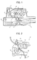
- Fig. 1 is a schematic drawing illustrating a construction of a printer as an image forming apparatus according to an example of the present invention.
- the image forming apparatus includes a fixing device which includes a heating device of the present invention.
- Fig. 2 is a schematic drawing illustrating a construction of the fixing device. Referring to Fig. 1, the construction and operation of the image forming apparatus is described below along a flow of a transfer sheet on which an image is formed.
- the transfer sheet fed from a sheet feeding device 5 is conveyed to a photoconductive element 4 (which is belt-shaped in this example) on a surface of which an image (i.e., an electrostatic latent image) is formed.
- a photoconductive element 4 which is belt-shaped in this example
- the registration roller 6 conveys the transfer sheet by adjusting the timing such that the transfer sheet is in precise register with the image formed on the surface of the photoconductive element 4.
- the photoconductive element 4 is driven in a clockwise direction.
- Devices performing a respective electrophotographic printing process are arranged along a run of the photoconductive element 4.
- the surface of the photoconductive element 4 is charged by a charger 2.
- a laser writing optical system 1 irradiates the surface of the charged photoconductive element 4 with a scanning beam modulated according to image data so as to form an electrostatic latent image thereon.
- the electrostatic latent image is developed into a visible image with toner by a developing device 3.
- the visible image is then transferred onto a transfer sheet by a transfer charger 7.
- the transfer sheet which is brought into a press-contact with the photoconductive element 4 in a transfer process, is separated from the photoconductive element 4 at a curvature of the photoconductive element 4.
- the transfer sheet is then conveyed to a fixing device 8 so that the image is fixed.
- the transfer sheet is discharged to a sheet discharging tray 9.
- Residual charge remaining on the photoconductive element 4 is discharged by a discharging lamp 10.
- Residual toner remaining on the surface of the photoconductive element 4 is removed by a cleaning device 11.
- AC (Alternating Current) and DC (Direct Current) power required for the above-described series of operations is supplied from a power source 12.
- the fixing device 8 fixes a toner image, which has been transferred onto a transfer sheet from the photoconductive element 4 in an image transfer process, by applying at least heat and pressure.
- the fixing device 8 is heated to a high temperature.
- the fixing device 8 includes a fixing roller 14 (i.e., a heating roller) and a pressure roller 16.
- the fixing roller 14 rotatably drives and the pressure roller 16 is rotatably driven by the rotation of the fixing roller 14 while press-contacting with the fixing roller 14.
- the transfer sheet having the toner image is conveyed through a nip formed between the fixing and pressure rollers 14 and 16. Thus, the toner image is fixed onto the transfer sheet.
- the fixing device 8 includes the fixing roller 14, the pressure roller 16, a cleaning pad 18, a switching pick 17, a pressure spring 15, and a fixing device inlet guide plate 19.
- the fixing device 8 further includes a gear (not shown) to drive the fixing roller 14, a bearing (not shown) for the fixing roller 14, and a thermistor (not shown).
- a reference numeral "20" denotes a transfer sheet 20.
- the fixing roller 14 is employed in the heating device of the present invention.
- Fig. 3 is a schematic drawing illustrating a construction of the heating device. Both end portions of the fixing roller 14 are rotatably supported by a ball bearing 21.
- a driving gear 14g is provided at one end of the fixing roller 14 beyond the ball bearing 21.
- the fixing roller 14 is driven via the driving gear 14g.
- a diameter of a portion of a circumferential surface of the fixing roller 14 which is supported by the ball bearing 21 i.e., a supported portion
- a diameter of a portion of a circumferential surface of the fixing roller 14 which is supported by the ball bearing 21 i.e., a supported portion
- a diameter of a portion of a circumferential surface of the fixing roller 14 which is supported by the ball bearing 21 is equal to that of the circumferential surface of an image region thereof (i.e., a central portion of the fixing roller 14 through which a transfer sheet is conveyed).
- the diameter of the circumferential surface of the portion of the fixing roller 14 which is supported by the ball bearing 21 is not smaller than that of the circumferential surface of the fixing roller 14 of the image region, unlike a conventional fixing roller.
- the fixing roller 14 is pulled out in an axial direction by removing retaining rings 14r, which are provided approximately at both edges of the fixing roller 14 to regulate a movement of the fixing roller 14 in the axial direction.
- a replacement of the fixing roller 14 with a new one is easily performed without removing parts provided on a main body of the apparatus, such as the ball bearing 21.
- the fixing roller 14 includes a core metal made of iron (i.e., STKM11, STKM12) or an aluminum alloy having a diameter of 16mm to 40mm and a length of 350mm to 410mm.
- the thickness is set in a range of 8/1000 to 14/1000 when the core metal is made of iron, and when the core metal is made of aluminum alloy the thickness is set in a range of 10/1000 to 20/1000.
- the value of "thickness/outer diameter” is small, the degree of the deformation of the fixing roller 14 becomes great. Thus, a wrinkle of a transfer sheet tends to be generated.
- the value of "thickness/outer diameter” is large, a comparatively long period of time is required before the fixing roller 14 is heated to a required temperature for a fixing operation, resulting in a longer warm-up time for the fixing operation.
- the transfer sheet 20 is conveyed by a rotation of the fixing roller 14.
- the pressure roller 16 includes an elastic layer over a core substrate.
- the diameter of the pressure roller 16 is 30mm.
- a thickness and length of the elastic layer is set to 5.5mm and 316mm, respectively.
- the elastic layer is either sponge-formed or solid-formed (i.e., non-sponge).
- the used fixing roller 14 includes a core metal made of iron (i.e., STKM12) having an outer diameter of 30mm.
- a thickness of an image region of the fixing roller 14 is 0.3mm.
- a value of "thickness/outer diameter” is 10/1000.
- Another used fixing roller includes the core metal made of aluminum alloy (i. e., A5052). The outer diameter is 30mm and the thickness of the image region is 0.45mm. The value of "thickness/outer diameter" is 15/1000.
- a length of the fixing roller 14 is 365mm. Accordinging to the example, a warm-up time is shortened to 10 to 15 seconds when a heater 13 has 700 to 800 watts of power.
- the ball bearing 21 is advantageous to use as a bearing to support the fixing roller 14 when the fixing roller 14 is rotated at a high speed.
- a driving torque is increased in the early stages of use, and especially over the course of time.
- the driving torque is not significantly increased when the ball bearing 21 is used.
- a motor which is smaller than that employed when the resin sliding bearing is used, can be used because the driving torque is reduced, resulting in a reduction in costs.
- a resin layer i.e., a resin member
- a resin layer is provided between the core metal of the fixing roller and the ball bearing, for heat insulation.
- FIG. 4A is a drawing illustrating a vertical sectional view of the fixing roller 14 in which the resin layer 22 is adhered to the core metal 24 of the fixing roller 14.
- Fig. 4B is a drawing illustrating a enlarged view of a part of the fixing roller 14.
- Fig. 4A is a drawing illustrating a transverse sectional view of the fixing roller 14.
- Fig. 4B is a drawing illustrating an enlarged view of a level difference formed in the portion of the fixing roller 14 where the diameter of the circumferential surface changes.
- a resin layer 22 is adhered to a core metal 24 via a primer layer 23.
- the resin layer 22 is layered on both portions of circumferential surfaces of the fixing roller, namely, the portion where the circumferential surface is supported by the ball bearing 21 (i.e., the supported portion) and the portion of the circumferential surface that is the image region.
- the same surface layer which has a necessary property (i.e., mainly a release effect) for the surface that contacts a transfer sheet) which is layered on the image region is layered on the circumferential surface of the supported portion of the fixing roller 14.
- a resin having a high thermal insulative property may be layered only on the circumferential surface of the supported portion of the fixing roller 14.
- a production of a noise caused by a rubbing of the resin layer 22 (which is constructed integrally with the core metal 24 of the fixing roller 14) against the ball bearing 21 is obviated.
- a clearance of 0.04mm to 0.15mm is created between the ball bearing 21 and the resin layer 22 because the fixing roller 14 expands with temperature.
- Fig. 6 is a drawing illustrating a perspective view of the ball bearing 21.
- the ball bearing 21 includes an outer ring 21o and an inner ring 21i.
- the resin layer 22 of the fixing roller 14 cannot be rubbed against the inner ring 21i of the ball bearing 21 because the outer ring 210o is fixed to a main body of the apparatus and the inner ring 21i rotates.
- a noise may be produced in practice because (1) the above-described clearance is created, and (2) the torque of the fixing roller 14 varies when a transfer sheet is conveyed between the fixing roller 14 and the pressure roller 16, and when no transfer sheet is conveyed therebetween. Then, a friction coefficient value at which the production of the noise is suppressed is ascertained, while paying particular attention to a coefficient of dynamic friction of the surface of the resin layer 22.
- a resin having a high insulative property may be layered only on the circumferential surface of the supported portion of the fixing roller 14.
- the resin layer 22 including a fluororesin is integrally layered on both the image region and supported portion of the fixing roller 14.
- the fluororesin is layered mainly to have a release effect.
- This fluororesin layer 22 is adhered to the core metal 24 of the fixing roller 14 via the primer layer 23 (i.e., an adhesion layer).
- a material that has a coefficient of dynamic friction of 0.2 to 0.5 (when the fixing roller 14 moves at the speed of 50mm/s having a load of 7Kgf/cm 2 ), such as a perfluoroalkoxy resin, tetrofluoroethylene resin, a mixture of these two resins, or resins produced by adding an additive or a reinforcement agent (such as carbon or glass fiber) to the respective resins may be used.
- the surface of the resin layer 22 is made as rough as possible while the above-described coefficient of dynamic friction is maintained in a proper range.
- Fig. 7 is a drawing illustrating a vertical sectional view of the ball bearing 21 and the resin layer 22 that includes a rough surface. As illustrated in Fig.
- the resin layer 22 has roughness on the surface that contacts the inner ring 21i of the ball bearing 21.
- the surface roughness (Rz) of the resin layer 22 is set to 3 to 12 ⁇ m.
- Fig. 8A is a drawing illustrating a polishing operation of the fixing roller 14. As illustrated in Fig.
- the polishing of the surface of the fixing roller 14 is performed by moving a reel of the polishing tape in a direction indicated by an arrow "A" while the polishing tape is brought into contact with the surface of the fixing roller 14 which rotates in a direction indicated by an arrow "B".
- an inconvenience such as the polishing tape snagging on the different level portion 14c or the fluororesin of the corner of the different level portion 14c being scraped may be caused.
- the different level portion is tapered instead of being formed having a right angle so that the polishing of the fixing roller 14 is easily performed using the polishing tape.
- Fig. 4B shows the enlarged tapered different level portion.
- a corner of the tapered different level portion is configured to have a curve 15R having a radius of 0.5mm to 1.5mm, thereby obviating the scrape of the fluororesin of the corner of the different level portion.
- the value in a range of one and half to three times (i.e., 1.5 to 3 times) the thickness of the image region is selected as the value of the thickness of the supported portion.
- the thickness of the supported portion is set to 0.9mm to 1.0mm.
- the thickness of the image region is consequentially determined in order to achieve a shortened warm-up time of the fixing roller 14. Then, an inner diameter of the core metal 24 of the image region is determined based on these values. However, if the appropriate value of thickness of the supported portion of the fixing roller 14 is determined based on the thickness of the image region thereof as described above, the outer diameter of the supported portion may be changed due to a design change in the thickness of the image region and the supported portion. Thus, it may happen that a general-purpose ball bearing (i.e., an inner diameter of a ball bearing is fixed) cannot be used, and an expensive customized ball bearing is required.
- a general-purpose ball bearing i.e., an inner diameter of a ball bearing is fixed
- the inner diameter of the supported portion of the fixing roller 14 is made smaller than that of the image region thereof so that the outer diameter of the supported portion is not changed even if the thickness of the supported portion is changed. Then, the general-purpose ball bearing is used because the outer diameter of the supported portion of the fixing roller 14 is not changed, thereby avoiding an increase in costs.
- a numerical value actually adopted to a fixing roller is described below, referring to Figs. 4A and 4B.
- the inner diameter of the image region "d2" - the inner diameter of the supported portion "d1" /2 0.3mm to 0.5mm.
- the length between the thick portion "A” and the thin portion "B” in the axial direction “L” is set to 1mm to 3mm such that the thickness does not steeply change in the direction of the length.
Landscapes
- Engineering & Computer Science (AREA)
- General Engineering & Computer Science (AREA)
- Mechanical Engineering (AREA)
- Physics & Mathematics (AREA)
- General Physics & Mathematics (AREA)
- Fixing For Electrophotography (AREA)
- Rolls And Other Rotary Bodies (AREA)
- Control Of Resistance Heating (AREA)
Abstract
Description
Claims (14)
- A heating device, comprising:wherein a resin layer (22) is adhesively provided to a surface of a portion of a core member (24) of the heating roller (14) which is supported by the ball bearing (21), and wherein a roughness of the surface of the resin layer (22) that contacts the ball bearing (21) is set to a predetermined value in which a production of a noise caused by a rubbing of the resin layer against the ball bearing is suppressed and a insulating effect is enhanced.a heating roller (14) configured to contact a heated member; anda ball bearing (21) configured to support the heating roller (14),
- The heating device according to claim 1, wherein a coefficient of dynamic friction of a surface of the resin layer (22) is set to a predetermined value in which the production of the noise caused by the rubbing of the resin layer (22) against the ball bearing (21) is suppressed.
- The heating device according to claim 1 or 2, wherein the resin layer (22) layered over the supported portion of the heating roller (14) is layered integrally with the layer over the surface of the portion of the core member (24) contacting the heated member.
- The heating device according to any one of claims 1 to 3, wherein an outer diameter of the supported portion of the heating roller (14) is equal to or larger than an outer diameter of the portion of the heating roller contacting the heated member.
- The heating device according to any one of claims 1 to 4, wherein a thickness of the supported portion of the heating roller (14) is larger than a thickness of the portion of the heating roller (14) contacting the heated member.
- A heating device, comprising:wherein an outer diameter of a portion of the heating roller (14) that is supported by the ball bearing (21) is equal to or larger than an outer diameter of a portion of the heating roller (14) that contacts the heated member.a heating roller (14) configured to contact a heated member; anda ball bearing (21) configured to support the heating roller (14),
- The heating device according to any one of claims 4 to 6, wherein when the outer diameter of the supported portion of the heating roller (14) is larger than the outer diameter of the portion of the heating roller (14) contacting the heated member, a portion of the supported portion of the heating roller (14) that is connected to the portion of the heating roller (14) contacting the heated member is tapered.
- The heating device according to claim 7, wherein a corner of an end of the tapered portion of the heating roller (14) is configured to have a circular curve.
- A heating device, comprising:wherein the heating roller (14) is configured such that a thickness of a portion of the heating roller (14) that is supported by the ball bearing (21) is larger than a thickness of a portion of the heating roller (14) that contacts the heated member.a heating roller (14) configured to contact a heated member; anda ball bearing (21) configured to support the heating roller (14),
- The heating device according to claim 5, 7, 8, or 9, wherein the thickness of the supported portion of the heating roller (14) is determined such that an outer diameter of the supported portion of the heating roller (14) is maintained at a predetermined value when the thickness of the supported portion of the heating roller (14) is larger than the thickness of the portion of the heating roller (14) contacting the heated member (16).
- An image forming apparatus, comprising:an image bearing member configured to form a latent image; andany one of the heating devices cited in claims 1 to 10, to perform a fixing operation.
- A method for obviating a production of a noise caused by a rubbing of a core member (24) of a heating roller (14) against a ball bearing (21) that supports a portion of the core member (24) of the heating roller (14) in a heating device, the method comprising:providing a resin layer (22) between the supported portion of the core member (24) of the heating roller and a ball bearing (21) supporting the supported portion of the core member (24) of the heating roller (14); andsetting a roughness of a surface of the resin layer (22) that contacts the ball bearing (21) to a predetermined value.
- A method for enhancing a replaceability of a heating roller (14) in a heating device, the method comprising:wherein an outer diameter of a portion of the heating roller (14) that is supported by the ball bearing (21) is equal to or larger than an outer diameter of a portion of the heating roller (14) that contacts the heated member.providing a heating roller (14) to contact a heated member; andproviding a ball bearing (21) to support a portion of a core member (24) of the heating roller (14),
- A method for obviating a deformation of a heating roller (14) in a heating device, the method comprising:wherein the heating roller (14) is configured such that a thickness of a portion of the heating roller (14) that is supported by the ball bearing (21) is larger than a thickness of a portion of the heating roller (14) that contacts the heated member.providing a heating roller (14) to contact a heated member; andproviding a ball bearing (21) to support a portion of a core member (24) of the heating roller (14),
Applications Claiming Priority (2)
| Application Number | Priority Date | Filing Date | Title |
|---|---|---|---|
| JP2000362912 | 2000-11-29 | ||
| JP2000362912A JP2002169397A (en) | 2000-11-29 | 2000-11-29 | Heating device and image forming device |
Publications (3)
| Publication Number | Publication Date |
|---|---|
| EP1211573A2 true EP1211573A2 (en) | 2002-06-05 |
| EP1211573A3 EP1211573A3 (en) | 2002-07-10 |
| EP1211573B1 EP1211573B1 (en) | 2005-07-20 |
Family
ID=18834109
Family Applications (1)
| Application Number | Title | Priority Date | Filing Date |
|---|---|---|---|
| EP01127474A Expired - Lifetime EP1211573B1 (en) | 2000-11-29 | 2001-11-28 | Heating device having resin layer over core metal of heating roller |
Country Status (4)
| Country | Link |
|---|---|
| US (2) | US6701120B2 (en) |
| EP (1) | EP1211573B1 (en) |
| JP (1) | JP2002169397A (en) |
| DE (1) | DE60112025T2 (en) |
Cited By (2)
| Publication number | Priority date | Publication date | Assignee | Title |
|---|---|---|---|---|
| US6701120B2 (en) * | 2000-11-29 | 2004-03-02 | Ricoh Company, Ltd. | Heating device having a heating roller with a large diameter portion which supports bearings |
| WO2014134582A3 (en) * | 2013-02-28 | 2014-10-23 | Battelle Memorial Institute | Gas seals for high temperature rotating shaft applications |
Families Citing this family (4)
| Publication number | Priority date | Publication date | Assignee | Title |
|---|---|---|---|---|
| FR2884306B1 (en) * | 2005-04-07 | 2007-05-11 | Stein Heurtey | COOLED ROLL FOR HANDLING STEEL PRODUCTS |
| WO2011017121A1 (en) * | 2009-07-27 | 2011-02-10 | Acciona Solar Power, Inc. | Scalable solar power plant |
| KR20120068267A (en) * | 2010-12-17 | 2012-06-27 | 삼성전자주식회사 | Fixing unit and image forming apparatus |
| CN107676374A (en) * | 2017-11-08 | 2018-02-09 | 张家港市华申工业橡塑制品有限公司 | Quick heat radiating anti-dropout rubber rollers |
Family Cites Families (17)
| Publication number | Priority date | Publication date | Assignee | Title |
|---|---|---|---|---|
| JPS6039868A (en) | 1983-08-15 | 1985-03-01 | Oki Electric Ind Co Ltd | Manufacturing method of semiconductor device |
| JPS62116980A (en) * | 1985-11-18 | 1987-05-28 | Canon Inc | Fusing device |
| JP2550554B2 (en) * | 1987-02-04 | 1996-11-06 | ミノルタ株式会社 | Heating element roll for fixing |
| JPH0719100B2 (en) * | 1989-06-22 | 1995-03-06 | キヤノン株式会社 | Fixing device |
| US5404214A (en) * | 1992-07-31 | 1995-04-04 | Canon Kabushiki Kaisha | Image heating apparatus comprising a grounded film |
| US5298957A (en) * | 1992-11-25 | 1994-03-29 | Xerox Corporation | Fuser roll apparatus having a heat stabilizing collar |
| JPH07168472A (en) * | 1993-09-27 | 1995-07-04 | Ntn Corp | Fixing roller support structure for heat fixing device |
| JPH07217644A (en) * | 1994-01-28 | 1995-08-15 | Sutaaraito Kogyo Kk | Roll for fixing device in copying machine or the like |
| JPH08101596A (en) * | 1994-09-30 | 1996-04-16 | Ricoh Co Ltd | Heat roller fixing device |
| US5585909A (en) * | 1995-07-31 | 1996-12-17 | Xerox Corporation | Flame sprayed ceramic end caps |
| JP3527349B2 (en) * | 1996-01-23 | 2004-05-17 | 株式会社リコー | Surface heating roller |
| JPH1097151A (en) * | 1996-09-19 | 1998-04-14 | Ricoh Co Ltd | Fixing roller |
| US6002897A (en) * | 1996-11-20 | 1999-12-14 | Mita Industrial Co. | Image-forming machine with photosensitive drum mount |
| US5987296A (en) * | 1997-09-24 | 1999-11-16 | Konica Corporation | Fixing device with heat roller having heating resistor layer therein |
| US6101363A (en) * | 1997-12-24 | 2000-08-08 | Brother Kogyo Kabushiki Kaisha | Thermal fixing device with stationary and rotational electrodes |
| US6463252B2 (en) * | 2000-07-04 | 2002-10-08 | Konica Corporation | Fixing device employing an induction heating method |
| JP2002169397A (en) * | 2000-11-29 | 2002-06-14 | Ricoh Co Ltd | Heating device and image forming device |
-
2000
- 2000-11-29 JP JP2000362912A patent/JP2002169397A/en active Pending
-
2001
- 2001-11-28 EP EP01127474A patent/EP1211573B1/en not_active Expired - Lifetime
- 2001-11-28 DE DE60112025T patent/DE60112025T2/en not_active Expired - Lifetime
- 2001-11-29 US US09/995,563 patent/US6701120B2/en not_active Expired - Lifetime
-
2003
- 2003-11-12 US US10/704,548 patent/US6969252B2/en not_active Expired - Fee Related
Cited By (2)
| Publication number | Priority date | Publication date | Assignee | Title |
|---|---|---|---|---|
| US6701120B2 (en) * | 2000-11-29 | 2004-03-02 | Ricoh Company, Ltd. | Heating device having a heating roller with a large diameter portion which supports bearings |
| WO2014134582A3 (en) * | 2013-02-28 | 2014-10-23 | Battelle Memorial Institute | Gas seals for high temperature rotating shaft applications |
Also Published As
| Publication number | Publication date |
|---|---|
| US6701120B2 (en) | 2004-03-02 |
| US20040126728A1 (en) | 2004-07-01 |
| EP1211573B1 (en) | 2005-07-20 |
| DE60112025T2 (en) | 2006-04-20 |
| EP1211573A3 (en) | 2002-07-10 |
| US20020064407A1 (en) | 2002-05-30 |
| JP2002169397A (en) | 2002-06-14 |
| US6969252B2 (en) | 2005-11-29 |
| DE60112025D1 (en) | 2005-08-25 |
Similar Documents
| Publication | Publication Date | Title |
|---|---|---|
| JP4933002B2 (en) | Heat fixing device and metal sleeve for heating | |
| US8676101B2 (en) | Fixing device having metal pipe with rough section and image forming apparatus incorporating same | |
| CN100422874C (en) | Fixing device and image forming device | |
| JP4498369B2 (en) | Image heating apparatus and flexible sleeve used in the image heating apparatus | |
| JP2003156954A (en) | Image heating apparatus having metal rotator contacting heater, rotator and method of manufacturing rotator | |
| JP2007249186A5 (en) | ||
| JP2004144833A (en) | Heating equipment | |
| US20110100972A1 (en) | Image heating apparatus | |
| EP1211573B1 (en) | Heating device having resin layer over core metal of heating roller | |
| US9639036B2 (en) | Image heating apparatus having a rubbing rotatable member | |
| JP6486059B2 (en) | Roller, fixing device | |
| JP2009251311A (en) | Fixing device and image forming apparatus having the same | |
| JP2007072105A (en) | Fixing apparatus and image forming apparatus | |
| JP2006243497A (en) | Fixing device | |
| JP6822117B2 (en) | Fixing device and image forming device | |
| JP7066460B2 (en) | Fixing device | |
| JP2003086333A (en) | Heating device and image forming device | |
| JP6665665B2 (en) | Fixing device and image forming device | |
| JP2010139984A (en) | Fixing device and image forming apparatus with the same | |
| JPH0235986B2 (en) | TEICHAKUSOCHI | |
| JP2004157442A (en) | Heating equipment | |
| JP5445836B2 (en) | Fixing apparatus and image forming apparatus | |
| JPH10123869A (en) | Fixing device | |
| JP2006091452A (en) | Fixing device | |
| JP2004144971A (en) | Heating equipment |
Legal Events
| Date | Code | Title | Description |
|---|---|---|---|
| PUAI | Public reference made under article 153(3) epc to a published international application that has entered the european phase |
Free format text: ORIGINAL CODE: 0009012 |
|
| PUAL | Search report despatched |
Free format text: ORIGINAL CODE: 0009013 |
|
| AK | Designated contracting states |
Kind code of ref document: A2 Designated state(s): AT BE CH CY DE DK ES FI FR GB GR IE IT LI LU MC NL PT SE TR |
|
| AX | Request for extension of the european patent |
Free format text: AL;LT;LV;MK;RO;SI |
|
| AK | Designated contracting states |
Kind code of ref document: A3 Designated state(s): AT BE CH CY DE DK ES FI FR GB GR IE IT LI LU MC NL PT SE TR |
|
| AX | Request for extension of the european patent |
Free format text: AL;LT;LV;MK;RO;SI |
|
| 17P | Request for examination filed |
Effective date: 20021114 |
|
| AKX | Designation fees paid |
Designated state(s): DE FR GB |
|
| 17Q | First examination report despatched |
Effective date: 20040820 |
|
| GRAP | Despatch of communication of intention to grant a patent |
Free format text: ORIGINAL CODE: EPIDOSNIGR1 |
|
| GRAS | Grant fee paid |
Free format text: ORIGINAL CODE: EPIDOSNIGR3 |
|
| GRAA | (expected) grant |
Free format text: ORIGINAL CODE: 0009210 |
|
| AK | Designated contracting states |
Kind code of ref document: B1 Designated state(s): DE FR GB |
|
| REG | Reference to a national code |
Ref country code: GB Ref legal event code: FG4D |
|
| REF | Corresponds to: |
Ref document number: 60112025 Country of ref document: DE Date of ref document: 20050825 Kind code of ref document: P |
|
| ET | Fr: translation filed | ||
| PLBE | No opposition filed within time limit |
Free format text: ORIGINAL CODE: 0009261 |
|
| STAA | Information on the status of an ep patent application or granted ep patent |
Free format text: STATUS: NO OPPOSITION FILED WITHIN TIME LIMIT |
|
| 26N | No opposition filed |
Effective date: 20060421 |
|
| REG | Reference to a national code |
Ref country code: FR Ref legal event code: PLFP Year of fee payment: 15 |
|
| REG | Reference to a national code |
Ref country code: FR Ref legal event code: PLFP Year of fee payment: 16 |
|
| PGFP | Annual fee paid to national office [announced via postgrant information from national office to epo] |
Ref country code: DE Payment date: 20161121 Year of fee payment: 16 Ref country code: FR Payment date: 20161118 Year of fee payment: 16 Ref country code: GB Payment date: 20161122 Year of fee payment: 16 |
|
| REG | Reference to a national code |
Ref country code: DE Ref legal event code: R119 Ref document number: 60112025 Country of ref document: DE |
|
| GBPC | Gb: european patent ceased through non-payment of renewal fee |
Effective date: 20171128 |
|
| REG | Reference to a national code |
Ref country code: FR Ref legal event code: ST Effective date: 20180731 |
|
| PG25 | Lapsed in a contracting state [announced via postgrant information from national office to epo] |
Ref country code: DE Free format text: LAPSE BECAUSE OF NON-PAYMENT OF DUE FEES Effective date: 20180602 Ref country code: FR Free format text: LAPSE BECAUSE OF NON-PAYMENT OF DUE FEES Effective date: 20171130 |
|
| PG25 | Lapsed in a contracting state [announced via postgrant information from national office to epo] |
Ref country code: GB Free format text: LAPSE BECAUSE OF NON-PAYMENT OF DUE FEES Effective date: 20171128 |