EP1211424A2 - Vacuum pump - Google Patents
Vacuum pump Download PDFInfo
- Publication number
- EP1211424A2 EP1211424A2 EP01309808A EP01309808A EP1211424A2 EP 1211424 A2 EP1211424 A2 EP 1211424A2 EP 01309808 A EP01309808 A EP 01309808A EP 01309808 A EP01309808 A EP 01309808A EP 1211424 A2 EP1211424 A2 EP 1211424A2
- Authority
- EP
- European Patent Office
- Prior art keywords
- pump
- rotor
- temperature
- vacuum pump
- vacuum
- Prior art date
- Legal status (The legal status is an assumption and is not a legal conclusion. Google has not performed a legal analysis and makes no representation as to the accuracy of the status listed.)
- Withdrawn
Links
Images


Classifications
-
- F—MECHANICAL ENGINEERING; LIGHTING; HEATING; WEAPONS; BLASTING
- F04—POSITIVE - DISPLACEMENT MACHINES FOR LIQUIDS; PUMPS FOR LIQUIDS OR ELASTIC FLUIDS
- F04B—POSITIVE-DISPLACEMENT MACHINES FOR LIQUIDS; PUMPS
- F04B37/00—Pumps having pertinent characteristics not provided for in, or of interest apart from, groups F04B25/00 - F04B35/00
- F04B37/06—Pumps having pertinent characteristics not provided for in, or of interest apart from, groups F04B25/00 - F04B35/00 for evacuating by thermal means
-
- F—MECHANICAL ENGINEERING; LIGHTING; HEATING; WEAPONS; BLASTING
- F04—POSITIVE - DISPLACEMENT MACHINES FOR LIQUIDS; PUMPS FOR LIQUIDS OR ELASTIC FLUIDS
- F04D—NON-POSITIVE-DISPLACEMENT PUMPS
- F04D29/00—Details, component parts, or accessories
- F04D29/58—Cooling; Heating; Diminishing heat transfer
- F04D29/582—Cooling; Heating; Diminishing heat transfer specially adapted for elastic fluid pumps
- F04D29/584—Cooling; Heating; Diminishing heat transfer specially adapted for elastic fluid pumps cooling or heating the machine
-
- F—MECHANICAL ENGINEERING; LIGHTING; HEATING; WEAPONS; BLASTING
- F04—POSITIVE - DISPLACEMENT MACHINES FOR LIQUIDS; PUMPS FOR LIQUIDS OR ELASTIC FLUIDS
- F04D—NON-POSITIVE-DISPLACEMENT PUMPS
- F04D19/00—Axial-flow pumps
- F04D19/02—Multi-stage pumps
- F04D19/04—Multi-stage pumps specially adapted to the production of a high vacuum, e.g. molecular pumps
-
- F—MECHANICAL ENGINEERING; LIGHTING; HEATING; WEAPONS; BLASTING
- F04—POSITIVE - DISPLACEMENT MACHINES FOR LIQUIDS; PUMPS FOR LIQUIDS OR ELASTIC FLUIDS
- F04D—NON-POSITIVE-DISPLACEMENT PUMPS
- F04D27/00—Control, e.g. regulation, of pumps, pumping installations or pumping systems specially adapted for elastic fluids
-
- F—MECHANICAL ENGINEERING; LIGHTING; HEATING; WEAPONS; BLASTING
- F05—INDEXING SCHEMES RELATING TO ENGINES OR PUMPS IN VARIOUS SUBCLASSES OF CLASSES F01-F04
- F05D—INDEXING SCHEME FOR ASPECTS RELATING TO NON-POSITIVE-DISPLACEMENT MACHINES OR ENGINES, GAS-TURBINES OR JET-PROPULSION PLANTS
- F05D2260/00—Function
- F05D2260/60—Fluid transfer
- F05D2260/607—Preventing clogging or obstruction of flow paths by dirt, dust, or foreign particles
Definitions
- the present invention relates to a vacuum pump used in a semiconductor manufacturing apparatus, an electron microscope, a surface analysis apparatus, a mass spectrograph, a particle accelerator, a nuclear fusion experiment apparatus, etc.
- Semiconductor manufacturing involves processes, such as dry etching and CVD, and these processes are conducted in a vacuum vessel called a process chamber.
- a gaseous product generated during such a process (hereinafter referred to as "product gas") is discharged to the exterior through a vacuum pump mounted to the vacuum vessel.
- product gas a gaseous product generated during such a process
- some product gases can be solidified or liquefied inside the vacuum pump.
- the solidified or liquefied product adheres to or is accumulated in the interior of the vacuum pump, preventing normal operation of the vacuum pump.
- a band heater for example, is conventionally attached to the outer periphery of the pump case of the vacuum pump in order to prevent adhesion and accumulation of the product, warming the vacuum heater by using this band heater.
- the rotor temperature cannot be made so high in view of a relationship between the specific strength, high-temperature creep, etc. of the materials for the rotor and the rotor blades integrally formed on the outer peripheral surface of the rotor.
- the temperature of the band heater has to be set relatively low, so that it is impossible to sufficiently prevent adhesion and accumulation of the product inside the vacuum pump.
- the present invention has been made with a view toward solving the above problem. It is an object of the present invention to provide a vacuum pump capable of effectively preventing adhesion and accumulation of the product inside the pump while appropriately controlling the rotor temperature.
- a vacuum pump equipped with a pump mechanism portion for discharging gas from a vacuum vessel through rotation of a rotor installed in a pump case, a heater for warming the interior of the pump case, and a water-cooling tube for cooling the pump case, characterized in that it includes: a send-out means for sending out a parameter constituting a factor determining the temperature of the rotor; and a memory for storing the relationship between the parameter and the set temperature of the heater as a database, and characterized in that when the parameter sent out from the send-out means is input, the set temperature of the heater is determined from the database in the memory on the basis of the input parameter.
- the send-out means obtains and sends out as the parameter at least one of the following items of information consisting of pump ambient air temperature, the temperature and flow rate of pump cooling water, the kind and flow rate of pump evacuation gas, and pump exhaust pressure.
- Fig. 1 shows a vacuum pump P according to this embodiment, which has a cylindrical pump case 1 containing a pump mechanism portion including a rotatably installed cylindrical rotor 2 whose upper end is directed to a gas inlet 3 side in the upper portion of the pump case 1.
- the pump case 1 also includes a base at the bottom of it.
- the upper half of the rotor 2 functions as a turbo-molecular pump, and the lower half of the rotor 2 functions a thread groove pump.
- the construction of the upper half of the rotor 2 serving as a turbo-molecular pump will be described.
- a plurality of processed rotor blades 4 and stator blades 5 are alternately arranged along a rotation center axis of the rotor 2.
- the stator blades 5 are arranged between the upper and lower rotor blades 4, 4, or the upper and lower rotor blades 5, 5 are arranged between the stator blades 5.
- the rotor blades 4 are integrally provided on the outer peripheral surface of the upper portion side of the rotor 2 and are capable of rotating integrally with the rotor 2, whereas the stator blades 5 are fixed to the inner surface of the pump case 1 through the intermediary of spacers 6.
- a thread stator 7 is arranged so as to be opposed to the outer periphery of the lower portion of the rotor 2.
- the thread stator 7 is formed as a cylinder surrounding the outer periphery of the lower portion side of the rotor 2 and is fixed onto the inner wall side of the pump case 1.
- a thread groove 8 is formed in the thread stator 7, and the thread groove 8 is provided on the side of the thread stator 7 opposed to the rotor.
- the upper portion of the thread stator 7 is constructed so as to be in contact with the lowermost stator blade 5, and the lower portion of the thread stator 7 is constructed so as to be in contact with a gas outlet 9 in the lower portion of the pump case 1.
- the thread stator 7 has the greatest heat capacity, and this thread stator 7 with great heat capacity contains sheath heaters 10 well known as heating means and a temperature sensor 15.
- the sheath heaters 10 areused as ameans for warming the interior of the pump casing, and the temperature sensor 15 is positioned in the vicinity of the sheath heaters 10 and is provided as a means for detecting current heater temperature.
- the sheath heaters 10 and the temperature sensor 15 as described above may be contained in the thread stator 7 by various systems.
- the sheath heaters 10 and the temperature sensor 15 may be directly embedded in the thread stator 7, or (2) recesses for installing the heaters and for installing the sensors may be provided in the thread stator 7, the sheath heaters 10 and the temperature sensor 15 being fitted into these recesses.
- the sheath heater 10 when, for example, preparing the thread stator 7 by die-casting, the sheath heater 10 may be placed in the die.
- sheath heaters 10 in the thread stator 7 may be arranged uniformly throughout from the upper to the lower portion of the thread stator 7, this embodiment adopts a structure in which the sheath heaters 10 are arranged more densely in the upper and lower portions of the thread stator 7. This variation in the arrangement density of the sheath heaters 10 is effected in order that the entire thread stator 7 may be uniformly heated.
- the upper and lower portions of the thread stator 7 have a heat radiation property better than the central portion thereof, which means the temperature in the upper and lower portions of the thread stator 7 is likely to be particularly low.
- the sheath heaters 10 are arranged densely in the upper and lower portions of the thread stator 7, whereby heat conduction is effected actively in the stator blades 5 in the upper portion and the gas outlet 9 in the lower portion of the pump case 1, thereby reducing as much as possible the variation in temperature in the evacuation gas passage in the pump and uniformly heating the entire thread stator 7.
- a rotor shaft 11 is integrally mounted so as to be in the rotation axis thereof.
- Various types of bearing may be adopted as a bearing means of this rotor shaft 11.
- the rotor shaft 11 is supported by ball bearings 12.
- the rotor shaft 11 is rotated by a driving motor 13.
- the driving motor 13 is constituted by a motor stator 13a mounted to a stator column 14 installed inside the rotor 2, and a motor rotor 13b arranged on the outer peripheral surface of the rotor shaft 11 so as to be opposed to the motor stator 13a.
- the gas inlet 3 in the upper portion of the pump case 1 as described above is connected to a high-vacuum chamber 100 which is, for example, the process chamber of a semiconductor manufacturing apparatus, and the gas outlet 9 in the lower portion of the pump case 1 is arranged so as to communicate with the low pressure side.
- a high-vacuum chamber 100 which is, for example, the process chamber of a semiconductor manufacturing apparatus
- the turbo-molecular mechanism portion A effecting evacuation through mutual action of the rotating rotor blades 4 and the stationary stator blades 5 is positioned on the high-vacuum side
- the thread groove pump mechanism B effecting evacuation through a mutual action of the rotor 2 and the thread groove 8 is positioned on the low pressure side.
- gas molecules are discharged through a mutual action of the rotating rotor blades 4 and the stationary stator blades 5.
- a high vacuum vacuum degree: 10 -6 Pa
- the pump case 1 is equipped with a water-cooling tube 25, and the vacuum pump P is cooled by cooling water flowing through this water-cooling pump 25.
- the flow rate of the cooling water is controlled by an automatic valve 26.
- the pump ambient temperature X1, the temperature X2 and flow rate X3 of the pump cooling water, the kind X4 and flow rate X5 of the pump exhaust gas , and the pump exhaust pressure X6 constitute parameters determining the temperature of the rotor 2, respectively.
- This embodiment adopts a system in which all the parameters (X1 through X6) are transmitted to a pump controller 16.
- pieces of information on the pump ambient temperature X1, and the temperature X2 and flow rate X3 of the pump cooling water are respectively detected by an ambient temperature sensor 21, a cooling water temperature sensor 22, and a cooling water flow rate sensor 23 consisting of a flowmeter, and sent out to the pump controller 16.
- Information on the kind X4 and flow rate X5 of the pump exhaust gas may be directly sent out to the pump controller 16 from a mass flow control 17 (hereinafter abridged as "MFC") or sent out to the pump controller 16 from a controller 18 of a process device controlling the MFC 17.
- MFC mass flow control 17
- the ambient temperature sensor 21, the cooling water temperature sensor 22, the MFC 17, the controller 18 of the process device, the exhaust pressure sensor 19, etc. function as send-out means for the various parameters (X1 through X6) determining the temperature of the rotor 2.
- the MFC 17 is provided as a means for controlling the process pressure in the vacuum vessel 100 constituting the process chamber of a semiconductor manufacturing apparatus. For example, when it is necessary to increase the pressure in the vacuum vessel 100, a pressure control gas, such as nitrogen gas, is introduced into the vacuum vessel 100 through the MFC 17. At this time, the MFC 17 controls the amount of such pressure control gas introduced, thereby controlling the pressure in the vacuum vessel 100.
- a pressure control gas such as nitrogen gas
- the MFC 17 and the process device controller 18 controlling the same have information regarding what kind of gas in what amount is being introduced into the vacuum vessel 100 and exhausted by the vacuum pump P.
- a memory 20 consisting of a RAM, ROM or the like, and the relationship between the above various parameters (X1 through X5) and the set temperature t of the sheath heaters 10 is stored in the memory 20 as a database.
- the pump controller 16 performs pump control operations in general, such as the controlling of the speed of rotation of the vacuum pump P, and determines and indicates the set temperature t of the sheath heaters 10.
- the pump controller 16 determines the set temperature t of the sheath heaters 10 on the basis of the input parameters (X1 through X6) from the database in the memory 20, and instructs the controller 24 for the sheath heaters 10 to set the temperature to this set temperature t.
- the rotor 2 and the rotor blades 4 are usually formed of a lightweight alloy.
- the sheath heaters 10 for heating should be set to a temperature as low as possible.
- the set temperature t is set to a too low level, the temperature of the rotor 2 does not rise, with the result that the effect of preventing adhesion and accumulation of product is deteriorated.
- the range of the set temperature t of the sheath heater 10 is determined taking into consideration the vapor pressure chart of the used gas and the produced gas.
- the controller 23 for the sheath heaters 10 compares the designated set temperature t with the current sheath heater temperature detected by the temperature sensor 15, and performs control such that the current sheath heater temperature becomes equal to the set temperature t.
- the vacuum pump P shown in the figures can be used, for example, as a means for evacuating the vacuum vessel 100 (process chamber) of the semiconductor manufacturing apparatus.
- the gas inlet 3 of the pump case 1 of the vacuum pump P is connected to the vacuum vessel 100 side.
- an auxiliary pump (not shown) connected to the gas outlet 9 is operated, and evacuation of the vacuum vessel 100 is effected up to on the order of 10 -1 Torr. Thereafter, when an operation starting switch (not shown) is turned on, the driving motor 13 operates, and the rotor 2 and the rotor blades 4 rotate integrally with the rotor shaft 11.
- the gas molecule evacuating operation in the turbo-molecular pump mechanism portion A is conducted as follows.
- the uppermost rotor blade 4 imparts a downward momentum to the gas molecule group entering through the gas inlet 3, and the gas molecules with this downward momentum are guided by the stator blade 5 to be transferred to the next lower rotor blade 4 side.
- the gas molecules are transferred from the gas inlet 3 toward the thread groove 8 side and discharged.
- the gas molecules reaching the thread groove 8 side are compressed by an intermediate flow and transferred to the gas outlet 9 side, and discharged to the exterior of the pump through the gas outlet 9 by an auxiliary pump (not shown).
- the discharged gas also contains a gaseous product generated in the process, and depending on the kind of the product gas, from the relationship between temperature and pressure in the vacuum pump P, the gas can solidify or liquefy in the vacuum pump P and adhere or accumulate inside the vacuum pump.
- a heater operating switch (not shown) is turned on, thereby causing the sheath heaters 10 to generate heat.
- the set temperature t of the sheath heaters 10 is determined and designated by the pump controller 16.
- the method of determining and designating the set temperature t will be described.
- information on the pump ambient temperature X1 is sent out from an ambient temperature sensor 21
- information on the pump cooling water temperature X2 is sent out from a cooling water temperature sensor 22
- information on the pump cooling water flow rate X3 is sent out from a cooling water flow rate sensor 23
- information on the kind X4 and flow rate X5 of the pump exhaust gas is sent out from the MFC 17 or the process device controller 18, and information on the pump exhaust pressure X6 is sent out from the exhaust pressure sensor 19, respectively.
- the various parameters (X1 through X6) thus sent out are input to the pump controller 16.
- the thread stator 7 is directly heated by the sheath heaters 10, and the spacer 6 and the stator blade 5 in contact with the upper portion side of the thread stator 7 and the gas outlet 9 in contact with the lower portion of the thread stator 7 are both warmed by thermal conduction, whereby the adhesion and accumulation of product on the rotor 2, thread stator 7, the stator blades 5, and the gas outlet 9 are prevented.
- the vacuum pump P of this embodiment employs such a structure that the set temperature t of the sheath heaters 10 is determined from the database in the memory 20 on the basis of the parameters (X1 through X6) constituting the temperature determining factors of the rotor 2, so that it is possible to effectively prevent the product adhesion and accumulation inside the pump while appropriately controlling the temperature of the rotor 2, whereby it is possible to eliminate pump failure attributable to breakage of the rotor 2, the rotor blades 4, etc. due to thermal fatigue and product adhesion and accumulation, thereby elongating the service life of the vacuum pump P.
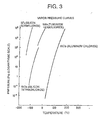
- Fig. 3 shows vapor pressure curves of four kinds of exhaust gases (silicon tetrafluoride, tungsten hexafluoride, silicon tetrachloride, and aluminum chloride). On the right-hand side of each vapor pressure curve, the gas is in a gaseous state, and on the left-hand side thereof, it is in a solid or liquid state. The vapor pressure curves show that each of the four kinds of exhaust gases is changed from the gaseous to the solid or liquid state when the pressure increases.
- exhaust gases silicon tetrafluoride, tungsten hexafluoride, silicon tetrachloride, and aluminum chloride.
- the exhaust gas in the vicinity of the gas inlet 3, the exhaust gas is not easily changed to a solid product since the pump portion is near the high-vacuum side and the pressure in the portion is low, whereas the pressure gradually increases from the uppermost stator blade 5 toward the thread stator 7.
- the thread stator 7 is provided with the sheath heaters 10 in the vacuum pump P of this embodiment, as described above.
- the thread stator 7, which is readily subjected to the adhesion and accumulation of product is directly heated by the sheath heaters 10, whereby it is possible to achieve a reduction in the requisite energy for heating and an improvement in terms of responsiveness in heating operation and controllability.
- the vacuum pump P of this embodiment employs such a structure that the sheath heaters 10 are directly embedded or fitted in the thread stator 7, so that it is possible to increase the input power density per unit length, making it possible to achieve a further improvement in terms of responsiveness in heating operation and controllability. Further, it is also possible to meet the need for a high-temperature heating of 100°C or more, which could not be realized by the conventional band heater, thus making it also possible to increase the heating temperature.
- the vacuum pump P of this embodiment adopts a structure in which the lowermost stator blade 5 and the gas outlet 9 are in direct contact with the thread stator 7, so that the stator blade 5 and the rotor blade 4 in the vicinity of the thread stator 7 and the gas outlet 9 are also heated by thermal conduction, whereby it is possible to effectively prevent the product adhesion to and accumulation in the gas outlet 9, etc.
- the present invention is applicable not only to the structure of the above embodiment, which uses the sheath heaters 10 built in the pump, but also to a structure which has a band heater attached to the outer periphery of the pump case.
- the thread groove 8 of the above embodiment is also possible for the thread groove 8 of the above embodiment to be provided on the rotor 2 side instead of on the thread stator 7 side.
- the thread groove 8 is formed in the outer peripheral surface of the rotor 2 opposed to the thread stator 7.
- bearing means for the rotor shaft 11 of the above embodiment it is also possible to use non-contact type bearings, such as magnetic bearings, instead of the above-described ball bearings 12.
- the vacuum pump according to the present invention adopts an arrangement in which the set temperature of the sheath heaters is determined from a database in memory on the basis of parameters constituting factors determining the rotor temperature, so that it is possible to effectively prevent product adhesion and accumulation inside the pump while appropriately controlling the rotor temperature, whereby it is possible to eliminate breakage of the rotor and rotor blades due to thermal fatigue and pump failure due to product adhesion and accumulation, thereby making it possible to elongate the service life of a vacuum pump of this type.
Landscapes
- Engineering & Computer Science (AREA)
- Mechanical Engineering (AREA)
- General Engineering & Computer Science (AREA)
- Physics & Mathematics (AREA)
- Thermal Sciences (AREA)
- Non-Positive Displacement Air Blowers (AREA)
- Structures Of Non-Positive Displacement Pumps (AREA)
- Control Of Positive-Displacement Air Blowers (AREA)
Abstract
Description
Claims (5)
- A vacuum pump comprising:a pump mechanism portion (A) for discharging gas from a vacuum vessel through rotation of a rotor installed in a pump case;a heater (10) for warming the interior of the pump case;a water-cooling tube (25) for cooling the pump case;a send-out means for sending out a parameter constituting a factor determining the temperature of the rotor;a memory (20) for storing a relationship between the parameter and a set temperature of the heater as a database; andwhen the parameter sent out from the send-out means is input, the set temperature of the heater is determined from the database in the memory based on the input parameter.
- A vacuum pump according to Claim 1, wherein the send-out means obtains and sends out information of pump ambient air temperature as a parameter.
- A vacuum pump according to Claim 1, wherein the send-out means obtains and sends out information of the temperature and flow rate of pump cooling water as a parameter.
- A vacuum pump according to Claim 1, wherein the send-out means obtains and sends out information of the kind and flow rate of pump evacuation gas as a parameter.
- A vacuum pump according to Claim 1, wherein the send-out means obtains and sends out information of pump exhaust pressure as a parameter.
Applications Claiming Priority (2)
| Application Number | Priority Date | Filing Date | Title |
|---|---|---|---|
| JP2000356377A JP2002155891A (en) | 2000-11-22 | 2000-11-22 | Vacuum pump |
| JP2000356377 | 2000-11-22 |
Publications (2)
| Publication Number | Publication Date |
|---|---|
| EP1211424A2 true EP1211424A2 (en) | 2002-06-05 |
| EP1211424A3 EP1211424A3 (en) | 2003-05-14 |
Family
ID=18828638
Family Applications (1)
| Application Number | Title | Priority Date | Filing Date |
|---|---|---|---|
| EP01309808A Withdrawn EP1211424A3 (en) | 2000-11-22 | 2001-11-21 | Vacuum pump |
Country Status (4)
| Country | Link |
|---|---|
| US (1) | US6599108B2 (en) |
| EP (1) | EP1211424A3 (en) |
| JP (1) | JP2002155891A (en) |
| KR (1) | KR20020040603A (en) |
Cited By (4)
| Publication number | Priority date | Publication date | Assignee | Title |
|---|---|---|---|---|
| CN100354589C (en) * | 2003-11-24 | 2007-12-12 | 深圳大学 | Vacuum smelting furnace |
| WO2015043964A1 (en) * | 2013-09-24 | 2015-04-02 | Oerlikon Leybold Vacuum Gmbh | Vacuum pump housing |
| WO2015177514A1 (en) * | 2014-05-19 | 2015-11-26 | Edwards Limited | Vacuum system |
| CN107044435A (en) * | 2016-05-13 | 2017-08-15 | 周卫华 | Determine air quantity intelligent control centrifugal fan |
Families Citing this family (35)
| Publication number | Priority date | Publication date | Assignee | Title |
|---|---|---|---|---|
| DE10142567A1 (en) * | 2001-08-30 | 2003-03-20 | Pfeiffer Vacuum Gmbh | Turbo molecular pump |
| JP4147042B2 (en) * | 2002-03-12 | 2008-09-10 | エドワーズ株式会社 | Vacuum pump |
| DE602004029470D1 (en) * | 2003-08-08 | 2010-11-18 | Edwards Japan Ltd | VACUUM PUMP |
| US7416525B2 (en) * | 2003-09-18 | 2008-08-26 | Myrakelle, Llc | Rotary blood pump |
| US20070020115A1 (en) * | 2005-07-01 | 2007-01-25 | The Boc Group, Inc. | Integrated pump apparatus for semiconductor processing |
| JP4821308B2 (en) * | 2005-12-21 | 2011-11-24 | 株式会社島津製作所 | Vacuum pump |
| JP4899598B2 (en) * | 2006-04-07 | 2012-03-21 | 株式会社島津製作所 | Turbo molecular pump |
| JP4882558B2 (en) * | 2006-07-11 | 2012-02-22 | 株式会社島津製作所 | Turbo molecular pump |
| JP2009103138A (en) * | 2009-02-18 | 2009-05-14 | Shimadzu Corp | Turbo molecular pump |
| JP5218220B2 (en) * | 2009-03-31 | 2013-06-26 | 株式会社島津製作所 | Turbo molecular pump device and control device thereof |
| JP5758303B2 (en) * | 2009-12-11 | 2015-08-05 | エドワーズ株式会社 | Cylindrical fixing member for screw groove exhaust part and vacuum pump using this |
| US9329066B2 (en) * | 2010-03-01 | 2016-05-03 | Provtagaren Ab | Flow regulating system and monitoring device comprising said flow regulating system for the detection of air borne analytes |
| JP5763329B2 (en) * | 2010-11-30 | 2015-08-12 | アルバック機工株式会社 | Pump device and control method thereof |
| US8840380B2 (en) * | 2011-01-21 | 2014-09-23 | Toyota Motor Engineering & Manufacturing North America, Inc. | Temperature control ring for vehicle air pump |
| CN102903399B (en) * | 2011-07-29 | 2015-01-07 | 核工业西南物理研究院 | Multistage differential vacuum pumping system for pellet charging propulsive gas in nuclear fusion |
| DE102011118661A1 (en) * | 2011-11-16 | 2013-05-16 | Pfeiffer Vacuum Gmbh | Friction vacuum pump |
| KR102020693B1 (en) * | 2012-04-24 | 2019-09-10 | 에드워즈 가부시키가이샤 | Deposit detection device for exhaust pump, and exhaust pump |
| JP6077804B2 (en) * | 2012-09-06 | 2017-02-08 | エドワーズ株式会社 | Fixed side member and vacuum pump |
| JP6289148B2 (en) * | 2014-02-14 | 2018-03-07 | エドワーズ株式会社 | Vacuum pump and heat insulating spacer used in the vacuum pump |
| JP6287475B2 (en) * | 2014-03-28 | 2018-03-07 | 株式会社島津製作所 | Vacuum pump |
| JP6453070B2 (en) * | 2014-12-18 | 2019-01-16 | 株式会社荏原製作所 | Dry vacuum pump and dry vacuum pump manufacturing method |
| JP6391171B2 (en) * | 2015-09-07 | 2018-09-19 | 東芝メモリ株式会社 | Semiconductor manufacturing system and operation method thereof |
| US10590955B2 (en) * | 2017-02-23 | 2020-03-17 | Shimadzu Corporation | Turbo-molecular pump |
| JP6943629B2 (en) * | 2017-05-30 | 2021-10-06 | エドワーズ株式会社 | Vacuum pump and its heating device |
| CN107906058B (en) * | 2017-10-31 | 2019-07-23 | 中广核工程有限公司 | A monitoring system and method for preventing cavitation of vacuum pump in nuclear power plant |
| US10655638B2 (en) * | 2018-03-15 | 2020-05-19 | Lam Research Corporation | Turbomolecular pump deposition control and particle management |
| JP7164981B2 (en) * | 2018-07-19 | 2022-11-02 | エドワーズ株式会社 | Vacuum pump |
| JP7481085B2 (en) * | 2018-09-26 | 2024-05-10 | 株式会社荏原製作所 | Gas transfer device and method of using the gas transfer device |
| JP7242321B2 (en) * | 2019-02-01 | 2023-03-20 | エドワーズ株式会社 | Vacuum pump and vacuum pump controller |
| JP7438698B2 (en) * | 2019-09-12 | 2024-02-27 | エドワーズ株式会社 | Vacuum pumps and vacuum pump systems |
| CN112032021B (en) * | 2020-09-10 | 2024-04-26 | 北京通嘉宏瑞科技有限公司 | Temperature control device for vacuum pump and use method thereof |
| JP7533324B2 (en) * | 2021-04-01 | 2024-08-14 | 株式会社島津製作所 | Vacuum pump |
| JP7341200B2 (en) * | 2021-09-24 | 2023-09-08 | 株式会社Kokusai Electric | Systems, processing equipment, semiconductor device manufacturing methods, and programs |
| FR3147334B1 (en) * | 2023-03-30 | 2025-03-14 | Pfeiffer Vacuum | Method for controlling the operating parameters of a turbomolecular vacuum pump |
| CN116591934B (en) * | 2023-04-13 | 2024-11-26 | 北京通嘉宏瑞科技有限公司 | Pump body heating control system and pump body heating control method |
Family Cites Families (8)
| Publication number | Priority date | Publication date | Assignee | Title |
|---|---|---|---|---|
| JPS6419198A (en) * | 1987-07-15 | 1989-01-23 | Hitachi Ltd | Vacuum pump |
| US4926648A (en) * | 1988-03-07 | 1990-05-22 | Toshiba Corp. | Turbomolecular pump and method of operating the same |
| US6022195A (en) * | 1988-09-13 | 2000-02-08 | Helix Technology Corporation | Electronically controlled vacuum pump with control module |
| JP3616639B2 (en) * | 1992-06-19 | 2005-02-02 | ウナクシス ドイチュラント ホールディング ゲゼルシャフト ミット ベシュレンクテル ハフツング | Gas friction vacuum pump |
| DE4410903A1 (en) * | 1994-03-29 | 1995-10-05 | Leybold Ag | System with vacuum pump, measuring device as well as supply, control, operating and display devices |
| DE69625401T2 (en) * | 1995-03-20 | 2003-10-30 | Ebara Corp., Tokio/Tokyo | vacuum pump |
| JP3125207B2 (en) * | 1995-07-07 | 2001-01-15 | 東京エレクトロン株式会社 | Vacuum processing equipment |
| JP3057486B2 (en) * | 1997-01-22 | 2000-06-26 | セイコー精機株式会社 | Turbo molecular pump |
-
2000
- 2000-11-22 JP JP2000356377A patent/JP2002155891A/en not_active Withdrawn
-
2001
- 2001-11-21 US US09/997,482 patent/US6599108B2/en not_active Expired - Fee Related
- 2001-11-21 EP EP01309808A patent/EP1211424A3/en not_active Withdrawn
- 2001-11-22 KR KR1020010072973A patent/KR20020040603A/en not_active Withdrawn
Cited By (5)
| Publication number | Priority date | Publication date | Assignee | Title |
|---|---|---|---|---|
| CN100354589C (en) * | 2003-11-24 | 2007-12-12 | 深圳大学 | Vacuum smelting furnace |
| WO2015043964A1 (en) * | 2013-09-24 | 2015-04-02 | Oerlikon Leybold Vacuum Gmbh | Vacuum pump housing |
| WO2015177514A1 (en) * | 2014-05-19 | 2015-11-26 | Edwards Limited | Vacuum system |
| US10514040B2 (en) | 2014-05-19 | 2019-12-24 | Edwards Limited | Vacuum system |
| CN107044435A (en) * | 2016-05-13 | 2017-08-15 | 周卫华 | Determine air quantity intelligent control centrifugal fan |
Also Published As
| Publication number | Publication date |
|---|---|
| KR20020040603A (en) | 2002-05-30 |
| JP2002155891A (en) | 2002-05-31 |
| US20020090309A1 (en) | 2002-07-11 |
| EP1211424A3 (en) | 2003-05-14 |
| US6599108B2 (en) | 2003-07-29 |
Similar Documents
| Publication | Publication Date | Title |
|---|---|---|
| US6599108B2 (en) | Vacuum pump | |
| US11542950B2 (en) | Vacuum pump | |
| US9618012B2 (en) | Turbo-molecular pump | |
| EP3379086B1 (en) | Vacuum pump | |
| JP3792318B2 (en) | Vacuum pump | |
| CN114270049B (en) | Vacuum pumps and vacuum pump systems | |
| US11466701B2 (en) | Vacuum pump, and stator component, discharge port, and control means used therein | |
| EP4303447A1 (en) | Vacuum pump and vacuum exhaust device | |
| CN110735805A (en) | vacuum pump | |
| US10221863B2 (en) | Vacuum pump | |
| JP2002285992A (en) | Vacuum pump device | |
| JP2006017089A (en) | Temperature control device for turbo molecular pump | |
| JP3084622B2 (en) | Turbo molecular pump | |
| JP4182905B2 (en) | Cold trap and vacuum exhaust | |
| JP7802729B2 (en) | Vacuum pumping system and vacuum pump | |
| JP2004308642A (en) | Cold trap and vacuum pump | |
| JP7668765B2 (en) | Vacuum pump, control device and control method | |
| JP7555227B2 (en) | Vacuum pump and vacuum evacuation system using it | |
| JP2002155890A (en) | Vacuum pump | |
| CN120936810A (en) | Method for controlling the operating parameters of a turbomolecular vacuum pump | |
| JP2001032790A (en) | Turbo molecular pump | |
| JP2002285991A (en) | Turbo molecular pump | |
| JP2001173558A (en) | Evacuation system | |
| JPH03294695A (en) | Molecular turbopump |
Legal Events
| Date | Code | Title | Description |
|---|---|---|---|
| PUAI | Public reference made under article 153(3) epc to a published international application that has entered the european phase |
Free format text: ORIGINAL CODE: 0009012 |
|
| AK | Designated contracting states |
Kind code of ref document: A2 Designated state(s): AT BE CH CY DE DK ES FI FR GB GR IE IT LI LU MC NL PT SE TR |
|
| AX | Request for extension of the european patent |
Free format text: AL;LT;LV;MK;RO;SI |
|
| PUAL | Search report despatched |
Free format text: ORIGINAL CODE: 0009013 |
|
| AK | Designated contracting states |
Designated state(s): AT BE CH CY DE DK ES FI FR GB GR IE IT LI LU MC NL PT SE TR |
|
| AX | Request for extension of the european patent |
Extension state: AL LT LV MK RO SI |
|
| AKX | Designation fees paid | ||
| REG | Reference to a national code |
Ref country code: DE Ref legal event code: 8566 |
|
| STAA | Information on the status of an ep patent application or granted ep patent |
Free format text: STATUS: THE APPLICATION IS DEEMED TO BE WITHDRAWN |
|
| 18D | Application deemed to be withdrawn |
Effective date: 20031115 |