EP1211170A2 - Locking device for a motorcycle, motorcycle with a locking device and a method for controlling a locking device for a motorcycle - Google Patents
Locking device for a motorcycle, motorcycle with a locking device and a method for controlling a locking device for a motorcycle Download PDFInfo
- Publication number
- EP1211170A2 EP1211170A2 EP20010125652 EP01125652A EP1211170A2 EP 1211170 A2 EP1211170 A2 EP 1211170A2 EP 20010125652 EP20010125652 EP 20010125652 EP 01125652 A EP01125652 A EP 01125652A EP 1211170 A2 EP1211170 A2 EP 1211170A2
- Authority
- EP
- European Patent Office
- Prior art keywords
- sound
- motorcycle
- locking device
- remote control
- signal
- Prior art date
- Legal status (The legal status is an assumption and is not a legal conclusion. Google has not performed a legal analysis and makes no representation as to the accuracy of the status listed.)
- Granted
Links
Images


Classifications
-
- B—PERFORMING OPERATIONS; TRANSPORTING
- B62—LAND VEHICLES FOR TRAVELLING OTHERWISE THAN ON RAILS
- B62H—CYCLE STANDS; SUPPORTS OR HOLDERS FOR PARKING OR STORING CYCLES; APPLIANCES PREVENTING OR INDICATING UNAUTHORIZED USE OR THEFT OF CYCLES; LOCKS INTEGRAL WITH CYCLES; DEVICES FOR LEARNING TO RIDE CYCLES
- B62H5/00—Appliances preventing or indicating unauthorised use or theft of cycles; Locks integral with cycles
- B62H5/20—Appliances preventing or indicating unauthorised use or theft of cycles; Locks integral with cycles indicating unauthorised use, e.g. acting on signalling devices
-
- B—PERFORMING OPERATIONS; TRANSPORTING
- B62—LAND VEHICLES FOR TRAVELLING OTHERWISE THAN ON RAILS
- B62J—CYCLE SADDLES OR SEATS; AUXILIARY DEVICES OR ACCESSORIES SPECIALLY ADAPTED TO CYCLES AND NOT OTHERWISE PROVIDED FOR, e.g. ARTICLE CARRIERS OR CYCLE PROTECTORS
- B62J3/00—Acoustic signal devices; Arrangement of such devices on cycles
- B62J3/10—Electrical devices
- B62J3/14—Electrical devices indicating functioning of other devices, e.g. acoustic warnings indicating that lights are switched on
Definitions
- a shutter-type key lock for hiding a keyhole of a key cylinder into which an ignition key for starting an engine is to be inserted under a cover.
- Such a shutter-type key lock automatically locks a rear wheel when the shutter thereof is closed with a hand and is unlocked with an exclusive key for unlocking at the time of riding.
- a handle can be also locked with the shutter-type key lock.
- a small motorcycle such as a scooter has a bag compartment formed under a hingedly openable seat and provided with a seat lock for locking the seat in a closed state.
- the seat lock is automatically locked by closing the seat and unlocked with an exclusive key or an ignition key.
- said method comprises a remote control operation, wherein an unlock signal is generated in accordance with said remote control operation and the sound is generated upon unlocking in accordance with said unlock signal.
- the locking device 4 such as a shutter-type key lock is manually locked by an ordinary way.
- an unlocking signal sent by operating the remote control transmitter 1 is received by the remote control receiver 2.
- the unlocking mechanism 3 is actuated to unlock the locking device 4.
- the on-body flashers 5 are turned on and off as an answer back for informing the sender of the reception of the signal.
- the operation of the anti-theft device such as an immobilizer mounted on the vehicle body is released, thereby allowing a user to ride the vehicle.
- the unlocking signal also actuates the sound source unit 7, which generates a predetermined electronic sound to inform the user (sender) of the release of locking.
- the answer back by the on-body flashers 5 may be omitted.
- the sound source unit 7 comprises a CPU 9 consisting of a switch element connected to a on-board battery 14 and so on, a sound source selecting circuit 13 for selecting a required electronic sound pattern from a plurality of preset electronic sound patterns (signal-reception melodies), a sound source element 10 for generating an electronic sound of the set electronic sound pattern, an amplifying circuit 11 for amplifying the thus generated electronic sound signal, and a loudspeaker 12 for emitting the thus amplified electronic sound signal as a sound.
- the sound source unit 7 is formed as an integral component accommodated in a case or the like and mounted on the vehicle body as described below.
- the user may set the sound for informing the release of the shutter-type key lock 16 (Fig. 4) and the sound for informing the release of the seat lock 18 (Fig. 4) in different electronic sounds from a plurality of predetermined sound sources so that the user can distinguish which lock has been operated.
- the user may input and store such electronic sound patterns in a memory as electronic data and make a selection therefrom.
- the sound source unit 7 shown in Fig. 2 waits an input of an unlocking signal from the remote control transmitter 1 (Fig. 1) (Step 1).
- a signal is inputted (Step 2), whether the signal pattern thereof matches the pattern of the unlocking signal previously stored in the CPU 9 is checked (Step 3). This is for the prevention of maloperation by a disturbing signal or other signals.
- a sound source of an electronic sound pattern previously set in the CPU 9 is selected (Step 4), and an electronic sound is generated and emitted to the outside via the loudspeaker 12 (Fig. 2) (Step 5).
- the electronic sound is stopped after a lapse of a predetermined period of time, and the sound source unit 7 returns to the initial state (Step 6).
- Fig. 4 is a block diagram illustrating the constitution of the locking device for a vehicle with a shutter-type key lock and a seat lock according to embodiment.
- the horn 34 is disposed above the attaching portion of the sound source unit, and the sound emitting port 35 is opened in front thereof.
- the sound emitting port 35 is not opened in a shape of a letter V shown in the drawings but only a portion opposed to the horn 34 is opened, in reality.
- the other portion is a recess formed on design and contributes to improving the appearance and enhancing the strength and waterproof capability.
- the embodiments described above are teaching a method for controlling locking device for a motorcycle with the step of: generating a sound upon unlocking.
Landscapes
- Engineering & Computer Science (AREA)
- Mechanical Engineering (AREA)
- Physics & Mathematics (AREA)
- Acoustics & Sound (AREA)
- Lock And Its Accessories (AREA)
Abstract
Description
- The present invention relates to a locking device for a motorcycle, a motorcycle with a locking device and a method for controlling locking device. In particular it is provided an anti-theft locking device for a motorcycle. The motorcycle herein includes a small motorcycle such as a scooter, a motor driven bicycle such as a 50cc motorcycle and a small two-wheeled vehicle such as a motor-assisted bicycle.
- As a locking device for preventing theft of a motorcycle, there is provided a shutter-type key lock for hiding a keyhole of a key cylinder into which an ignition key for starting an engine is to be inserted under a cover. Such a shutter-type key lock automatically locks a rear wheel when the shutter thereof is closed with a hand and is unlocked with an exclusive key for unlocking at the time of riding. A handle can be also locked with the shutter-type key lock.
- A small motorcycle such as a scooter has a bag compartment formed under a hingedly openable seat and provided with a seat lock for locking the seat in a closed state. The seat lock is automatically locked by closing the seat and unlocked with an exclusive key or an ignition key.
- In order to improve the convenience of the locking device for a motorcycle, a remote control device for a motorcycle which allows unlocking of the lock by remote control operation is designed by the present inventors and under development. The remote control device allows unlocking from a position away from the vehicle body, when an unlocking signal is sent from a transmitter carried by a user to a receiver mounted on a vehicle body. The unlocking signal is inputted to a control unit, whereupon an unlocking mechanism for a shutter-type key lock and a seat lock is actuated.
- In motorcycles, an anti-theft device such as an immobilizer has been put to practical use in addition to such a locking device. The immobilizer, which includes a vibration sensor or a tilt sensor installed in a vehicle body, is actuated to sound an alarm when vibrations or a tilt is detected while a main switch is off. When the shutter-type key lock is unlocked and the main switch is turned on, the operation of the immobilizer is released and the alarm is not sounded. To employ the above-mentioned remote control device, it can be thought that the remote control device may be so constituted that when an unlocking signal is sent from a transmitter to a receiver on a vehicle body, the locking device is unlocked and the operation of the immobilizer is released by the unlocking signal.
- When such a locking device for a motorcycle is provided with an unlocking informing mechanism to permit a user to recognize the release of locking, the convenience thereof is further enhanced. As such an unlocking informing mechanism, there is a thought of turning on and off flasher lamps several times. The blinking of the flash lamps is convenient because the release of locking can be recognized from a position away from the vehicle body when, for example, the locking is released by a remote control operation.
- With the constitution of turning on and off flash lamps, however, there may arise a problem of blinking of the flash lamps during running by maloperation of the remote control. Also, the blinking may be difficult to recognize when the motorcycle is behind other vehicles in a parking lot accommodating a large number of vehicles.
- It is an objective of the present invention to provide a locking device for a motorcycle, a motorcycle with a locking device as well as a method for controlling locking device in which the convenience is improved.
- According to a first aspect of the present invention, said objective is solved by a locking device for a motorcycle, wherein the device comprises a sound source adapted to emit a sound upon unlocking.
- Preferably, said locking device for a motorcycle comprises a remote control receiver for a remote control operation, wherein said sound source is connected to the remote control receiver, and said sound source is provided for emitting a predetermined electronic sound for a predetermined period of time when an unlocking signal is inputted to said remote control receiver.
- Preferably, said sound source comprises a sound source selecting circuit for selecting an electronic sound pattern from a plurality of electronic sound patterns, a sound source element for generating an electronic sound in accordance with the selected electronic sound pattern, an amplifying circuit for amplifying the generated electronic sound signal, and a loudspeaker for emitting the amplified electronic sound signal as the sound.
- Preferably, said locking device for a motorcycle comprises an anti-theft device for controlling a main switch of the motorcycle.
- According to a second aspect of the present invention, the objective mentioned above is solved by a motorcycle with a locking device according to at least one of the
claims 1 to 4, wherein said sound source is mounted on a vehicle body of the motorcycle, and a sound emitting port is opened in a front cover located above a front fender, and said sound source is mounted in the vicinity of said sound emitting port. - Preferably, said motorcycle comprises flasher units, wherein said flasher units are adapted to emit a light signal upon unlocking.
- According to a method aspect of the present invention, the objective mentioned above is solved by a method for controlling locking device for a motorcycle, characterized by generating a sound upon unlocking.
- Preferably, said method comprises a remote control operation, wherein an unlock signal is generated in accordance with said remote control operation and the sound is generated upon unlocking in accordance with said unlock signal.
- Preferably, said method comprises the steps of:
- selecting an electronic sound pattern from a plurality of electronic sound patterns,
- emitting the sound in accordance with the selected electronic sound pattern.
- Preferably, said method further comprises the steps of:
- generating an electronic sound in accordance with the selected electronic sound pattern,
- amplifying the generated electronic sound signal,
- emitting the amplified electronic sound signal as the sound.
- It is an advantage of the present invention, to improve the convenience by providing means for informing a transition from a locked state to an unlocked state.
- Preferred embodiments of the present invention are laid down in the dependent claims.
- In the following, the present invention is explained in greater detail with respect to several embodiments thereof in conjunction with the accompanying drawings, wherein:
- Fig. 1
- is a block diagram illustrating a basic constitution of a locking device according to an embodiment;
- Fig. 2
- is a block diagram of a sound source unit;
- Fig. 3
- is a flowchart illustrating the operation of the sound source unit of the locking device for a motorcycle according to an embodiment;
- Fig. 4
- is a block diagram illustrating the constitution of a locking device with a shutter-type key lock and a seat lock according to an embodiment;
- Fig. 5
- is a side view of a scooter-type motor cycle provided with the locking device for a motorcycle according to an embodiment;
- Fig. 6
- is a side view of the vicinity of an attaching portion of the sound source unit;
- Fig. 7
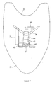
- is a front view of the vicinity of the attaching portion of the sound source unit;
- Fig. 8
- is a top view of the vicinity of the attaching portion of the sound source unit; and
- Fig. 9
- is a detail view of the vicinity of the attaching portion of the sound source unit.
- Fig. 1 is a block diagram illustrating the basic constitution of the lock device for a motorcycle according to an embodiment.
- The embodiment shows a lock device utilizing a remote control device comprising a
remote control transmitter 1 for releasing locking by remote control operation and aremote control receiver 2. Theremote control receiver 2 is mounted on a vehicle body. The vehicle body is provided with alocking device 4 such as a shutter-type key lock for covering a key cylinder (not shown) and anunlocking mechanism 3 thereof. Theremote control receiver 2 is connected to an anti-theft device (immobilizer) 6 and to asound source unit 7 according to the embodiment. In this embodiment, theremote control receiver 2 is also connected to on-body flashers 5, which inform release of unlocking in response to reception of an unlocking signal. The operation of the remote control locking device is as follows. - The
locking device 4 such as a shutter-type key lock is manually locked by an ordinary way. When the locking device is unlocked, an unlocking signal sent by operating theremote control transmitter 1 is received by theremote control receiver 2. Based on the signal, the unlockingmechanism 3 is actuated to unlock thelocking device 4. When the unlocking signal is received, the on-body flashers 5 are turned on and off as an answer back for informing the sender of the reception of the signal. Based on the unlocking signal from theremote control transmitter 1, the operation of the anti-theft device such as an immobilizer mounted on the vehicle body is released, thereby allowing a user to ride the vehicle. In the embodiment, the unlocking signal also actuates thesound source unit 7, which generates a predetermined electronic sound to inform the user (sender) of the release of locking. The answer back by the on-body flashers 5 may be omitted. - Fig. 2 is a block diagram of the above-mentioned sound source unit.
- The
sound source unit 7 comprises aCPU 9 consisting of a switch element connected to a on-board battery 14 and so on, a soundsource selecting circuit 13 for selecting a required electronic sound pattern from a plurality of preset electronic sound patterns (signal-reception melodies), asound source element 10 for generating an electronic sound of the set electronic sound pattern, an amplifyingcircuit 11 for amplifying the thus generated electronic sound signal, and aloudspeaker 12 for emitting the thus amplified electronic sound signal as a sound. Thesound source unit 7 is formed as an integral component accommodated in a case or the like and mounted on the vehicle body as described below. - The operation of the
sound source unit 7 constituted as above is as follows. When an unlocking signal is inputted from the remote control transmitter to the receiver on the vehicle body as described before, for example, the signal is inputted via an interface 8 (I/F) to theCPU 9 and recognized therein. Based on the unlocking signal, theCPU 9 activates thesound source element 10 in accordance with an electronic sound pattern selected with the soundsource selecting circuit 13 to form an electronic sound signal. The electronic sound signal is emitted from theloudspeaker 12 via the amplifyingcircuit 11 toward the outside of the vehicle body, whereby an user who has sent the unlocking signal can recognize with the sound that the unlocking signal has been received by the vehicle body side. - The user may set the sound for informing the release of the shutter-type key lock 16 (Fig. 4) and the sound for informing the release of the seat lock 18 (Fig. 4) in different electronic sounds from a plurality of predetermined sound sources so that the user can distinguish which lock has been operated. The user may input and store such electronic sound patterns in a memory as electronic data and make a selection therefrom.
- To the
CPU 9, thesound source element 10, and the amplifyingcircuit 11 is supplied electric power from the on-board battery 14 via a power source circuit 15. - Fig. 3 is a flowchart illustrating the operation of the sound source unit of the locking device according to an embodiment.
- The
sound source unit 7 shown in Fig. 2 waits an input of an unlocking signal from the remote control transmitter 1 (Fig. 1) (Step 1). When a signal is inputted (Step 2), whether the signal pattern thereof matches the pattern of the unlocking signal previously stored in theCPU 9 is checked (Step 3). This is for the prevention of maloperation by a disturbing signal or other signals. When the signals match with each other, a sound source of an electronic sound pattern previously set in theCPU 9 is selected (Step 4), and an electronic sound is generated and emitted to the outside via the loudspeaker 12 (Fig. 2) (Step 5). The electronic sound is stopped after a lapse of a predetermined period of time, and thesound source unit 7 returns to the initial state (Step 6). - Fig. 4 is a block diagram illustrating the constitution of the locking device for a vehicle with a shutter-type key lock and a seat lock according to embodiment.
- Designated as 16 is a shutter-type key lock (shutter-type anti-theft device) for hiding a keyhole of a key cylinder into which an ignition key for starting an engine is to be inserted with a
shutter 17 and as 18 is a seat lock for locking the seat 19 (see Fig. 5) in a closed state. The shutter-typekey lock 16 and theseat lock 18 are unlocked by an unlockingdevice 20. When theshutter 17 is closed with a hand, the shutter-typekey lock 16 is automatically locked in that state. Theseat lock 18 automatically locks theseat 19 when the seat 19 (Fig. 5) is closed. - The
lock unlocking device 20 is electrically connected to amain body unit 21, which comprises a remote control receiver (not shown) for receiving a signal from theremote control transmitter 1, and a control unit (not shown) for controlling the operation of the unlockingdevice 20 based on the signal received by the receiver. To themain body unit 21, thesound source unit 7 for generating the electronic sound, shown in Fig. 2, abattery 14 and an anti-theft device (immobilizer) 23 are electrically connected. A main switch (ignition switch) 22 is connected to thebattery 14 and theimmobilizer 23. - The
remote control transmitter 1 shown in Fig. 4 is carried by a rider. The other elements are mounted on a body of a motorcycle (Fig. 5). Theremote control transmitter 1 is provided with a shutter-type key lock release button 1a and a seatlock release button 1b. - In the remote control-type locking device having above constitution, when an unlocking signal is sent from the
transmitter 1, the receiver of themain body unit 21 receives the signal. The signal is in turn sent via the control unit to the unlockingdevice 20, which unlocks the shutter-typekey lock 16 and/or theseat lock 18. The unlocking signal also stops the operation of theanti-theft device 23. Moreover, the unlocking signal actuates thesound source unit 7 to make it generate a predetermined electronic sound. - Fig. 5 is a side view of a scooter-type motorcycle provided with the locking device for a motorcycle according to an embodiment.
- As shown in Fig. 5, a
head pipe 24 is located at an upper front part of avehicle body 36 and akey cylinder 33 is disposed beside thehead pipe 24. A steeringshaft 25 rotatably extends through thehead pipe 24. Ahandle 26 is secured to an upper end of the steeringshaft 25 and afront fork 27 is connected to a lower end thereof. Afront wheel 28 is rotatably supported at a lower end part of thefront fork 27. - A down
tube 29, which is bent midway, extends from thehead pipe 24 toward the rear of thevehicle body 36. A pair of right and leftrear frames 30 branching from the rear end of thedown tube 29 are disposed toward the rear of thevehicle body 36. - A portion in the vicinity of the
head pipe 24 is covered with aresin front cover 31, and afront fender 32 is provided at a lower part thereof. Thefront fender 32 is integrally molded with thefront cover 31. Ahorn 34 for generating a klaxon sound is disposed in front of thehead pipe 24 in thefront cover 31. An opening provided in front of thehorn 34 for allowing the sound from thehorn 34 to be well transmitted to the outside forms asound emitting port 35. - The
sound source unit 7 is located in the vicinity of the horn emitting port, below thehorn 34, in thefront cover 31 above thefront fender 32, and disposed such that the electronic sound thereof may be transmitted from thesound emitting port 35 to the outside. - A
seat 19 is provided at an upper rear part of thevehicle body 36. Theseat 19 includes a seat lock 18 (Fig. 4) and becomes rotatable about the front end thereof when theseat lock 18 is unlocked. Astoring box 37 which opens at the top when the seat is rotated is provided under theseat 19 and a fuel tank 39 is disposed in the rear thereof. The main body unit 21 (Fig 4) is disposed in thestoring box 37. The portion under theseat 19 is covered with aside cover 38. On-body flashers 5 are disposed on the right and left sides of a rear part of theside cover 38. On-body flashers 5 are also provided on the right and left sides of a front part of thehandle 26. - An
engine 40 is disposed below thestoring box 37, and a rear wheel 41 is rotatably supported at the rear end thereof. - Fig. 6 is a side view of the vicinity of the attaching portion of the sound source unit, and Fig. 7 and Fig. 8 are a front view and a top view thereof, respectively.
- The
sound source unit 7 connected to the main body unit (Fig. 4) by acable 48 is fixed to asupport stay 44 via a connectingstay 42. One end of thesupport stay 44 is secured to thehead pipe 24. On thesupport stay 44 is mounted electrical equipment 45 (a rectifier regulator, for example). Theelectrical equipment 45 has a flange 46 (Fig. 8), which is fixed to the support stay 44 by abolt 47 screwed into a projection nut 43 (Fig. 7) provided on the lower surface of the support stay. Thebolt 47 not only fixes theelectrical equipment 45 but also integrally fastens the connectingstay 42 under theprojection nut 43 with a nut 52 (Fig. 7). - The
horn 34 is disposed above the attaching portion of the sound source unit, and thesound emitting port 35 is opened in front thereof. Thesound emitting port 35 is not opened in a shape of a letter V shown in the drawings but only a portion opposed to thehorn 34 is opened, in reality. The other portion is a recess formed on design and contributes to improving the appearance and enhancing the strength and waterproof capability. - Fig. 9 is a detail view of the attaching portion of the sound source unit.
- The sound source unit including the
loudspeaker 12 is inserted into a rubbermain body band 49 and supported thereby. Themain body band 49 integrally includes a fixingband 50. Anend 42a of the connectingstay 42 is inserted into the fixingband 50 and fixedly supported thereby. The connectingstay 42 is fixed to the support stay 44 by thebolt 47 as described before. - The embodiments described above are providing a locking device for a motorcycle including a sound source adapted to emit sound upon unlocking.
- With this constitution, since a sound such as an electronic sound is generated by unlocking, release of locking may be recognized, thereby improving the convenience. In the case of a remote control operation, in particular, a user can immediately distinguish its own vehicle with the sound even in a parking lot accommodating a large number of vehicles, for example, thereby further improving the convenience.
- The embodiments mentioned above are teaching a locking device which is actuated by remote control operation, wherein the sound source is connected to a remote control receiver mounted on a vehicle body so that the sound source emits a predetermined electronic sound for a predetermined period of time when an unlocking signal is inputted to the remote control receiver.
- With this constitution, the vehicle body is provided with the receiver and the sound source connected thereto so that the locking is released and an electronic sound is emitted from the sound source to inform the neighborhood of the release of locking by an unlocking signal from a transmitter.
- The locking device for a motorcycle according to the embodiments comprises a
remote control receiver 2 for a remote control operation. Thesound source 7 is connected to theremote control receiver 2, and saidsound source 7 is provided for emitting a predetermined electronic sound for a predetermined period of time when an unlocking signal is inputted to saidremote control receiver 7. - According to an embodiment described above, said
sound source 7 comprises a soundsource selecting circuit 13 for selecting an electronic sound pattern from a plurality of electronic sound patterns, asound source element 10 for generating an electronic sound in accordance with the selected electronic sound pattern, an amplifyingcircuit 11 for amplifying the generated electronic sound signal, and aloudspeaker 12 for emitting the amplified electronic sound signal as the sound. - The locking device for a motorcycle according to the embodiments further comprises an
anti-theft device 23 for controlling amain switch 22 of the motorcycle. - The embodiments described above are teaching a motorcycle with a locking device. The
sound source 7 is mounted on avehicle body 36 of the motorcycle. Asound emitting port 35 is opened in afront cover 31 located above afront fender 32. Saidsound source 7 is mounted in the vicinity of saidsound emitting port 35. - According to said embodiment, a sound emitting port is opened in a front cover located above a front fender, and in that the sound source is mounted in the vicinity of the sound emitting port.
- With this constitution, since the sound source for informing release of locking is disposed in the vicinity of a sound emitting port for a horn opened in the front cover of, for example, a scooter, the sound from the sound source is fully emitted to the outside and thus easy to hear, thereby improving the reconcilability thereof. Also, the sound source is disposed in a relatively high position above a front fender, muddy water or the like from below does not arrive thereat, which is preferable in respect of waterproofing.
- Said motorcycle comprises a locking device and
flasher units 5, wherein saidflasher units 5 are adapted to emit a light signal upon unlocking. - The embodiments described above are teaching a method for controlling locking device for a motorcycle with the step of: generating a sound upon unlocking.
- Said method comprises a remote control operation. An unlock signal is generated in accordance with said remote control operation and the sound is generated upon unlocking in accordance with said unlock signal.
- Said method further comprises the steps of selecting an electronic sound pattern from a plurality of electronic sound patterns, and emitting the sound in accordance with the selected electronic sound pattern.
- Said method further comprises the steps of generating an electronic sound in accordance with the selected electronic sound pattern, amplifying the generated electronic sound signal, and emitting the amplified electronic sound signal as the sound.
- In the embodiments, as described above, a sound such as an electronic sound is generated and emitted to the outside of the vehicle body by unlocking. Therefore, a user can recognized the unlocking, thereby improving the convenience. In the case of remote control operation, in particular, a user can immediately distinguish its own vehicle with the sound from a position away therefrom in a parking lot accommodating a large number of vehicles, thereby further improving the convenience.
Claims (10)
- Locking device for a motorcycle, characterized in that the device comprises a sound source (7) adapted to emit a sound upon unlocking.
- Locking device for a motorcycle according to claim 1, characterized by a remote control receiver (2) for a remote control operation, wherein said sound source (7) is connected to the remote control receiver (2), and said sound source (7) is provided for emitting a predetermined electronic sound for a predetermined period of time when an unlocking signal is inputted to said remote control receiver (7).
- Locking device for a motorcycle according to claim 1 or 2, characterized in that said sound source (7) comprises a sound source selecting circuit (13) for selecting an electronic sound pattern from a plurality of electronic sound patterns, a sound source element (10) for generating an electronic sound in accordance with the selected electronic sound pattern, an amplifying circuit (11) for amplifying the generated electronic sound signal, and a loudspeaker (12) for emitting the amplified electronic sound signal as the sound.
- Locking device for a motorcycle according to at least one of the claims 1 to 3, characterized by an anti-theft device (23) for controlling a main switch (22) of the motorcycle.
- Motorcycle with a locking device according to at least one of the claims 1 to 4, wherein said sound source (7) is mounted on a vehicle body (36) of the motorcycle, and a sound emitting port (35) is opened in a front cover (31) located above a front fender (32), and said sound source (7) is mounted in the vicinity of said sound emitting port (35).
- Motorcycle with a locking device according to claim 5, characterized by flasher units (5), wherein said flasher units (5) are adapted to emit a light signal upon unlocking.
- Method for controlling locking device for a motorcycle, characterized by generating a sound upon unlocking.
- Method for controlling locking device for a motorcycle according to claim 7, characterized by a remote control operation, wherein an unlock signal is generated in accordance with said remote control operation and the sound is generated upon unlocking in accordance with said unlock signal.
- Method for controlling locking device for a motorcycle according to claim 7 or 8, characterized byselecting an electronic sound pattern from a plurality of electronic sound patterns,emitting the sound in accordance with the selected electronic sound pattern.
- Method for controlling locking device for a motorcycle according to claim 9, characterized bygenerating an electronic sound in accordance with the selected electronic sound pattern,amplifying the generated electronic sound signal,emitting the amplified electronic sound signal as the sound.
Applications Claiming Priority (2)
| Application Number | Priority Date | Filing Date | Title |
|---|---|---|---|
| JP2000363931 | 2000-11-30 | ||
| JP2000363931A JP2002168023A (en) | 2000-11-30 | 2000-11-30 | Motorcycle locking device |
Publications (3)
| Publication Number | Publication Date |
|---|---|
| EP1211170A2 true EP1211170A2 (en) | 2002-06-05 |
| EP1211170A3 EP1211170A3 (en) | 2004-12-29 |
| EP1211170B1 EP1211170B1 (en) | 2006-04-12 |
Family
ID=18834960
Family Applications (1)
| Application Number | Title | Priority Date | Filing Date |
|---|---|---|---|
| EP20010125652 Expired - Lifetime EP1211170B1 (en) | 2000-11-30 | 2001-10-26 | Locking device for a motorcycle, motorcycle with a locking device and a method for controlling a locking device for a motorcycle |
Country Status (6)
| Country | Link |
|---|---|
| EP (1) | EP1211170B1 (en) |
| JP (1) | JP2002168023A (en) |
| CN (1) | CN1280149C (en) |
| DE (1) | DE60118693T2 (en) |
| ES (1) | ES2261319T3 (en) |
| TW (1) | TW541256B (en) |
Cited By (8)
| Publication number | Priority date | Publication date | Assignee | Title |
|---|---|---|---|---|
| WO2004028889A1 (en) * | 2002-09-27 | 2004-04-08 | Honda Giken Kogyo Kabushiki Kaisha | Motorcycle electronic key system |
| WO2004031024A1 (en) | 2002-09-30 | 2004-04-15 | Honda Giken Kogyo Kabushiki Kaisha | Vehicle-use electronic key system |
| US7245210B2 (en) | 2002-09-26 | 2007-07-17 | Honda Giken Kogyo Kabushiki Kaisha | Vehicle electronic key system |
| US7279807B2 (en) | 2002-09-27 | 2007-10-09 | Honda Giken Kogyo Kabushiki Kaisha | Vehicle electronic key system |
| EP2447137A1 (en) * | 2010-10-27 | 2012-05-02 | Honda Motor Co., Ltd. | Mounting structure of antitheft device for saddle-type vehicle |
| CN102442266A (en) * | 2010-09-30 | 2012-05-09 | 本田技研工业株式会社 | Vehicle approach notification apparatus for electric motorcycle |
| EP2782081A1 (en) * | 2013-03-22 | 2014-09-24 | Yamaha Hatsudoki Kabushiki Kaisha | Remote control key unit for small vehicle, remote control key system for small vehicle, and small vehicle |
| WO2023139592A1 (en) * | 2022-01-21 | 2023-07-27 | Tvs Motor Company Limited | A telematic unit mounting in a saddle type vehicle |
Families Citing this family (4)
| Publication number | Priority date | Publication date | Assignee | Title |
|---|---|---|---|---|
| JP4243162B2 (en) * | 2003-10-15 | 2009-03-25 | 本田技研工業株式会社 | non-motorized vehicle |
| JP4627991B2 (en) * | 2004-01-05 | 2011-02-09 | 朝日電装株式会社 | Cylinder lock protector |
| CN103303404B (en) * | 2012-03-09 | 2015-09-16 | 光阳工业股份有限公司 | High identification remote control car finding device and method of operation thereof |
| US8994548B2 (en) * | 2013-06-07 | 2015-03-31 | Ford Global Technologies, Llc | Automobile location detector |
Family Cites Families (10)
| Publication number | Priority date | Publication date | Assignee | Title |
|---|---|---|---|---|
| JPH0530377U (en) * | 1991-09-24 | 1993-04-20 | 富士重工業株式会社 | Automotive keyless entry device |
| US5900806A (en) * | 1992-05-22 | 1999-05-04 | Issa; Darrell E. | Alarm sensor multiplexing |
| JPH0692282A (en) * | 1992-09-16 | 1994-04-05 | Suzuki Motor Corp | Engine starting-steering locking device for motorcycle |
| JPH06167154A (en) * | 1992-11-30 | 1994-06-14 | Yamaha Motor Co Ltd | Key input device |
| JP3240020B2 (en) * | 1993-09-16 | 2001-12-17 | 本田技研工業株式会社 | Power supply for electric vehicles |
| JP3470826B2 (en) * | 1994-06-11 | 2003-11-25 | 本田技研工業株式会社 | Vehicle horn |
| US5612669A (en) * | 1995-04-14 | 1997-03-18 | Kenneth E. Flick | Vehicle security system having enhanced false alarm compensation |
| EP0860353A1 (en) * | 1995-12-22 | 1998-08-26 | Sakae Co., Ltd. | Identification device for two-wheeled vehicle |
| JP3362604B2 (en) * | 1996-07-31 | 2003-01-07 | トヨタ自動車株式会社 | Vehicle anti-theft device |
| JP3923175B2 (en) * | 1998-04-28 | 2007-05-30 | 本田技研工業株式会社 | Motorcycle anti-theft device |
-
2000
- 2000-11-30 JP JP2000363931A patent/JP2002168023A/en active Pending
-
2001
- 2001-10-24 TW TW90126275A patent/TW541256B/en not_active IP Right Cessation
- 2001-10-26 ES ES01125652T patent/ES2261319T3/en not_active Expired - Lifetime
- 2001-10-26 EP EP20010125652 patent/EP1211170B1/en not_active Expired - Lifetime
- 2001-10-26 DE DE2001618693 patent/DE60118693T2/en not_active Expired - Lifetime
- 2001-11-30 CN CNB011424907A patent/CN1280149C/en not_active Expired - Fee Related
Non-Patent Citations (1)
| Title |
|---|
| None |
Cited By (18)
| Publication number | Priority date | Publication date | Assignee | Title |
|---|---|---|---|---|
| US7245210B2 (en) | 2002-09-26 | 2007-07-17 | Honda Giken Kogyo Kabushiki Kaisha | Vehicle electronic key system |
| US7279807B2 (en) | 2002-09-27 | 2007-10-09 | Honda Giken Kogyo Kabushiki Kaisha | Vehicle electronic key system |
| CN100423973C (en) * | 2002-09-27 | 2008-10-08 | 本田技研工业株式会社 | Vehicle electronic key system |
| EP1445180A1 (en) * | 2002-09-27 | 2004-08-11 | Honda Giken Kogyo Kabushiki Kaisha | Motorcycle electronic key system |
| US7369035B2 (en) | 2002-09-27 | 2008-05-06 | Honda Giken Kogyo Kabushiki Kaisha | Motorcycle electronic key system |
| EP1445180A4 (en) * | 2002-09-27 | 2006-09-06 | Honda Motor Co Ltd | Motorcycle electronic key system |
| WO2004028889A1 (en) * | 2002-09-27 | 2004-04-08 | Honda Giken Kogyo Kabushiki Kaisha | Motorcycle electronic key system |
| US7304565B2 (en) | 2002-09-30 | 2007-12-04 | Honda Giken Kogyo Kabushiki Kaisha | Vehicle-use electronic key system |
| EP1547912A4 (en) * | 2002-09-30 | 2006-09-06 | Honda Motor Co Ltd | Vehicle-use electronic key system |
| EP1547912A1 (en) * | 2002-09-30 | 2005-06-29 | Honda Giken Kogyo Kabushiki Kaisha | Vehicle-use electronic key system |
| WO2004031024A1 (en) | 2002-09-30 | 2004-04-15 | Honda Giken Kogyo Kabushiki Kaisha | Vehicle-use electronic key system |
| CN102442266A (en) * | 2010-09-30 | 2012-05-09 | 本田技研工业株式会社 | Vehicle approach notification apparatus for electric motorcycle |
| EP2436581A3 (en) * | 2010-09-30 | 2013-04-03 | Honda Motor Co., Ltd. | Vehicle approach notification apparatus for electric motorcycle |
| US8854196B2 (en) | 2010-09-30 | 2014-10-07 | Honda Motor Co., Ltd. | Vehicle approach notification apparatus for electric motorcycle |
| CN102442266B (en) * | 2010-09-30 | 2015-04-08 | 本田技研工业株式会社 | Vehicle approach notification apparatus for electric motorcycle |
| EP2447137A1 (en) * | 2010-10-27 | 2012-05-02 | Honda Motor Co., Ltd. | Mounting structure of antitheft device for saddle-type vehicle |
| EP2782081A1 (en) * | 2013-03-22 | 2014-09-24 | Yamaha Hatsudoki Kabushiki Kaisha | Remote control key unit for small vehicle, remote control key system for small vehicle, and small vehicle |
| WO2023139592A1 (en) * | 2022-01-21 | 2023-07-27 | Tvs Motor Company Limited | A telematic unit mounting in a saddle type vehicle |
Also Published As
| Publication number | Publication date |
|---|---|
| JP2002168023A (en) | 2002-06-11 |
| EP1211170A3 (en) | 2004-12-29 |
| TW541256B (en) | 2003-07-11 |
| CN1356232A (en) | 2002-07-03 |
| CN1280149C (en) | 2006-10-18 |
| DE60118693T2 (en) | 2006-08-31 |
| DE60118693D1 (en) | 2006-05-24 |
| ES2261319T3 (en) | 2006-11-16 |
| EP1211170B1 (en) | 2006-04-12 |
Similar Documents
| Publication | Publication Date | Title |
|---|---|---|
| JP3844231B2 (en) | Motorcycle anti-theft device | |
| US7071819B2 (en) | Remote control lock operation system for vehicles | |
| JP4097132B2 (en) | Anti-theft device for motorcycles | |
| JP4248214B2 (en) | Anti-theft device for motorcycles | |
| EP1211170B1 (en) | Locking device for a motorcycle, motorcycle with a locking device and a method for controlling a locking device for a motorcycle | |
| JP3919004B2 (en) | Anti-theft device for motorcycles | |
| JP2005119421A (en) | Remote control device for scooter type vehicle | |
| US6759828B2 (en) | Remote lock operation apparatus for light vehicle | |
| CA2675353C (en) | Vehicle trunk locking device | |
| JP5614240B2 (en) | Mounting structure for anti-theft device for saddle-ride type vehicles | |
| JP2001187592A (en) | Electrical parts operating device in motorcycle | |
| JP7489654B2 (en) | Electric bicycle locking system and unlocking method, and electric bicycle | |
| JP2001278154A (en) | Remote control device for motorcycle | |
| JP3923284B2 (en) | Remote control lock operation system for motorcycles | |
| JP3886044B2 (en) | Anti-theft device for motorcycles | |
| JP2010001011A (en) | Theft prevention system and transportation equipment | |
| JP3999102B2 (en) | Anti-theft device and vehicle equipped with the anti-theft device | |
| JP2001278142A (en) | Remote control device for motorcycle | |
| JP7190510B2 (en) | straddle-type vehicle | |
| JP2001278155A (en) | Remote control device for motorcycle | |
| JP2002240760A (en) | Remote locking operation device in light vehicle | |
| JP2004114837A (en) | Anti-theft device in motorcycle | |
| JP2000016362A (en) | Antitheft device of bicycle | |
| JPH0534067U (en) | Car anti-theft device |
Legal Events
| Date | Code | Title | Description |
|---|---|---|---|
| PUAI | Public reference made under article 153(3) epc to a published international application that has entered the european phase |
Free format text: ORIGINAL CODE: 0009012 |
|
| AK | Designated contracting states |
Kind code of ref document: A2 Designated state(s): AT BE CH CY DE DK ES FI FR GB GR IE IT LI LU MC NL PT SE TR |
|
| AX | Request for extension of the european patent |
Free format text: AL;LT;LV;MK;RO;SI |
|
| PUAL | Search report despatched |
Free format text: ORIGINAL CODE: 0009013 |
|
| AK | Designated contracting states |
Kind code of ref document: A3 Designated state(s): AT BE CH CY DE DK ES FI FR GB GR IE IT LI LU MC NL PT SE TR |
|
| AX | Request for extension of the european patent |
Extension state: AL LT LV MK RO SI |
|
| 17P | Request for examination filed |
Effective date: 20041130 |
|
| 17Q | First examination report despatched |
Effective date: 20050406 |
|
| AKX | Designation fees paid |
Designated state(s): DE ES FR IT |
|
| GRAP | Despatch of communication of intention to grant a patent |
Free format text: ORIGINAL CODE: EPIDOSNIGR1 |
|
| GRAS | Grant fee paid |
Free format text: ORIGINAL CODE: EPIDOSNIGR3 |
|
| GRAA | (expected) grant |
Free format text: ORIGINAL CODE: 0009210 |
|
| AK | Designated contracting states |
Kind code of ref document: B1 Designated state(s): DE ES FR IT |
|
| PG25 | Lapsed in a contracting state [announced via postgrant information from national office to epo] |
Ref country code: IT Free format text: LAPSE BECAUSE OF FAILURE TO SUBMIT A TRANSLATION OF THE DESCRIPTION OR TO PAY THE FEE WITHIN THE PRESCRIBED TIME-LIMIT;WARNING: LAPSES OF ITALIAN PATENTS WITH EFFECTIVE DATE BEFORE 2007 MAY HAVE OCCURRED AT ANY TIME BEFORE 2007. THE CORRECT EFFECTIVE DATE MAY BE DIFFERENT FROM THE ONE RECORDED. Effective date: 20060412 |
|
| REF | Corresponds to: |
Ref document number: 60118693 Country of ref document: DE Date of ref document: 20060524 Kind code of ref document: P |
|
| REG | Reference to a national code |
Ref country code: ES Ref legal event code: FG2A Ref document number: 2261319 Country of ref document: ES Kind code of ref document: T3 |
|
| ET | Fr: translation filed | ||
| PLBE | No opposition filed within time limit |
Free format text: ORIGINAL CODE: 0009261 |
|
| STAA | Information on the status of an ep patent application or granted ep patent |
Free format text: STATUS: NO OPPOSITION FILED WITHIN TIME LIMIT |
|
| 26N | No opposition filed |
Effective date: 20070115 |
|
| REG | Reference to a national code |
Ref country code: FR Ref legal event code: PLFP Year of fee payment: 15 |
|
| PGFP | Annual fee paid to national office [announced via postgrant information from national office to epo] |
Ref country code: DE Payment date: 20151022 Year of fee payment: 15 Ref country code: IT Payment date: 20151028 Year of fee payment: 15 |
|
| PGFP | Annual fee paid to national office [announced via postgrant information from national office to epo] |
Ref country code: ES Payment date: 20151028 Year of fee payment: 15 Ref country code: FR Payment date: 20151023 Year of fee payment: 15 |
|
| REG | Reference to a national code |
Ref country code: DE Ref legal event code: R119 Ref document number: 60118693 Country of ref document: DE |
|
| REG | Reference to a national code |
Ref country code: FR Ref legal event code: ST Effective date: 20170630 |
|
| PG25 | Lapsed in a contracting state [announced via postgrant information from national office to epo] |
Ref country code: FR Free format text: LAPSE BECAUSE OF NON-PAYMENT OF DUE FEES Effective date: 20161102 Ref country code: DE Free format text: LAPSE BECAUSE OF NON-PAYMENT OF DUE FEES Effective date: 20170503 |
|
| PG25 | Lapsed in a contracting state [announced via postgrant information from national office to epo] |
Ref country code: IT Free format text: LAPSE BECAUSE OF NON-PAYMENT OF DUE FEES Effective date: 20161026 |
|
| PG25 | Lapsed in a contracting state [announced via postgrant information from national office to epo] |
Ref country code: ES Free format text: LAPSE BECAUSE OF FAILURE TO SUBMIT A TRANSLATION OF THE DESCRIPTION OR TO PAY THE FEE WITHIN THE PRESCRIBED TIME-LIMIT Effective date: 20060412 |
|
| REG | Reference to a national code |
Ref country code: ES Ref legal event code: FD2A Effective date: 20181120 |
|
| PG25 | Lapsed in a contracting state [announced via postgrant information from national office to epo] |
Ref country code: ES Free format text: LAPSE BECAUSE OF FAILURE TO SUBMIT A TRANSLATION OF THE DESCRIPTION OR TO PAY THE FEE WITHIN THE PRESCRIBED TIME-LIMIT Effective date: 20161027 |