EP1210991A1 - Tapered body forming method and rolling device - Google Patents
Tapered body forming method and rolling device Download PDFInfo
- Publication number
- EP1210991A1 EP1210991A1 EP00917405A EP00917405A EP1210991A1 EP 1210991 A1 EP1210991 A1 EP 1210991A1 EP 00917405 A EP00917405 A EP 00917405A EP 00917405 A EP00917405 A EP 00917405A EP 1210991 A1 EP1210991 A1 EP 1210991A1
- Authority
- EP
- European Patent Office
- Prior art keywords
- rolls
- rolling
- rolling device
- tapered
- cross
- Prior art date
- Legal status (The legal status is an assumption and is not a legal conclusion. Google has not performed a legal analysis and makes no representation as to the accuracy of the status listed.)
- Withdrawn
Links
Images






Classifications
-
- B—PERFORMING OPERATIONS; TRANSPORTING
- B21—MECHANICAL METAL-WORKING WITHOUT ESSENTIALLY REMOVING MATERIAL; PUNCHING METAL
- B21C—MANUFACTURE OF METAL SHEETS, WIRE, RODS, TUBES, PROFILES OR LIKE SEMI-MANUFACTURED PRODUCTS OTHERWISE THAN BY ROLLING; AUXILIARY OPERATIONS USED IN CONNECTION WITH METAL-WORKING WITHOUT ESSENTIALLY REMOVING MATERIAL
- B21C37/00—Manufacture of metal sheets, rods, wire, tubes, profiles or like semi-manufactured products, not otherwise provided for; Manufacture of tubes of special shape
- B21C37/06—Manufacture of metal sheets, rods, wire, tubes, profiles or like semi-manufactured products, not otherwise provided for; Manufacture of tubes of special shape of tubes or metal hoses; Combined procedures for making tubes, e.g. for making multi-wall tubes
- B21C37/15—Making tubes of special shape; Making tube fittings
- B21C37/16—Making tubes with varying diameter in longitudinal direction
- B21C37/18—Making tubes with varying diameter in longitudinal direction conical tubes
-
- B—PERFORMING OPERATIONS; TRANSPORTING
- B21—MECHANICAL METAL-WORKING WITHOUT ESSENTIALLY REMOVING MATERIAL; PUNCHING METAL
- B21B—ROLLING OF METAL
- B21B13/00—Metal-rolling stands, i.e. an assembly composed of a stand frame, rolls, and accessories
- B21B13/08—Metal-rolling stands, i.e. an assembly composed of a stand frame, rolls, and accessories with differently-directed roll axes, e.g. for the so-called "universal" rolling process
- B21B13/10—Metal-rolling stands, i.e. an assembly composed of a stand frame, rolls, and accessories with differently-directed roll axes, e.g. for the so-called "universal" rolling process all axes being arranged in one plane
- B21B13/103—Metal-rolling stands, i.e. an assembly composed of a stand frame, rolls, and accessories with differently-directed roll axes, e.g. for the so-called "universal" rolling process all axes being arranged in one plane for rolling bars, rods or wire
-
- B—PERFORMING OPERATIONS; TRANSPORTING
- B21—MECHANICAL METAL-WORKING WITHOUT ESSENTIALLY REMOVING MATERIAL; PUNCHING METAL
- B21B—ROLLING OF METAL
- B21B37/00—Control devices or methods specially adapted for metal-rolling mills or the work produced thereby
- B21B37/16—Control of thickness, width, diameter or other transverse dimensions
- B21B37/24—Automatic variation of thickness according to a predetermined program
-
- B—PERFORMING OPERATIONS; TRANSPORTING
- B21—MECHANICAL METAL-WORKING WITHOUT ESSENTIALLY REMOVING MATERIAL; PUNCHING METAL
- B21C—MANUFACTURE OF METAL SHEETS, WIRE, RODS, TUBES, PROFILES OR LIKE SEMI-MANUFACTURED PRODUCTS OTHERWISE THAN BY ROLLING; AUXILIARY OPERATIONS USED IN CONNECTION WITH METAL-WORKING WITHOUT ESSENTIALLY REMOVING MATERIAL
- B21C3/00—Profiling tools for metal drawing; Combinations of dies and mandrels for metal drawing
- B21C3/02—Dies; Selection of material therefor; Cleaning thereof
- B21C3/06—Dies; Selection of material therefor; Cleaning thereof with adjustable section
-
- B—PERFORMING OPERATIONS; TRANSPORTING
- B21—MECHANICAL METAL-WORKING WITHOUT ESSENTIALLY REMOVING MATERIAL; PUNCHING METAL
- B21C—MANUFACTURE OF METAL SHEETS, WIRE, RODS, TUBES, PROFILES OR LIKE SEMI-MANUFACTURED PRODUCTS OTHERWISE THAN BY ROLLING; AUXILIARY OPERATIONS USED IN CONNECTION WITH METAL-WORKING WITHOUT ESSENTIALLY REMOVING MATERIAL
- B21C3/00—Profiling tools for metal drawing; Combinations of dies and mandrels for metal drawing
- B21C3/02—Dies; Selection of material therefor; Cleaning thereof
- B21C3/08—Dies; Selection of material therefor; Cleaning thereof with section defined by rollers, balls, or the like
-
- B—PERFORMING OPERATIONS; TRANSPORTING
- B21—MECHANICAL METAL-WORKING WITHOUT ESSENTIALLY REMOVING MATERIAL; PUNCHING METAL
- B21B—ROLLING OF METAL
- B21B1/00—Metal-rolling methods or mills for making semi-finished products of solid or profiled cross-section; Sequence of operations in milling trains; Layout of rolling-mill plant, e.g. grouping of stands; Succession of passes or of sectional pass alternations
- B21B1/02—Metal-rolling methods or mills for making semi-finished products of solid or profiled cross-section; Sequence of operations in milling trains; Layout of rolling-mill plant, e.g. grouping of stands; Succession of passes or of sectional pass alternations for rolling heavy work, e.g. ingots, slabs, blooms, or billets, in which the cross-sectional form is unimportant ; Rolling combined with forging or pressing
- B21B1/024—Forging or pressing
-
- B—PERFORMING OPERATIONS; TRANSPORTING
- B21—MECHANICAL METAL-WORKING WITHOUT ESSENTIALLY REMOVING MATERIAL; PUNCHING METAL
- B21B—ROLLING OF METAL
- B21B1/00—Metal-rolling methods or mills for making semi-finished products of solid or profiled cross-section; Sequence of operations in milling trains; Layout of rolling-mill plant, e.g. grouping of stands; Succession of passes or of sectional pass alternations
- B21B1/16—Metal-rolling methods or mills for making semi-finished products of solid or profiled cross-section; Sequence of operations in milling trains; Layout of rolling-mill plant, e.g. grouping of stands; Succession of passes or of sectional pass alternations for rolling wire rods, bars, merchant bars, rounds wire or material of like small cross-section
-
- B—PERFORMING OPERATIONS; TRANSPORTING
- B21—MECHANICAL METAL-WORKING WITHOUT ESSENTIALLY REMOVING MATERIAL; PUNCHING METAL
- B21B—ROLLING OF METAL
- B21B1/00—Metal-rolling methods or mills for making semi-finished products of solid or profiled cross-section; Sequence of operations in milling trains; Layout of rolling-mill plant, e.g. grouping of stands; Succession of passes or of sectional pass alternations
- B21B1/16—Metal-rolling methods or mills for making semi-finished products of solid or profiled cross-section; Sequence of operations in milling trains; Layout of rolling-mill plant, e.g. grouping of stands; Succession of passes or of sectional pass alternations for rolling wire rods, bars, merchant bars, rounds wire or material of like small cross-section
- B21B1/18—Metal-rolling methods or mills for making semi-finished products of solid or profiled cross-section; Sequence of operations in milling trains; Layout of rolling-mill plant, e.g. grouping of stands; Succession of passes or of sectional pass alternations for rolling wire rods, bars, merchant bars, rounds wire or material of like small cross-section in a continuous process
-
- B—PERFORMING OPERATIONS; TRANSPORTING
- B21—MECHANICAL METAL-WORKING WITHOUT ESSENTIALLY REMOVING MATERIAL; PUNCHING METAL
- B21B—ROLLING OF METAL
- B21B15/00—Arrangements for performing additional metal-working operations specially combined with or arranged in, or specially adapted for use in connection with, metal-rolling mills
- B21B15/0035—Forging or pressing devices as units
-
- B—PERFORMING OPERATIONS; TRANSPORTING
- B21—MECHANICAL METAL-WORKING WITHOUT ESSENTIALLY REMOVING MATERIAL; PUNCHING METAL
- B21B—ROLLING OF METAL
- B21B13/00—Metal-rolling stands, i.e. an assembly composed of a stand frame, rolls, and accessories
- B21B2013/003—Inactive rolling stands
-
- B—PERFORMING OPERATIONS; TRANSPORTING
- B21—MECHANICAL METAL-WORKING WITHOUT ESSENTIALLY REMOVING MATERIAL; PUNCHING METAL
- B21B—ROLLING OF METAL
- B21B31/00—Rolling stand structures; Mounting, adjusting, or interchanging rolls, roll mountings, or stand frames
- B21B31/16—Adjusting or positioning rolls
- B21B31/20—Adjusting or positioning rolls by moving rolls perpendicularly to roll axis
- B21B31/32—Adjusting or positioning rolls by moving rolls perpendicularly to roll axis by liquid pressure, e.g. hydromechanical adjusting
-
- B—PERFORMING OPERATIONS; TRANSPORTING
- B21—MECHANICAL METAL-WORKING WITHOUT ESSENTIALLY REMOVING MATERIAL; PUNCHING METAL
- B21B—ROLLING OF METAL
- B21B37/00—Control devices or methods specially adapted for metal-rolling mills or the work produced thereby
- B21B37/16—Control of thickness, width, diameter or other transverse dimensions
- B21B37/24—Automatic variation of thickness according to a predetermined program
- B21B37/26—Automatic variation of thickness according to a predetermined program for obtaining one strip having successive lengths of different constant thickness
Definitions
- the present invention relates to a method of forming a tapered body with a continuously tapered circumferential surface, and a rolling device for plastically working a material with rolls.
- a tapered rod is formed by die forging or cutting a material having a cross-section diameter uniform in the axial direction
- a tapered tube is also formed by die forging descried above.
- the rolling clearance in which the material is to be inserted is conventionally formed fixedly, and only a finished product having a cross-section diameter uniform in the axial direction can be obtained.
- the material or composition of the formed tapered rod may vary. Since the reduction ratio of the cross-section area of the material is large, deformation of the material may exceed the deformability of the material, and the formed tapered rod may have cracked. Therefore, with die forging of a material having a cross-section diameter uniform in the axial direction, a tapered rod excellent in characteristics and quality is difficult to form.
- the forging die In die forging, the amount of deformation of the material caused by one stamping operation is small, and accordingly the working speed is low, so a tapered rod is difficult to form within a short period of time. In addition, due to a mechanical load attributed to an increased reduction ratio of the cross-section area of the material and to a thermal load applied by the high-temperature finished product, the forging die tends to degrade easily and has a short service life. Because of these reasons, in die forging of a material with a cross-section diameter uniform in the axial direction, a tapered rod is difficult to form at a low cost.
- an object of the present invention to provide a tapered body forming method which can form a tapered body excellent in characteristics and quality at a low cost, and a rolling device which can be used for the same.
- a tapered body is formed by die forging from a material with a cross-section diameter varying in an axial direction.
- the reduction ratio of the cross-section area of the material during die forging is small. Therefore, the generated heat value during die forging is small, and when a tapered body is formed, its material or composition does not change easily.
- a tapered body is formed, it does not easily crack. As a result, a tapered body excellent in characteristics and quality can be formed.
- the material for die forging is formed by rolling with a working speed higher than that of die forging.
- a tapered body can be formed within a short period of time.
- the mechanical and thermal loads acting on the forging die during die forging are small.
- the forging die does not degrade easily and has a long service life.
- the tapered body can be formed at a low cost.
- the rolling clearance of a plurality of roll groups sequentially arranged in the transfer direction of the material sequentially decreases in the transfer direction
- a press-down mechanism is provided for forming the clearance by moving a plurality of rolls close to each other and for opening the clearance by moving the plurality of rolls away from each other.
- Rolling by the roll groups can be performed and interrupted at an arbitrary time point during transfer of the material. Therefore, the material can be rolled into a finished product with a cross-sectional shape nonuniform in the axial direction.
- the press-down mechanism forms and opens the clearance independently in units of roll groups
- the time intervals and sequence of formation and opening of the clearance which are performed by the roll groups adjacent to each other in the transfer direction of the material can be controlled. Therefore, the material can be rolled into a finished product in which the sequence with which different cross-sectional shapes appear in the axial direction and the duration of one cross-sectional shape in the axial direction are controlled.
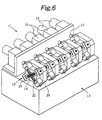
- Fig. 6 shows the entire structure of a rolling device 11 according to this embodiment.
- the rolling device 11 five roll groups 12 are sequentially arranged on a base 13 in the material transfer direction for rolling.
- Each roll group 12 is made up from four rolls 14 having outer peripheral grooves, and an AC servo motor 15 is connected to the rolls 14 of each roll group 12 through reduction gears 16, couplings 17, and the like.
- Figs. 7 and 8 show one roll group 12.
- the rolls 14 and driving gears 21 on the two surfaces of each roll 14 are supported by roll chucks 22 through bearings (not shown), and the roll chucks 22 are accommodated in an X-shaped groove 24 of a frame 23.
- the frame 23 is connected to a gear case 26 through a plurality of bolts 25, and input gears 27 for receiving a driving force from the couplings 17 and transmitting it to the driving gears 21 are arranged in the gear case 26.
- Single acting hydraulic pistons 31 as part of press-down mechanisms for the roll chucks 22 and rolls 14 are attached to the frame 23, and hydraulic pressure supply ports 32 continuous to the hydraulic pistons 31 are connected to a hydraulic circuit (not shown).
- a hydraulic circuit including a hydraulic pump for generating a hydraulic pressure, pipes for distributing the hydraulic pressure from the hydraulic pump to the hydraulic pressure supply ports 32, selector valves arranged between the pipes and the hydraulic pressure supply ports 32, a control means for controlling the selector valves at a predetermined timing with a computer or cam mechanism, and the like can be utilized.
- a circular clearance 33 surrounded by the outer surfaces of the rolls 14 is formed at the center of the four rolls 14, as shown in Fig. 7.
- the material to be rolled is inserted in the clearance 33.
- the clearances 33 of the five roll groups 12 sequentially decrease in the material transfer direction for rolling.
- the input gears 27 are fixed in the gear case 26.
- the positions of the input gears 27 in the gear case 26 are determined such that when the rolls 14 are pressed down, the center-to-center distances between the corresponding driving gears 21 and input gears 27 become minimum. Therefore, when each roll 14 is pressed down, the teeth of either one of the driving gear 21 and input gear 27 do not excessively enter the spaces among the teeth of the other one.
- the frame 23 has cooling oil supply ports 34 through which cooling oil is supplied to the material subjected to rolling in the clearance 33.
- Figs. 1A to 5D show a tapered body forming method according to this embodiment.
- the rolls 14 of the five roll groups 12 sequentially arranged in the material transfer direction for rolling in the rolling device 11 are exemplified as rolls 14a to 14e, and among the four rolls 14 of each roll group 12, only the pair of opposing rolls 14 are shown.
- rolls 14a to 14e need not be pressed down from the beginning as indicated by the solid arrows in Figs. 1A to 1E.
- the rolls 14 can be pressed down by the hydraulic pistons 31 independently in units of roll groups 12, as described above.
- the rolls 14a to 14e may be sequentially pressed down by the hydraulic pistons 31 at least before the material 35 passes them.
- the material 35 is worked into a tapered shape in which the cross-section diameter varies continuously in the axial direction.
- the rolls 14a to 14e only slide on the outer surface of the material 35 and then interrupt rolling of the material 35 temporarily.
- Such intermission and execution of rolling can be performed at an arbitrary time point by the hydraulic pistons 31 controlled by the hydraulic circuit.
- the transfer amount of the material 35 is measured by the amounts of rotation of the rolls 14a to 14e, the amounts of rotation of measurement rolls (not shown) which are arranged before and after the five roll groups 12 and rotate upon coming into contact with the outer surface of the material 35, or the like.
- the portion between the break points 36a and 36b is to be rolled, as rolling with each of the rolls 14a to 14e is to be resumed, if the press-down amounts of the rolls 14a to 14e are gradually increased along with transfer of the material 35, the portion between the break points 36a and 36b is worked into a tapered shape continuously tapered in the direction opposite to the transfer direction of the material 35.
- the material 35 rolled with the rolling device 11 in the above manner is cut by the fly cutter at the exit of the rolling device 11 into a predetermined length, as described above. At this time, if the material 35 is cut at each of the break points 36a and 36b, a material 35a which is tapered in only one direction from one end toward the other end, and is thus suitable for formation of a conical coil spring or the like can be obtained, as shown in Fig. 5A.
- the material 35 is cut at only the break point 36b, a material which is tapered in two directions from the center toward the two ends and is thus suitable for formation of a Barrel-shaped spring or the like can be obtained. At which portion the material 35 is to be cut is appropriately selected in accordance with the kind of finished product for which the material is to be utilized.
- the material 35a is loaded in a forging die 37 with a tapered inner surface, as shown in Fig. 5B.
- the forging die 37 shown in Figs. 5B to 5D is divided only in the vertical direction. If the material 35a is long in the axial direction, a forging die divided not only in the vertical direction but also in the axial direction of the loaded material 35a may be used.
- the material 35a is stamped with the forging die 37, as shown in Fig. 5C, and a tapered finished product 35b is removed from the forging die 37, as shown in Fig. 5D.
- the material 35 is worked alternately into a portion where the material 35 is tapered in the transfer direction of the material 35 and a portion where the material 35 is tapered in a direction opposite to the transfer direction of the material 35.
- the material 35 that is wound in a coiled manner can be worked continuously. Therefore, the characteristic feature of rolling that the working speed is higher than in die forging can be effected.
- the press-down operations for all the rolls 14a to 14e are canceled simultaneously.
- the press-down operations may be sequentially canceled from the rolls 14e toward the rolls 14a. In this case, even if the rolls 14a to 14e are arranged at the same distances from each other as those of the embodiment described above, that portion of the finished material 35 which has a cross-section diameter constant in the axial direction becomes longer than in the above embodiment.
- each roll group 12 is made up from the 4 rolls 14.
- each roll group 12 may be made up from 2 or 3 rolls 14 in accordance with the target cross-sectional shape of the material 35 or the like.
- the hydraulic pistons 31 and the like are used as the press-down mechanisms for the roll chucks 22 and rolls 14.
- feed screws or the like which are controlled by motors may be used as the press-down mechanisms.
- the material 35 is worked with the rolling device 11 in order to form the material 35a which is to be formed into the tapered finished product 35b with the forging die 37.
- the rolling device 11 can naturally be used only for forming the material 35a with a cross-section diameter varying stepwise or continuously in the axial direction into a final finished product.
- the present invention can be utilized for forming a tapered steel rod suitable for forming a Barrel-shaped spring or conical coil spring serving as a coil spring for an automobile suspension system.
Landscapes
- Engineering & Computer Science (AREA)
- Mechanical Engineering (AREA)
- Forging (AREA)
- Metal Rolling (AREA)
- Rolling Contact Bearings (AREA)
Abstract
A rolling device (11) capable of forming and opening a
clearance (33) for rolling, wherein a material (35a) having a
cross-section diameter varying in axial direction is formed,
and a tapered finished product (35b) is formed of the material
(35a) by die forging, whereby a reduction ratio of the cross-sectional
area of the material (35a) formed by die forging is
less than that obtained by forming a material havinga cross-section
diameter uniform in axial direction by die forging
only and, in addition, the finished product (35b) can be
formed in a short time and thus a tapered body excellent in
characteristics and quality can be formed at a low cost.
Description
The present invention relates to a method of
forming a tapered body with a continuously tapered
circumferential surface, and a rolling device for
plastically working a material with rolls.
Conventionally, it is general that a tapered rod
is formed by die forging or cutting a material having a
cross-section diameter uniform in the axial direction, and
that a tapered tube is also formed by die forging descried
above. In a rolling device in which a material is rolled
as it is inserted in a clearance surrounded by the outer
surfaces of a plurality of rolls, the rolling clearance in
which the material is to be inserted is conventionally
formed fixedly, and only a finished product having a
cross-section diameter uniform in the axial direction can
be obtained.
When compared to die forging which is plastic
working, with cutting, the tissue of the material does not
get finer by working, and a finished product with a high
toughness cannot be obtained. The surface smoothness is
low unless polishing or the like is added as a post step.
When a stress is generated in the finished product, it
becomes concentrated in a coarse portion of the surface.
Even if a coil spring is formed of a tapered steel rod, a
coil spring with a sufficiently large fatigue strength
cannot be obtained. In these respects, die forging is
overwhelmingly advantageous to cutting. In addition, in
cutting, the yield is lower than that of die forging
because cutting chips are produced, leading to a high
manufacturing cost of the finished product.
When a tapered rod is formed by die forging of a
material with a cross-section diameter uniform in the axial
direction, the following problems arise. More specifically,
in die forging, heat is generated when the material is
deformed by stamping. Since the cross-section area of the
material has a large reduction ratio, the generated heat
value is also large. If the number of times of stamping
per unit time is increased in order to particularly shorten
the formation time for a tapered rod, sometimes the
finished product reaches a temperature of as high as about
400°C to 500°C.
As a result, the material or composition of the
formed tapered rod may vary. Since the reduction ratio of
the cross-section area of the material is large,
deformation of the material may exceed the deformability of
the material, and the formed tapered rod may have cracked.
Therefore, with die forging of a material having a
cross-section diameter uniform in the axial direction, a
tapered rod excellent in characteristics and quality is
difficult to form.
In die forging, the amount of deformation of the
material caused by one stamping operation is small, and
accordingly the working speed is low, so a tapered rod is
difficult to form within a short period of time. In
addition, due to a mechanical load attributed to an
increased reduction ratio of the cross-section area of the
material and to a thermal load applied by the
high-temperature finished product, the forging die tends to
degrade easily and has a short service life. Because of
these reasons, in die forging of a material with a
cross-section diameter uniform in the axial direction, a
tapered rod is difficult to form at a low cost.
It is, therefore, an object of the present
invention to provide a tapered body forming method which
can form a tapered body excellent in characteristics and
quality at a low cost, and a rolling device which can be
used for the same.
With a tapered body forming method according to
the present invention, a tapered body is formed by die
forging from a material with a cross-section diameter
varying in an axial direction. When compared to a case
wherein a tapered body is to be formed by only die forging
from a material with a cross-section diameter uniform in an
axial direction, the reduction ratio of the cross-section
area of the material during die forging is small.
Therefore, the generated heat value during die forging is
small, and when a tapered body is formed, its material or
composition does not change easily. When a tapered body is
formed, it does not easily crack. As a result, a tapered
body excellent in characteristics and quality can be formed.
The material for die forging is formed by rolling
with a working speed higher than that of die forging. When
compared to a case wherein a tapered body is to be formed
by only die forging from a material with a cross-section
diameter uniform in the axial direction, a tapered body can
be formed within a short period of time. The mechanical
and thermal loads acting on the forging die during die
forging are small. Thus, the forging die does not degrade
easily and has a long service life. As a result, the
tapered body can be formed at a low cost.
In a rolling device according to the present
invention, the rolling clearance of a plurality of roll
groups sequentially arranged in the transfer direction of
the material sequentially decreases in the transfer
direction, and a press-down mechanism is provided for
forming the clearance by moving a plurality of rolls close
to each other and for opening the clearance by moving the
plurality of rolls away from each other. Rolling by the
roll groups can be performed and interrupted at an
arbitrary time point during transfer of the material.
Therefore, the material can be rolled into a finished
product with a cross-sectional shape nonuniform in the
axial direction.
If the press-down mechanism forms and opens the
clearance independently in units of roll groups, the time
intervals and sequence of formation and opening of the
clearance which are performed by the roll groups adjacent
to each other in the transfer direction of the material can
be controlled. Therefore, the material can be rolled into
a finished product in which the sequence with which
different cross-sectional shapes appear in the axial
direction and the duration of one cross-sectional shape in
the axial direction are controlled.
An embodiment of the present invention which is
applied to a tapered body forming method and a rolling
device that can be used for the same will be described
below with reference to Figs. 1A to 8. Fig. 6 shows the
entire structure of a rolling device 11 according to this
embodiment. In the rolling device 11, five roll groups 12
are sequentially arranged on a base 13 in the material
transfer direction for rolling. Each roll group 12 is made
up from four rolls 14 having outer peripheral grooves, and
an AC servo motor 15 is connected to the rolls 14 of each
roll group 12 through reduction gears 16, couplings 17, and
the like.
Figs. 7 and 8 show one roll group 12. In the
roll group 12, the rolls 14 and driving gears 21 on the two
surfaces of each roll 14 are supported by roll chucks 22
through bearings (not shown), and the roll chucks 22 are
accommodated in an X-shaped groove 24 of a frame 23. The
frame 23 is connected to a gear case 26 through a plurality
of bolts 25, and input gears 27 for receiving a driving
force from the couplings 17 and transmitting it to the
driving gears 21 are arranged in the gear case 26.
Single acting hydraulic pistons 31 as part of
press-down mechanisms for the roll chucks 22 and rolls 14
are attached to the frame 23, and hydraulic pressure supply
ports 32 continuous to the hydraulic pistons 31 are
connected to a hydraulic circuit (not shown). As the
hydraulic circuit, a circuit including a hydraulic pump for
generating a hydraulic pressure, pipes for distributing the
hydraulic pressure from the hydraulic pump to the hydraulic
pressure supply ports 32, selector valves arranged between
the pipes and the hydraulic pressure supply ports 32, a
control means for controlling the selector valves at a
predetermined timing with a computer or cam mechanism, and
the like can be utilized.
When the hydraulic pistons 31 press down the roll
chucks 22 and rolls 14 and the four rolls 14 move close to
each other such that their outer surfaces are sequentially
continuous, a circular clearance 33 surrounded by the outer
surfaces of the rolls 14 is formed at the center of the
four rolls 14, as shown in Fig. 7. The material to be
rolled is inserted in the clearance 33. The clearances 33
of the five roll groups 12 sequentially decrease in the
material transfer direction for rolling.
The input gears 27 are fixed in the gear case 26.
The positions of the input gears 27 in the gear case 26 are
determined such that when the rolls 14 are pressed down,
the center-to-center distances between the corresponding
driving gears 21 and input gears 27 become minimum.
Therefore, when each roll 14 is pressed down, the teeth of
either one of the driving gear 21 and input gear 27 do not
excessively enter the spaces among the teeth of the other
one.
When the press-down operations for the roll
chucks 22 and rolls 14 by the hydraulic pistons 31 are
canceled, the rolls 14 move apart from each other, and the
clearance 33 opens by pressing toward the hydraulic pistons
31 with the material inserted into the clearances 33. The
press-down operations for the roll chucks 22 and rolls 14
can be performed and canceled by the hydraulic pistons 31
independently in units of roll groups 12. The frame 23 has
cooling oil supply ports 34 through which cooling oil is
supplied to the material subjected to rolling in the
clearance 33.
Figs. 1A to 5D show a tapered body forming method
according to this embodiment. In Figs. 1A to 4C, the rolls
14 of the five roll groups 12 sequentially arranged in the
material transfer direction for rolling in the rolling
device 11 are exemplified as rolls 14a to 14e, and among
the four rolls 14 of each roll group 12, only the pair of
opposing rolls 14 are shown.
Initially, all the rolls 14a to 14e are pressed
down, as indicated by solid arrows in Figs. 1A to 1E. As a
material 35 is transferred through the rolls 14a to 14e of
the respective roll groups 12, it is rolled such that its
diameter sequentially narrows down, as shown in Figs. 1A to
1E, so the material 35 is worked into a stepped shape in
which the cross-section diameter varies stepwise in the
axial direction. As the material 35, a rod, a pipe, or the
like made of a metal, plastic, ceramic material, or the
like can be used.
Note that all the rolls 14a to 14e need not be
pressed down from the beginning as indicated by the solid
arrows in Figs. 1A to 1E. The rolls 14 can be pressed down
by the hydraulic pistons 31 independently in units of roll
groups 12, as described above. Hence, the rolls 14a to 14e
may be sequentially pressed down by the hydraulic pistons
31 at least before the material 35 passes them.
Since immediately after the rolls 14e start
rolling, if the press-down amounts of all the rolls 14a to
14e are gradually decreased simultaneously along with
transfer of the material 35, the material 35 is worked into
a tapered shape in which the cross-section diameter varies
continuously in the axial direction.
After that, as the material 35 is transferred, as
shown in Fig. 2A, when the leading end of the material 35
has passed the last rolls 14e and is separated from them by
a predetermined distance, that is, when a
predetermined-length portion of the material 35 is rolled
to have the minimum diameter, the press-down operations for
all the rolls 14a to 14e are canceled simultaneously, as
indicated by arrows of alternate long and short dashed
lines in Fig. 2B.
As a result, the rolls 14a to 14e only slide on
the outer surface of the material 35 and then interrupt
rolling of the material 35 temporarily. Such intermission
and execution of rolling can be performed at an arbitrary
time point by the hydraulic pistons 31 controlled by the
hydraulic circuit. The transfer amount of the material 35
is measured by the amounts of rotation of the rolls 14a to
14e, the amounts of rotation of measurement rolls (not
shown) which are arranged before and after the five roll
groups 12 and rotate upon coming into contact with the
outer surface of the material 35, or the like.
After that, as shown in Fig. 2C, when a break
point 36a of the material 35 worked into a stepped shape
has passed the first rolls 14a and is separated from them
by a predetermined distance, only the rolls 14a are pressed
down, and rolling with the rolls 14a is resumed, as shown
in Fig. 2D. A portion of the material 35 which is between
the leading end and the break point 36a is worked into a
stepped shape tapered in the transfer direction of the
material 35. The material 35 is cut at the break point 36a
or a break point formed afterwards by a fly cutter (not
shown) arranged at the exit of the rolling device 11.
As shown in Fig. 2E, when that portion of the
material 35 which is closer to the trailing end side than
the break point 36a and for which rolling with the rolls
14a is resumed first has passed the second rolls 14b and is
separated from them by a predetermined distance, the rolls
14b are pressed down, and rolling with the rolls 14b is
resumed, as shown in Fig. 2F.
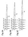
After that, as shown in Figs. 3A to 4C, rolling
with the rolls 14c to 14e is sequentially resumed with the
same operation as that described above. The rolls 14a to
14e in Fig. 4C are in the same state as the rolls 14a to
14e of Fig. 2A. Then, the press-down operations for all
the rolls 14a to 14e are canceled simultaneously, in the
same manner as in Fig. 2B. The portion between the break
point 36a and a break point 36b is worked into a stepped
shape tapered in a direction opposite to the transfer
direction of the material 35.
When the portion between the break points 36a and
36b is to be rolled, as rolling with each of the rolls 14a
to 14e is to be resumed, if the press-down amounts of the
rolls 14a to 14e are gradually increased along with
transfer of the material 35, the portion between the break
points 36a and 36b is worked into a tapered shape
continuously tapered in the direction opposite to the
transfer direction of the material 35.
The material 35 rolled with the rolling device 11
in the above manner is cut by the fly cutter at the exit of
the rolling device 11 into a predetermined length, as
described above. At this time, if the material 35 is cut
at each of the break points 36a and 36b, a material 35a
which is tapered in only one direction from one end toward
the other end, and is thus suitable for formation of a
conical coil spring or the like can be obtained, as shown
in Fig. 5A.
If the material 35 is cut at only the break point
36b, a material which is tapered in two directions from the
center toward the two ends and is thus suitable for
formation of a Barrel-shaped spring or the like can be
obtained. At which portion the material 35 is to be cut is
appropriately selected in accordance with the kind of
finished product for which the material is to be utilized.
Thereafter, in this embodiment, the material 35a
is loaded in a forging die 37 with a tapered inner surface,
as shown in Fig. 5B. The forging die 37 shown in Figs. 5B
to 5D is divided only in the vertical direction. If the
material 35a is long in the axial direction, a forging die
divided not only in the vertical direction but also in the
axial direction of the loaded material 35a may be used.
The material 35a is stamped with the forging die 37, as
shown in Fig. 5C, and a tapered finished product 35b is
removed from the forging die 37, as shown in Fig. 5D.
As is apparent from Figs. 1A to 4C as well, in
the rolling process of this embodiment, the material 35 is
worked alternately into a portion where the material 35 is
tapered in the transfer direction of the material 35 and a
portion where the material 35 is tapered in a direction
opposite to the transfer direction of the material 35.
Hence, the material 35 that is wound in a coiled manner can
be worked continuously. Therefore, the characteristic
feature of rolling that the working speed is higher than in
die forging can be effected.
In the above embodiment, in the step of Fig. 2B,
the press-down operations for all the rolls 14a to 14e are
canceled simultaneously. Alternatively, the press-down
operations may be sequentially canceled from the rolls 14e
toward the rolls 14a. In this case, even if the rolls 14a
to 14e are arranged at the same distances from each other
as those of the embodiment described above, that portion of
the finished material 35 which has a cross-section diameter
constant in the axial direction becomes longer than in the
above embodiment.
Conversely, if the press-down operations are
canceled from the rolls 14a toward the rolls 14e, that
portion of the finished material 35 which has a
cross-section diameter constant in the axial direction
becomes shorter than in the above embodiment. Furthermore,
as the press-down operations for the rolls 14a to 14e are
to be canceled sequentially, when the time intervals of the
canceling operation are not uniform, even if the rolls 14a
to 14e are arranged equidistantly, that portion of the
finished material 35 which has a cross-section diameter
constant in the axial direction does not have a uniform
length.
In the above embodiment, on the base 13, the five
roll groups 12 are sequentially arranged in the transfer
direction of the material 35 for rolling. Alternatively,
roll groups 12 in a necessary number other than 5 may be
sequentially arranged in accordance with the quality, the
target finishing shape, or the like of the material 35. In
the above embodiment, each roll group 12 is made up from
the 4 rolls 14. Alternatively, each roll group 12 may be
made up from 2 or 3 rolls 14 in accordance with the target
cross-sectional shape of the material 35 or the like.
In the above embodiment, the hydraulic pistons 31
and the like are used as the press-down mechanisms for the
roll chucks 22 and rolls 14. Alternatively, feed screws or
the like which are controlled by motors may be used as the
press-down mechanisms. In the above embodiment, the
material 35 is worked with the rolling device 11 in order
to form the material 35a which is to be formed into the
tapered finished product 35b with the forging die 37.
Alternatively, the rolling device 11 can naturally be used
only for forming the material 35a with a cross-section
diameter varying stepwise or continuously in the axial
direction into a final finished product.
For example, the present invention can be
utilized for forming a tapered steel rod suitable for
forming a Barrel-shaped spring or conical coil spring
serving as a coil spring for an automobile suspension
system.
Claims (9)
- A tapered body forming method comprising the steps of:forming a material with a cross-section diameter varying in an axial direction by rolling; andforming a tapered body from the material by die forging.
- A tapered body forming method according to claim 1, in which the material with the cross-section diameter varying stepwise in the axial direction is formed by the rolling.
- A tapered body forming method according to claim 1, in which the material with the cross-section diameter varying continuously in the axial direction is formed by the rolling.
- A rolling device in whicha plurality of rolls are provided to roll a material which is inserted in a clearance surrounded by sequentially continuous outer surfaces of the rolls,a plurality of roll groups each made up from a plurality of rolls are arranged sequentially in a transfer direction of the material for rolling,the clearance of the roll groups sequentially decreases in the transfer direction, anda press-down mechanism is provided for forming the clearance by moving the plurality of rolls close to each other and for opening the clearance by moving the plurality of rolls away from each other.
- A rolling device according to claim 4, wherein the press-down mechanism performs the forming and the opening independently in units of roll groups.
- A rolling device according to claim 5, wherein the press-down mechanism performs the opening simultaneously in all the roll groups.
- A rolling device according to claim 5, wherein the press-down mechanism performs the opening sequentially in units of the roll groups in a direction opposite to the transfer direction.
- A rolling device according to claim 5, wherein the press-down mechanism performs the opening sequentially in units of roll groups in the transfer direction.
- A rolling device according to claim 7 or 8, wherein time intervals in the openings are not uniform.
Applications Claiming Priority (3)
| Application Number | Priority Date | Filing Date | Title |
|---|---|---|---|
| JP11543699 | 1999-04-22 | ||
| JP11543699A JP2003025006A (en) | 1999-04-22 | 1999-04-22 | Method of forming tapered body and rolling device |
| PCT/JP2000/002613 WO2000064604A1 (en) | 1999-04-22 | 2000-04-21 | Tapered body forming method and rolling device |
Publications (2)
| Publication Number | Publication Date |
|---|---|
| EP1210991A1 true EP1210991A1 (en) | 2002-06-05 |
| EP1210991A4 EP1210991A4 (en) | 2005-06-22 |
Family
ID=14662524
Family Applications (1)
| Application Number | Title | Priority Date | Filing Date |
|---|---|---|---|
| EP00917405A Withdrawn EP1210991A4 (en) | 1999-04-22 | 2000-04-21 | PROCESS FOR FORMING CONICAL BODY AND ROLLING DEVICE |
Country Status (3)
| Country | Link |
|---|---|
| EP (1) | EP1210991A4 (en) |
| JP (1) | JP2003025006A (en) |
| WO (1) | WO2000064604A1 (en) |
Cited By (1)
| Publication number | Priority date | Publication date | Assignee | Title |
|---|---|---|---|---|
| CN104646415A (en) * | 2015-01-20 | 2015-05-27 | 广东顺德三扬科技股份有限公司 | Line pressing roller mechanism |
Families Citing this family (2)
| Publication number | Priority date | Publication date | Assignee | Title |
|---|---|---|---|---|
| JP6273393B2 (en) * | 2017-06-07 | 2018-01-31 | 株式会社無有 | Toothpaste manufacturing method |
| JP6276455B2 (en) * | 2017-06-07 | 2018-02-07 | 株式会社無有 | Toothpaste manufacturing method |
Family Cites Families (9)
| Publication number | Priority date | Publication date | Assignee | Title |
|---|---|---|---|---|
| US562825A (en) * | 1896-06-30 | Machinery for manufacturing bicycle-spokes | ||
| JPS4884763A (en) * | 1972-02-16 | 1973-11-10 | ||
| DE2659471A1 (en) * | 1976-12-30 | 1978-07-13 | Peltzer & Ehlers | Forge for cold or hot forming small parts - uses rough rolled material passed through dies and rollers in series |
| US4283930A (en) * | 1977-12-28 | 1981-08-18 | Aichi Steel Works Limited | Roller-dies-processing method and apparatus |
| JPH04111901A (en) * | 1990-08-30 | 1992-04-13 | Mitsubishi Heavy Ind Ltd | Manufacture of parts of tapered extruded shapes |
| JPH079056A (en) * | 1993-06-25 | 1995-01-13 | Morita & Co:Kk | Manufacture of leaf spring |
| JPH09122702A (en) * | 1995-10-31 | 1997-05-13 | Kawasaki Steel Corp | Welding H-shaped steel plate edge forming equipment for web |
| JPH1190510A (en) * | 1997-09-19 | 1999-04-06 | Plant Engineering Yoshida Kinen Kk | Wire rod rolling equipment |
| US6016679A (en) * | 1997-09-30 | 2000-01-25 | Sumitomo Heavy Industries, Ltd. | Rolling mill |
-
1999
- 1999-04-22 JP JP11543699A patent/JP2003025006A/en active Pending
-
2000
- 2000-04-21 WO PCT/JP2000/002613 patent/WO2000064604A1/en not_active Ceased
- 2000-04-21 EP EP00917405A patent/EP1210991A4/en not_active Withdrawn
Cited By (1)
| Publication number | Priority date | Publication date | Assignee | Title |
|---|---|---|---|---|
| CN104646415A (en) * | 2015-01-20 | 2015-05-27 | 广东顺德三扬科技股份有限公司 | Line pressing roller mechanism |
Also Published As
| Publication number | Publication date |
|---|---|
| JP2003025006A (en) | 2003-01-28 |
| WO2000064604A1 (en) | 2000-11-02 |
| EP1210991A4 (en) | 2005-06-22 |
Similar Documents
| Publication | Publication Date | Title |
|---|---|---|
| EP0925857B1 (en) | Method of manufacturing a speed gear | |
| US7866198B2 (en) | Method of producing a stepped shaft | |
| US5325698A (en) | Stepped extrusion die assembly | |
| EP0610509B1 (en) | Method for obtaining hollow forgings by radial forging of continuous blanks | |
| US5040294A (en) | Process for producing a camshaft | |
| EP0913213B1 (en) | Metalworking method | |
| JP2017087250A (en) | Method for manufacturing ring-shaped member | |
| JP7216934B2 (en) | Bearing elements, bearings, machines and vehicles | |
| CN100518989C (en) | Method for production of a seamless hot-finished steel tube and device for carrying out the method | |
| CN113941678B (en) | Forging process for hub sleeve warm forging and cold extrusion and die thereof | |
| WO2002007912A1 (en) | Hydraulic swage press | |
| US6336351B1 (en) | Method of manufacturing spline shaft | |
| WO2000064604A1 (en) | Tapered body forming method and rolling device | |
| EP0678063B1 (en) | Method of manufacturing connecting rods | |
| US20080120846A1 (en) | Apparatus And Method For Manufacturing Outer Race Member For Constant Velocity Joint And Intermediate Molded Body Of The Outer Race Member | |
| JP3697287B2 (en) | Shaft-shaped member processing method | |
| JP4357079B2 (en) | Gear for shifting and manufacturing apparatus therefor | |
| JPWO2000064604A1 (en) | Tapered body forming method and rolling device | |
| JP5195788B2 (en) | Processing method of linear motion guide rail | |
| RU2115532C1 (en) | Hub with flange restoration method | |
| JP3403687B2 (en) | Manufacturing method of multi-stage gear | |
| RU2319559C1 (en) | Wire production method | |
| EP0770438A1 (en) | High production rate swaging machine and swaging working process | |
| EP1114681A1 (en) | Work roll for rolling device | |
| JPH10166097A (en) | Production of different cross-section bar |
Legal Events
| Date | Code | Title | Description |
|---|---|---|---|
| PUAI | Public reference made under article 153(3) epc to a published international application that has entered the european phase |
Free format text: ORIGINAL CODE: 0009012 |
|
| 17P | Request for examination filed |
Effective date: 20011026 |
|
| AK | Designated contracting states |
Kind code of ref document: A1 Designated state(s): AT BE CH CY DE DK ES FI FR GB GR IE IT LI LU MC NL PT SE |
|
| RBV | Designated contracting states (corrected) |
Designated state(s): DE ES FR GB IT |
|
| A4 | Supplementary search report drawn up and despatched |
Effective date: 20050510 |
|
| STAA | Information on the status of an ep patent application or granted ep patent |
Free format text: STATUS: THE APPLICATION IS DEEMED TO BE WITHDRAWN |
|
| 18D | Application deemed to be withdrawn |
Effective date: 20050723 |