EP1210914A1 - Intervertebral fixing system used in treatments of the spinal column - Google Patents
Intervertebral fixing system used in treatments of the spinal column Download PDFInfo
- Publication number
- EP1210914A1 EP1210914A1 EP00951549A EP00951549A EP1210914A1 EP 1210914 A1 EP1210914 A1 EP 1210914A1 EP 00951549 A EP00951549 A EP 00951549A EP 00951549 A EP00951549 A EP 00951549A EP 1210914 A1 EP1210914 A1 EP 1210914A1
- Authority
- EP
- European Patent Office
- Prior art keywords
- screw
- bar
- head
- orifice
- bushing
- Prior art date
- Legal status (The legal status is an assumption and is not a legal conclusion. Google has not performed a legal analysis and makes no representation as to the accuracy of the status listed.)
- Granted
Links
Images


Classifications
-
- A—HUMAN NECESSITIES
- A61—MEDICAL OR VETERINARY SCIENCE; HYGIENE
- A61B—DIAGNOSIS; SURGERY; IDENTIFICATION
- A61B17/00—Surgical instruments, devices or methods, e.g. tourniquets
- A61B17/56—Surgical instruments or methods for treatment of bones or joints; Devices specially adapted therefor
- A61B17/58—Surgical instruments or methods for treatment of bones or joints; Devices specially adapted therefor for osteosynthesis, e.g. bone plates, screws, setting implements or the like
- A61B17/68—Internal fixation devices, including fasteners and spinal fixators, even if a part thereof projects from the skin
- A61B17/70—Spinal positioners or stabilisers ; Bone stabilisers comprising fluid filler in an implant
- A61B17/7001—Screws or hooks combined with longitudinal elements which do not contact vertebrae
- A61B17/7035—Screws or hooks, wherein a rod-clamping part and a bone-anchoring part can pivot relative to each other
- A61B17/7037—Screws or hooks, wherein a rod-clamping part and a bone-anchoring part can pivot relative to each other wherein pivoting is blocked when the rod is clamped
-
- A—HUMAN NECESSITIES
- A61—MEDICAL OR VETERINARY SCIENCE; HYGIENE
- A61B—DIAGNOSIS; SURGERY; IDENTIFICATION
- A61B17/00—Surgical instruments, devices or methods, e.g. tourniquets
- A61B17/56—Surgical instruments or methods for treatment of bones or joints; Devices specially adapted therefor
- A61B17/58—Surgical instruments or methods for treatment of bones or joints; Devices specially adapted therefor for osteosynthesis, e.g. bone plates, screws, setting implements or the like
- A61B17/68—Internal fixation devices, including fasteners and spinal fixators, even if a part thereof projects from the skin
- A61B17/70—Spinal positioners or stabilisers ; Bone stabilisers comprising fluid filler in an implant
- A61B17/7001—Screws or hooks combined with longitudinal elements which do not contact vertebrae
- A61B17/7032—Screws or hooks with U-shaped head or back through which longitudinal rods pass
-
- A—HUMAN NECESSITIES
- A61—MEDICAL OR VETERINARY SCIENCE; HYGIENE
- A61B—DIAGNOSIS; SURGERY; IDENTIFICATION
- A61B17/00—Surgical instruments, devices or methods, e.g. tourniquets
- A61B17/56—Surgical instruments or methods for treatment of bones or joints; Devices specially adapted therefor
- A61B17/58—Surgical instruments or methods for treatment of bones or joints; Devices specially adapted therefor for osteosynthesis, e.g. bone plates, screws, setting implements or the like
- A61B17/68—Internal fixation devices, including fasteners and spinal fixators, even if a part thereof projects from the skin
- A61B17/70—Spinal positioners or stabilisers ; Bone stabilisers comprising fluid filler in an implant
- A61B17/7001—Screws or hooks combined with longitudinal elements which do not contact vertebrae
- A61B17/7041—Screws or hooks combined with longitudinal elements which do not contact vertebrae with single longitudinal rod offset laterally from single row of screws or hooks
Definitions
- the present invention relates to an intervertebral fixation system particularly designed to immobilise two or more vertebrae by using bars which, suitably configured, are attached to the bone by pedicle nails.
- the field of application of the invention is medicine, and particularly bone surgery, allowing to perform equally fixed, mobile fixations or linking plate fixations which laterally displace the area of fixation of the rod with respect to that of the screw.
- a further object of the invention is to associate to said system means of fixation to the sacrum bone, in order to immobilise it with respect to the proximal area of the spinal column, that is, with respect to its lumbar area, in order to attain a tension-free fixation as the sacrum is of a spongier nature than the vertebrae and therefore less resistant.
- One of the systems employed to immobilise two or more bones consists of implanting in these corresponding pedicle screws, each with a head provided with means for attaching to it a bar, which acts as a linking bridge between the various screws, so that as each screw is rigidly connected to the common bar the corresponding bones are thereby immobilised.
- the bar In the fixed system the bar is permanently attached perpendicular to the screw. In the second case between the bar and the screw is provided a knuckle joint which allows to vary the orientation of the bar with respect to the screw. In the third type the bar and screw are related by an intermediate plate which separates them laterally, providing a substantial separation between the aforementioned elements.
- intervertebral fixation system disclosed by the invention which may be used with only slight modifications for both fixed and mobile fixations, as well as for systems requiring a link plate, solves the aforementioned problems in a fully satisfactory manner, allowing implantation of the screw to take place separately from the other parts which are involved with it, that is, in absence of the means of attaching the screw head nail to the screw connecting bar, so that it can be implanted in optimal conditions from the point of view of both handling and visibility.
- the screw involved in the system described in its fixed and mobile versions consists of a functional combination of: a screw having a spherical head which is slightly cambered at its top, meant to be inserted in the bone; an anchor plate which can house the screw head, provided with large recesses for the bar to rest in, and a narrowing mouth having a tronco-conical shape which allows the screw head to pass and causes it to be retained with the aid of an open washer, which is narrowed as it is compressed axially onto the aforementioned tronco-conical mouth; a bushing which acts axially on said open washer and which is pressed in this sense by the bar itself, a second bushing for support and pressure on the opposite area o said bar, and finally a threaded plug which is coupled to the anchor plate mouth and through which is achieved the final fixation and tightening of the assembly.
- Said plug is provided on its lower part with a circular striation.
- the head of the screw is provided with an axial orifice, blind and polygonal, which allows its implantation in the bone with the aid of an Allen wrench, prior to the implantation of the remaining screw mechanisms.
- the bushing which acts on the open washer may incorporate at its end a polygonal prismatic shaped lug for coupling to the blind orifice of the head in a fixed system, or said bushing may have a hemispherical inner surface in order to establish a knuckle joint with the screw head.
- said plate will include a housing similar to that of the anchor plate, but shorter and without recesses, receiving only the bushing which compresses the open washer, which will be threaded, while the bushing proper will be attached to the other end of the linking plate, and receives in it a pseudomorse cone which is used as a means for attaching to the link plate and as a seat for the bar, which will be finally fixed with the aid of a second bushing and a threaded plug as in the previous case.
- Said pseudomorse cone extends as a short cylindrical threaded neck which is implanted in the linking plate, which after the implantation is attached by means of a pin and is integrally joined to the plate.
- a device for transverse union of bars which consists of a piece provided with a recess open on the sides, and suitable in shape and size for a implanting in it the bars to be joined, which recess is crosses by a transverse orifice of the piece itself, which is grooved and meant for implantation of the second bar, this piece further incorporating a threaded orifice which opens perpendicularly from the outside of the transverse orifice and which is meant to receive a tightening plug by which one bar is pressed against the other after their relative position is selected.
- the implantation of the screw is made simple and convenient, with a perfect visibility for the surgeon of the work area, as well as ensuring an ideal structural rigidity for the assembly, that is, a perfect immobilisation of the rod with respect to the screw, without danger of unwanted motion of the cones to be joined, with a minimal effort required of the doctor as well as a minimal time of intervention, and the further possibility of conveniently stiffening with respect to each other of the bars which are part of the system after they are correctly positioned, all of this with the particular characteristic that the multiple parts which participate in the system to achieve fixation of the various elements are supplied to the doctor in a pre-assembled state, suitably connected to each other so that the doctor need only perform the tightening operations after each is correctly placed.
- the open washer which is axially pressed against the truncated conical opening of the anchor plate is absent and the bushing which is axially acting on the washer has a tronco-conical lower area sectioned into segments which can deform upon tightening in order to allow a previous passage of the spherical screw head and to then clip onto said head, so that it remains attached to an joined to the system.
- a complementary element is provided which allows fixation of the corresponding bar relating the sacrum to the lumbar vertebra(e) without any tension whatsoever.
- fixation to the sacrum is based on the use of a template which after fixing the bar to the lumbar area of the spine allows to set the exact point at which the screw must be implanted, as well as its orientation, although the angle of the sacrum screws need not be precise since it must adapt to the screw head to form a knuckle.
- an angular linking plate shaped so that it absorbs the angle formed by the spine where the sacrum meets the lumbar vertebrae, which linking plate is provided at one of its ends with a transverse orifice for coupling of the spinal fixation bar, an orifice which has a toothed inner face to improve grip on the bar, and which is crossed by a threaded orifice for implantation f a tightening screw, preferably with an Allen type head, while on the other end of the clinking plate are established the means of attachment to the screw head.
- Such fixation means comprise a housing with a tronco-conical narrowing opening, through which may pass freely the screw head so that it can be implanted in the bone prior to coupling of the linking plate, establishing inside said housing with a threaded side wall an open washer whose diameter in a relaxed state is greater than both the diameter of the screw head and the diameter of the narrowed opening of the housing, also allowing passage through it of the screw head, this assembly complemented by an externally threaded bushing which is preferably provided with Allen operation means, and the tightening of which causes an axial displacement of the washer with its ensuing strangulation on the screw head and fixation of the latter, with the bushing having a hemispherical housing as a seat for the screw head which allows a knuckle joint movement of these elements prior to the final tightening of the assembly.
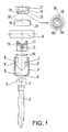
- the intervertebral fixation system for spinal treatments disclosed by the invention comprises a screw (1), to be inserted in the bone, provided with a spherical head (2), provided with an axial blind orifice (3), with a polygonal section, to allow its implantation in the bone with the aid of an Allen wrench.
- Meant to be coupled to head (2) of screw (1) is an anchor plate (4) which is provided at its proximal end with respect to the screw with a tronco-conical narrowing (5), with this narrowing defining an orifice (6) which allows to pass screw head (2), and said anchor plate further incorporating large recesses (7), diametrically aligned, which allow implantation of bar (8), which is the actual piece which joins the vertebrae, as well as an inner threading (9) in the area which frames said recesses (7).
- Anchor plate (4) is meant to receive within it an open washer (10) with a diameter in a relaxed state similar to the inner diameter of the lower sector of anchor plate (4), meant to narrow radially onto the lower area of screw head (2) by axial displacement of a bushing (11), which is basically cylindrical as anchor plate (4), and provided with a circular front for support on washer (10), provided with an axial lug (12), which emerges from its base and couples in blind orifice (3) of screw head (2), and through which these elements are immobilised, and further provided with an upper plate (13) where bar (8) rests.
- a bushing (11) which is basically cylindrical as anchor plate (4), and provided with a circular front for support on washer (10), provided with an axial lug (12), which emerges from its base and couples in blind orifice (3) of screw head (2), and through which these elements are immobilised, and further provided with an upper plate (13) where bar (8) rests.
- plate (13) of bushing (11) is meant to support bar (8) and the axial pressure which is exerted through a second bushing (14) by a threaded plug (15) coupled to threaded opening (9) of the anchor plate (4), which bushing (14) is provided at its base with a threaded orifice (16) which allows it to remain attached to plug (15), which in turn for such purpose is provided with a smooth neck (17) set back with respect to its own threaded sector (18), where bushing (14) is inserted but free.
- Said plug (15) also incorporates an axial, polygonal orifice (19) which can be driven by means of an Allen wrench as that used to implant screw (1).
- Said part (15) is provided on its lower area with a circular striation meant to ensure its grip on bar (8), which is also striated.
- Anchor plate (4) is provided with a pair of lateral recesses (4') which after insertion of part (11) are recut so that said bushing (11) cannot exit nor turn, remaining positioned so that it may properly receive bar (8).
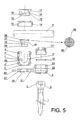
- bushing (11') equivalent to bushing (11) of the previous case, instead of incorporating the latter's axial lug (13) incorporates a hemispherical inner surface (20) with a curvature in accordance to that of screw head (2), thereby establishing a knuckle joint between the two which allows to change the fixed situation of the previous case with bar (8) perpendicular to screw (1), so that the bar may adopt the optimal inclination with respect to the direction of the screw.
- a threaded orifice (24) for attachment to the plate of anchor plate (4"), which here configures a lower housing (25) for a pseudomorse cone (26) with a tronco-conical sector (27) and a threaded neck (28), between which is defined a neck (29) meant to immobilise pseudomorse cone (26) in order to ensure that when it is pressed on by the bar it will form a single rigid body, which will be supplied to the doctor suitably coupled to anchor plate (4"), with the free end of neck (28) riveted to prevent its decoupling from said anchor plate, but allowing a certain mobility so that bar (8) may be suitably directed, with the doctor performing the final fixation with the aid of a set screw (62) which moves in a lateral orifice (61) of plate (21), open towards orifice (24), meant to act on said neck (29) and more specifically to permanently immobilise anchor plate (4") with respect to plate (21), said cone (26) determining the
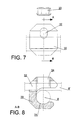
- the system further includes a device for transverse union of the bars, represented in figures 7 and 8, which consists of a part (30) provided with a laterally open, concave, approximately C-shaped housing (31) for coupling and resting of one of bars (8) to be joined, which housing (31) is crossed by a transverse orifice (32), slit in the same sense as housing (31) and meant to receive the second bar (8'), with the final locking of the bars after their correct mutual positioning obtained with a threaded plug (33) which is coupled to an also threaded orifice (34) of part (30) which presses bar (8') against bar (8).
- a device for transverse union of the bars represented in figures 7 and 8, which consists of a part (30) provided with a laterally open, concave, approximately C-shaped housing (31) for coupling and resting of one of bars (8) to be joined, which housing (31) is crossed by a transverse orifice (32), slit in the same sense as housing (31) and meant to receive the second bar (8'
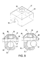
- Figure 9 shows the transverse bar union device finally assembled, which comprises a cap (37) suited in shape and size to be coupled to the top of part (30) in order to prevent the latter from separating from bar (8') and retaining threaded plug (33), so that the transverse union device is mounted before or after its installation on bars (8), considerably simplifying its handling.
- cap (37) is provided on its top base with an orifice (38) through which can be accessed plug (33) so that it may be threaded, and is further provided with respective orifices (39) and (39') for passage of bar (8') through it and through transverse orifice (32).
- Cap (37) keeps together part (30), bar (8') and threaded plug (33), as bar (8') cannot move since it is inserted in said orifices, while cap (37) retains inside it threaded plug (33) but allows its axial displacement with respect to orifice (34) so that it may exert or release the pressure on bar (8).
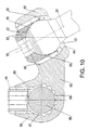
- a method of attachment to the sacrum has been designed and shown in figures 10 and 11, which has as a basic element a linking plate (40) embodied as a part with two end sectors (43) and (44), the first provided with a housing (45) for head (46) of the sacrum implantation screw, and the second provided with an orifice (47) for implantation of the bar (48) meant to relate and attach the sacrum to one or more spinal vertebrae, with the particular characteristic, as seen in figure 9, that the two sectors (43) and (44) of said part form a suitable angle to compensate the angle between the sacrum and the rest of the spine.
- orifice (47) for implantation and fixation of bar (48) which links the linking plate attached to the sacrum to the adjacent area of the spine has an inner surface provided with striations (58) meant to improve the grip on said bar, specifically when it is pressed in its housing by a screw (59) preferably with an Allen type head, which is threaded in an orifice (60) of sector (44) of linking plate (40), which opens perpendicularly towards orifice (47) for implantation of said bar.
- FIGs 12, 13 and 14 show an alternative embodiment for bushing (11) or (11'), when the system is not provided with open washer (10).
- bushing (11a) is conical at its lower area and is divided into sectors (63) which allow deformation of the part when it is tightened and meets conical area (5) of anchor plate (4), which allows entry of spherical head (2) of screw (3), and clips when pressing said bushing (11 a ) against anchor plate (4), making the conical areas clamp spherical head (2) of screw (3), so that the latter is fixed in place and attached to the system.
- bushing (11a) can be used for the fixed system, while bushing (11'a) can be used in the mobile system, in which case it is provided with a central and inner appendix (64), being in all other ways including its function identical to bushing (11a).
- the assembly is delivered assembled, so that its disassembly requires special clamps, first loosening the system and then, through the groove of anchor plate (4) through which the bushing projects slightly, the special clamp is used on the threads, taking care not to move the bushing and lock it when pulling on the screw, thereby allowing exit of the screw.
Abstract
Description
- The present invention relates to an intervertebral fixation system particularly designed to immobilise two or more vertebrae by using bars which, suitably configured, are attached to the bone by pedicle nails.
- The field of application of the invention is medicine, and particularly bone surgery, allowing to perform equally fixed, mobile fixations or linking plate fixations which laterally displace the area of fixation of the rod with respect to that of the screw.
- A further object of the invention is to associate to said system means of fixation to the sacrum bone, in order to immobilise it with respect to the proximal area of the spinal column, that is, with respect to its lumbar area, in order to attain a tension-free fixation as the sacrum is of a spongier nature than the vertebrae and therefore less resistant.
- One of the systems employed to immobilise two or more bones consists of implanting in these corresponding pedicle screws, each with a head provided with means for attaching to it a bar, which acts as a linking bridge between the various screws, so that as each screw is rigidly connected to the common bar the corresponding bones are thereby immobilised.
- Within this bone fixation system exist three types: fixed, mobile and with linking plate.
- In the fixed system the bar is permanently attached perpendicular to the screw. In the second case between the bar and the screw is provided a knuckle joint which allows to vary the orientation of the bar with respect to the screw. In the third type the bar and screw are related by an intermediate plate which separates them laterally, providing a substantial separation between the aforementioned elements.
- The problems presented by this type of fixation mainly stem from the fact that the means for attaching the bar to the screw are from the start already attached to the screw, hindering the implantation of the screw and impairing the view of the surgeon in establishing a proper insertion of the screw in the bone.
- The intervertebral fixation system disclosed by the invention, which may be used with only slight modifications for both fixed and mobile fixations, as well as for systems requiring a link plate, solves the aforementioned problems in a fully satisfactory manner, allowing implantation of the screw to take place separately from the other parts which are involved with it, that is, in absence of the means of attaching the screw head nail to the screw connecting bar, so that it can be implanted in optimal conditions from the point of view of both handling and visibility.
- For this purpose and more specifically, the screw involved in the system described in its fixed and mobile versions, consists of a functional combination of: a screw having a spherical head which is slightly cambered at its top, meant to be inserted in the bone; an anchor plate which can house the screw head, provided with large recesses for the bar to rest in, and a narrowing mouth having a tronco-conical shape which allows the screw head to pass and causes it to be retained with the aid of an open washer, which is narrowed as it is compressed axially onto the aforementioned tronco-conical mouth; a bushing which acts axially on said open washer and which is pressed in this sense by the bar itself, a second bushing for support and pressure on the opposite area o said bar, and finally a threaded plug which is coupled to the anchor plate mouth and through which is achieved the final fixation and tightening of the assembly. Said plug is provided on its lower part with a circular striation.
- According to a further characteristic of the invention the head of the screw is provided with an axial orifice, blind and polygonal, which allows its implantation in the bone with the aid of an Allen wrench, prior to the implantation of the remaining screw mechanisms.
- From this basic structure the bushing which acts on the open washer may incorporate at its end a polygonal prismatic shaped lug for coupling to the blind orifice of the head in a fixed system, or said bushing may have a hemispherical inner surface in order to establish a knuckle joint with the screw head.
- If a linking plate system is used, said plate will include a housing similar to that of the anchor plate, but shorter and without recesses, receiving only the bushing which compresses the open washer, which will be threaded, while the bushing proper will be attached to the other end of the linking plate, and receives in it a pseudomorse cone which is used as a means for attaching to the link plate and as a seat for the bar, which will be finally fixed with the aid of a second bushing and a threaded plug as in the previous case.
- Said pseudomorse cone extends as a short cylindrical threaded neck which is implanted in the linking plate, which after the implantation is attached by means of a pin and is integrally joined to the plate.
- With the above described structure aids a device for transverse union of bars, which consists of a piece provided with a recess open on the sides, and suitable in shape and size for a implanting in it the bars to be joined, which recess is crosses by a transverse orifice of the piece itself, which is grooved and meant for implantation of the second bar, this piece further incorporating a threaded orifice which opens perpendicularly from the outside of the transverse orifice and which is meant to receive a tightening plug by which one bar is pressed against the other after their relative position is selected.
- In accordance with the described structure the implantation of the screw is made simple and convenient, with a perfect visibility for the surgeon of the work area, as well as ensuring an ideal structural rigidity for the assembly, that is, a perfect immobilisation of the rod with respect to the screw, without danger of unwanted motion of the cones to be joined, with a minimal effort required of the doctor as well as a minimal time of intervention, and the further possibility of conveniently stiffening with respect to each other of the bars which are part of the system after they are correctly positioned, all of this with the particular characteristic that the multiple parts which participate in the system to achieve fixation of the various elements are supplied to the doctor in a pre-assembled state, suitably connected to each other so that the doctor need only perform the tightening operations after each is correctly placed.
- In an alternative embodiment, the open washer which is axially pressed against the truncated conical opening of the anchor plate is absent and the bushing which is axially acting on the washer has a tronco-conical lower area sectioned into segments which can deform upon tightening in order to allow a previous passage of the spherical screw head and to then clip onto said head, so that it remains attached to an joined to the system.
- Additionally, a complementary element is provided which allows fixation of the corresponding bar relating the sacrum to the lumbar vertebra(e) without any tension whatsoever.
- More specifically, fixation to the sacrum is based on the use of a template which after fixing the bar to the lumbar area of the spine allows to set the exact point at which the screw must be implanted, as well as its orientation, although the angle of the sacrum screws need not be precise since it must adapt to the screw head to form a knuckle. For this is used an angular linking plate, shaped so that it absorbs the angle formed by the spine where the sacrum meets the lumbar vertebrae, which linking plate is provided at one of its ends with a transverse orifice for coupling of the spinal fixation bar, an orifice which has a toothed inner face to improve grip on the bar, and which is crossed by a threaded orifice for implantation f a tightening screw, preferably with an Allen type head, while on the other end of the clinking plate are established the means of attachment to the screw head.
- Such fixation means comprise a housing with a tronco-conical narrowing opening, through which may pass freely the screw head so that it can be implanted in the bone prior to coupling of the linking plate, establishing inside said housing with a threaded side wall an open washer whose diameter in a relaxed state is greater than both the diameter of the screw head and the diameter of the narrowed opening of the housing, also allowing passage through it of the screw head, this assembly complemented by an externally threaded bushing which is preferably provided with Allen operation means, and the tightening of which causes an axial displacement of the washer with its ensuing strangulation on the screw head and fixation of the latter, with the bushing having a hemispherical housing as a seat for the screw head which allows a knuckle joint movement of these elements prior to the final tightening of the assembly.
- The particular configuration of the linking plate and the fixation means to both the screw head and the bar linking it to the rest of the spine make this fixation free of tensions which may damage the sacrum in the area of implantation of the screw.
- The characteristics of the present invention will be better understood in view of the accompanying drawings made of a preferred embodiment of the invention, where for purposes of illustration only and as an integral part of the description the following is shown:
- Figure 1.- Shows a perspective exploded view of an intervertebral fixation system for spinal treatments in accordance with the present invention, in which some of its elements are shown in a diametric cross section, according to a first embodiment where a fixed system is taught.
- Figure 2.- Shows the same assembly of the previous figure duly assembled and in cross section.
- Figures 3 and 4.- Show similar representations to figures 1 and 2 corresponding here to the mobile system embodiment.
- Figures 5 and 6.- Shows representations also similar to those of figures 1 and 2 here corresponding to the system which uses a linking plate.
- Figure 7.- Shows a side elevation view of the device meant for transverse union of bars which is also part of the system of the invention.
- Figure 8.- Shows a detail of a transverse section of the device of the previous figure along the A-B line of said figure.
- Figure 9.- Shows the transverse union device fully assembled together with the element which keeps all components united, which is shown in an independent perspective view.
- Figure 10.- Shows a side elevation and sectional view of the linking plate which participates in the fixation system to the sacrum bone, on which are coupled the screw head and the bar which bypasses and stiffens the sacrum to other vertebra(e) of the spine.
- Figure 11.- Shows a plan view of said linking plate of the previous figure, here lacking the screw fixing it to the sacrum and the bar, as well as the latter's tightening screw.
- Figure 12.- Shows a side elevation view of the bushing which presses and holds the screw head in an alternative embodiment for a mobile system.
- Figure 13.- Shows a side elevation and sectional view of the bushing of the previous figure for a fixed system.
- Figure 14.- Shows the assembly of the bushing of figure 12 onto the corresponding anchor plate which is part of the system object of the invention.
-
- In view of these figures, and more specifically of figures 1 and 2, the intervertebral fixation system for spinal treatments disclosed by the invention comprises a screw (1), to be inserted in the bone, provided with a spherical head (2), provided with an axial blind orifice (3), with a polygonal section, to allow its implantation in the bone with the aid of an Allen wrench. Meant to be coupled to head (2) of screw (1) is an anchor plate (4) which is provided at its proximal end with respect to the screw with a tronco-conical narrowing (5), with this narrowing defining an orifice (6) which allows to pass screw head (2), and said anchor plate further incorporating large recesses (7), diametrically aligned, which allow implantation of bar (8), which is the actual piece which joins the vertebrae, as well as an inner threading (9) in the area which frames said recesses (7).
- Anchor plate (4), is meant to receive within it an open washer (10) with a diameter in a relaxed state similar to the inner diameter of the lower sector of anchor plate (4), meant to narrow radially onto the lower area of screw head (2) by axial displacement of a bushing (11), which is basically cylindrical as anchor plate (4), and provided with a circular front for support on washer (10), provided with an axial lug (12), which emerges from its base and couples in blind orifice (3) of screw head (2), and through which these elements are immobilised, and further provided with an upper plate (13) where bar (8) rests.
- Thus, plate (13) of bushing (11) is meant to support bar (8) and the axial pressure which is exerted through a second bushing (14) by a threaded plug (15) coupled to threaded opening (9) of the anchor plate (4), which bushing (14) is provided at its base with a threaded orifice (16) which allows it to remain attached to plug (15), which in turn for such purpose is provided with a smooth neck (17) set back with respect to its own threaded sector (18), where bushing (14) is inserted but free. Said plug (15) also incorporates an axial, polygonal orifice (19) which can be driven by means of an Allen wrench as that used to implant screw (1). Said part (15) is provided on its lower area with a circular striation meant to ensure its grip on bar (8), which is also striated.
- Anchor plate (4) is provided with a pair of lateral recesses (4') which after insertion of part (11) are recut so that said bushing (11) cannot exit nor turn, remaining positioned so that it may properly receive bar (8).
- The above described structure is essentially repeated for a mobile fixation system, except that here bushing (11'), equivalent to bushing (11) of the previous case, instead of incorporating the latter's axial lug (13) incorporates a hemispherical inner surface (20) with a curvature in accordance to that of screw head (2), thereby establishing a knuckle joint between the two which allows to change the fixed situation of the previous case with bar (8) perpendicular to screw (1), so that the bar may adopt the optimal inclination with respect to the direction of the screw.
- In addition and as represented in figures 5 and 6, when the system incorporates a linking plate (21) this shall be provided with a housing (22) similar to the lower sector of anchor plate (4) of the previous cases, with the same narrowing tronco-conical opening (5) and equally provided with a threading (23) for coupling of a bushing (11"), also similar to bushing (11) of the fixed system with the same axial lug (12) but with an external thread for implantation in berth (22) of plate (21), and more specifically for axial pressure on open washer (10), causing it to strangle on head (2) of screw (1).
- In a different sector of lining plate (21) is provided a threaded orifice (24) for attachment to the plate of anchor plate (4"), which here configures a lower housing (25) for a pseudomorse cone (26) with a tronco-conical sector (27) and a threaded neck (28), between which is defined a neck (29) meant to immobilise pseudomorse cone (26) in order to ensure that when it is pressed on by the bar it will form a single rigid body, which will be supplied to the doctor suitably coupled to anchor plate (4"), with the free end of neck (28) riveted to prevent its decoupling from said anchor plate, but allowing a certain mobility so that bar (8) may be suitably directed, with the doctor performing the final fixation with the aid of a set screw (62) which moves in a lateral orifice (61) of plate (21), open towards orifice (24), meant to act on said neck (29) and more specifically to permanently immobilise anchor plate (4") with respect to plate (21), said cone (26) determining the seat for bar (8) which is similarly attached with the aid of bushing (14) and threaded plug (15) in sector (8) of said anchor plate (4').
- In addition to the described structure the system further includes a device for transverse union of the bars, represented in figures 7 and 8, which consists of a part (30) provided with a laterally open, concave, approximately C-shaped housing (31) for coupling and resting of one of bars (8) to be joined, which housing (31) is crossed by a transverse orifice (32), slit in the same sense as housing (31) and meant to receive the second bar (8'), with the final locking of the bars after their correct mutual positioning obtained with a threaded plug (33) which is coupled to an also threaded orifice (34) of part (30) which presses bar (8') against bar (8).
- Figure 9 shows the transverse bar union device finally assembled, which comprises a cap (37) suited in shape and size to be coupled to the top of part (30) in order to prevent the latter from separating from bar (8') and retaining threaded plug (33), so that the transverse union device is mounted before or after its installation on bars (8), considerably simplifying its handling.
- For this purpose cap (37) is provided on its top base with an orifice (38) through which can be accessed plug (33) so that it may be threaded, and is further provided with respective orifices (39) and (39') for passage of bar (8') through it and through transverse orifice (32). Cap (37) keeps together part (30), bar (8') and threaded plug (33), as bar (8') cannot move since it is inserted in said orifices, while cap (37) retains inside it threaded plug (33) but allows its axial displacement with respect to orifice (34) so that it may exert or release the pressure on bar (8).
- To prevent part (30) and the elements joined to it from being removed through the ends of bar (8'), these ends are expanded or oversized, or any element which increases their diameter is added, characteristic which has not bee represented in the figures.
- It only remains to point out that head (2) of screw (1) has striations to ensure stability of the assembly after it is tightened, and that bar (8) has a striated surface for the same purpose of providing a proper stability after it is fixed.
- In addition to the described system, a method of attachment to the sacrum has been designed and shown in figures 10 and 11, which has as a basic element a linking plate (40) embodied as a part with two end sectors (43) and (44), the first provided with a housing (45) for head (46) of the sacrum implantation screw, and the second provided with an orifice (47) for implantation of the bar (48) meant to relate and attach the sacrum to one or more spinal vertebrae, with the particular characteristic, as seen in figure 9, that the two sectors (43) and (44) of said part form a suitable angle to compensate the angle between the sacrum and the rest of the spine.
- Housing (45) for screw head (46), basically cylindrical, has a tronco-conical narrowing (49) at the end where it meets the sacrum, and a threaded sector (50) on the opposite end, with opening (51) defined by said tronco-conical narrowing (49) having a diameter greater than that of the spherical screw head (46) in order to allow the implantation of said screw in the sacrum prior to assembly on it of liking plate (40), with the truncated cone plane of narrowing (49) specifically meant to strangle an open washer (52) which rests on it, which when relaxed also has a diameter greater than that of the screw head (46) so that said head may pass through it, and which is axially displaced with the aid of a bushing (53), interiorly defining a cambered hemispherical housing (54) to allow a knuckle movement of head (46) of the screw, and which is provided with an external thread for attachment to threaded sector (50) of housing (45), and is further provided on its base with a polygonal orifice (55) for driving with an Allen wrench, all such that after screw head (46) is implanted in housing (45) and after the linking plate (40) is properly orientated with respect to axis (56) of said screw, the pressure applied by bushing (53) causes an axial displacement of washer (52) and its strangulation on the neck of the screw with the ensuing locking of the assembly, which locking is favoured by the presence of annular teeth (57) on screw head (46) which bite into the surface of housing (54) of bushing (53).
- Furthermore, orifice (47) for implantation and fixation of bar (48) which links the linking plate attached to the sacrum to the adjacent area of the spine, has an inner surface provided with striations (58) meant to improve the grip on said bar, specifically when it is pressed in its housing by a screw (59) preferably with an Allen type head, which is threaded in an orifice (60) of sector (44) of linking plate (40), which opens perpendicularly towards orifice (47) for implantation of said bar.
- Figures 12, 13 and 14 show an alternative embodiment for bushing (11) or (11'), when the system is not provided with open washer (10).
- Specifically, in this case bushing (11a) is conical at its lower area and is divided into sectors (63) which allow deformation of the part when it is tightened and meets conical area (5) of anchor plate (4), which allows entry of spherical head (2) of screw (3), and clips when pressing said bushing (11a) against anchor plate (4), making the conical areas clamp spherical head (2) of screw (3), so that the latter is fixed in place and attached to the system.
- As described above bushing (11a) can be used for the fixed system, while bushing (11'a) can be used in the mobile system, in which case it is provided with a central and inner appendix (64), being in all other ways including its function identical to bushing (11a).
- The assembly is delivered assembled, so that its disassembly requires special clamps, first loosening the system and then, through the groove of anchor plate (4) through which the bushing projects slightly, the special clamp is used on the threads, taking care not to move the bushing and lock it when pulling on the screw, thereby allowing exit of the screw.
Claims (16)
- Intervertebral fixation system for spinal treatments, which includes pedicle screws (1) having a spherical head (2) provided with a blind axial orifice (3) with a polygonal section, said screws (1) to be implanted in the bone, to which are attached bars acting as a linking means between the various screws for relative immobilisation of the corresponding bones, fixation system this which may be fixed or mobile, and including a complement for fixation of the sacrum, characterised in that the spherical head (2) of the screw (1) is aided by an anchor plate (4) which in its area proximal to screw (1) is provided with a tronco-conical narrowing opening (5) which defines an orifice (6) with a diameter greater than that of screw head (2), and with said anchor plate (4) designed to house within it a bushing (11) on which rests bar (8) to be fixed, , with an additional bushing (14) acting on the external area corresponding to bar (8), and axially pressed by a plug (15) which is threaded onto the also threaded opening (9) of anchor plate (4), which is provided with lateral recesses (4') to prevent separation or rotation of bushing (11) after it is inserted in anchor plate (4).
- Intervertebral fixation system for spinal treatments, as claimed in claim 1, characterised in that for a fixed system bushing (11) includes an inner lug (12) emerging axially from its base, with a section having the same configuration as blind orifice (3) of screw head (2) for the relative immobilisation of these two elements.
- Intervertebral fixation system for spinal treatments, as claimed in claim 1, characterised in that for a mobile fixation system bushing (11') has a concave inner surface (20) with a hemispherical shape, defining a knuckle type joint with head (2) of screw (1).
- Intervertebral fixation system for spinal treatments, as claimed in previous claims, characterised in that the anchor plate (4) houses within it an open washer (10) so that the axial displacement of the bushing (11) causes a strangulation of the washer (10) on the lower area of screw head (2) and the ensuing locking of the latter onto the anchor plate (4).
- Intervertebral fixation system for spinal treatments, which includes pedicle screws (1) having a spherical head (2) provided with a blind axial orifice (3) with a polygonal section, said screws (1) to be implanted in the bone, to which are attached bars acting as a linking means between the various screws for relative immobilisation of the corresponding bone, fixation system which is aided by a linking plate characterised in that the linking plate (21) includes on one of its ends a housing (22) which in is area proximal to screw (1) is provided with a tronco-conical narrowing opening (5), with an inner threading (23) for receiving bushing (11"), which is in turn provided with an external threading and which acts as a strangulation means of open washer (10) onto the screw head, while on the other end of the linking plate (21) is defined a threaded orifice (24) for fixation of an anchor plate (4"), here provided with a tronco-conical housing (25) for a pseudomorse cone (26), provided with a threaded neck (28) for fixation to orifice (24) and on which rests bar (8), which is also fixed with the aid of an upper bushing (14) and the complementary plug (15) for axial tightening.
- Intervertebral fixation system for spinal treatments, as claimed in claim 5, characterised in that between tronco-conical sector (27) and cylindrical threaded sector (28) of pseudomorse cone (26) is provided a perimetral neck (29) which after assembly of said cone (26) on the threaded orifice (24) of linking plate (21) is facing an also threaded lateral orifice (61) of plate (21), in which lies a pin (62) which permanently immobilises cone (26) and anchor plate (4") with respect to base plate (21).
- Intervertebral fixation system for spinal treatments, as claimed in previous claims, characterised in that the lower part of plug (15) is striated to improve the grip when it is tightened, while bar (8) which connects the screws is also striated for a similar purpose.
- Intervertebral fixation system for spinal treatments, as claimed in previous claims, characterised in that in it also participates a transverse bar linking device, embodied as a part (30) provided with a lateral recess (31) with a concave shape, transversally elongated with respect to its opening and meant to house on of bars (8) to be linked, said recess (31) crossed by a transverse orifice (32) which is also grooved in the same direction, meant for implantation of the second bar (8') to be joined to the first, with part (30) including a threaded orifice (34) perpendicular to both recess (31) and orifice (32), and in which is placed a threaded plug (33) for tightening one bar (8') against the other bar (8) at the point where they cross, further aiding in this a cap (37) sized and shaped so that it couples to the top of part (30), to bar (8') and to threaded plug (33) during implantation or removal of the transverse linking device, but which allows the axial displacement of threaded plug (33), for which cap (37) is provided on its top base with an orifice (38) for access to threaded plug (33), and with orifices (39 - 39') for passage of bar (8').
- Intervertebral fixation system for spinal treatments, as claimed in previous claims, characterised in that the component parts are pre-assembled prior to their final assembly.
- Intervertebral fixation system for spinal treatments, as claimed in previous claims, characterised in that tightening plug (15) implies fixation of anchor plate (4) against screw (1) with the assembly forming a single piece.
- Intervertebral fixation system for spinal treatments, as claimed in claim 1, characterised in that the initial fixation of screw (1) and anchor plate (4) is aided by an open washer (10) which is forced open to allow passage of the head of screw (1), and which closes firmly when said washer passes the largest diameter of the head of screw (1).
- Intervertebral fixation system for spinal treatments, as claimed in claim 8, characterised in that the ends of bars (8') are widened or have attached elements which increase their diameter to prevent the their accidental exit from linking parts (30).
- Intervertebral fixation system for spinal treatments, as claimed in claim 1, characterised in that the complement for fixation to the sacrum consists of a linking plate (40) meant to relate sacrum implantation screw (46) to the corresponding bar (48), adopting said linking plate an angular configuration so that between the area (43) of implantation of screw head (46) and area (44) of implantation of bar (48) is defined an angle which compensates the anatomical angle between the sacrum and the lumbar area of the spine, establishing at these ends (43) and (44) of linking plate (40) fixation means for head (46) of the screw and for bar (48).
- Intervertebral fixation system for spinal treatments, as claimed in claim 13, characterised in that linking plate (40) incorporates as a means of fixation of screw head (43) a basically cylindrical housing (45) with a narrowed tronco-conical opening(49) at the height where it adapts to the sacrum, with a diameter greater than that of the screw spherical head (46), and on which tronco-conical surface (49) lies an open washer (52) which in its relaxed state has a greater diameter than the screw head to allow coupling of the linking plate to it after implanting said screw to the sacrum, and which strangles onto the neck of said screw head by action of a bushing (53) provided with a hemispherical housing (54), which defines a knuckle joint for the screw head, which bushing is threaded in the inner wall of housing (45) and is provided with an Allen type head (55) for its driving during the tightening operation.
- Intervertebral fixation system for spinal treatments, as claimed in claims 13 and 14, characterised in that linking plate (40) has as fixation means to bar (48) a basically cylindrical orifice (47) through which opens radially a further orifice (60), this one threaded, in which is a screw (59), preferably Allen type, which presses bar (48) against the wall of orifice (47), which wall is provided with angular means (58) to improve grip on said bar (48).
- Intervertebral fixation system for spinal treatments, as claimed in claims 1 to 3, characterised in that both bushing (11a) in the fixed system and bushing (11'a) in the mobile system are divided into sectors (63) which may deform to allow passage of head (2) of screw (1) and the later clipping of said head to hold the screw and attach it to the system.
Applications Claiming Priority (3)
| Application Number | Priority Date | Filing Date | Title |
|---|---|---|---|
| ES9901798 | 1999-08-05 | ||
| ES009901798A ES2153331B1 (en) | 1999-08-05 | 1999-08-05 | INTERVERTEBRAL FIXING SYSTEM FOR COLUMN TREATMENTS. |
| PCT/ES2000/000310 WO2001010317A1 (en) | 1999-08-05 | 2000-08-04 | Intervertebral fixing system used in treatments of the spinal column |
Publications (2)
| Publication Number | Publication Date |
|---|---|
| EP1210914A1 true EP1210914A1 (en) | 2002-06-05 |
| EP1210914B1 EP1210914B1 (en) | 2005-05-11 |
Family
ID=8309550
Family Applications (1)
| Application Number | Title | Priority Date | Filing Date |
|---|---|---|---|
| EP00951549A Expired - Lifetime EP1210914B1 (en) | 1999-08-05 | 2000-08-04 | Intervertebral fixing system used in treatments of the spinal column |
Country Status (6)
| Country | Link |
|---|---|
| EP (1) | EP1210914B1 (en) |
| AT (1) | ATE295126T1 (en) |
| AU (1) | AU6444700A (en) |
| DE (1) | DE60020131D1 (en) |
| ES (1) | ES2153331B1 (en) |
| WO (1) | WO2001010317A1 (en) |
Cited By (49)
| Publication number | Priority date | Publication date | Assignee | Title |
|---|---|---|---|---|
| EP1474050A1 (en) * | 2002-02-13 | 2004-11-10 | Endius Incorporated | An apparatus for connecting a longitudinal member to a bone portion |
| FR2869215A1 (en) * | 2004-04-21 | 2005-10-28 | Kotobuki Ika Shoji Company Ltd | Rod maintaining device for spinal column osteosynthesis, has pedicle screws, cover, set screws and rod that are firmly and rigidly integrated with respect to each other, while being self-centered, where rod is placed across hollow body |
| WO2006005198A1 (en) * | 2004-07-12 | 2006-01-19 | Synthes Gmbh | Device for the dynamic fixation of bones |
| WO2006060585A1 (en) * | 2004-12-01 | 2006-06-08 | Sdgi Holdings, Inc. | Side-loading bone anchor |
| WO2006065607A1 (en) * | 2004-12-15 | 2006-06-22 | Orthopaedic Innovations, Inc. | Multi-axial bone screw mechanism |
| EP1814473A2 (en) * | 2004-10-25 | 2007-08-08 | Alphaspine, Inc. | Pedicle screw systems and methods |
| EP1855624A2 (en) * | 2005-01-31 | 2007-11-21 | Alphaspine, Inc. | Polyaxial pedicle screw assembly |
| WO2007138190A2 (en) * | 2006-05-30 | 2007-12-06 | Arthroplastie Diffusion | Bone fixing device |
| EP1871302A2 (en) * | 2005-03-25 | 2008-01-02 | Blackstone Medical, Inc. | Multi-axial connection system |
| US7686835B2 (en) | 2005-10-04 | 2010-03-30 | X-Spine Systems, Inc. | Pedicle screw system with provisional locking aspects |
| US7717943B2 (en) | 2005-07-29 | 2010-05-18 | X-Spine Systems, Inc. | Capless multiaxial screw and spinal fixation assembly and method |
| US7794482B2 (en) | 2001-12-24 | 2010-09-14 | Synthes Usa, Llc | Device for osteosynthesis |
| WO2010108655A3 (en) * | 2009-03-26 | 2010-11-25 | Franz Copf | Spine fixation system |
| US8043334B2 (en) | 2007-04-13 | 2011-10-25 | Depuy Spine, Inc. | Articulating facet fusion screw |
| WO2011133690A2 (en) * | 2010-04-20 | 2011-10-27 | Warsaw Orthopedic, Inc. | Transverse and sagittal adjusting screw |
| US8083776B2 (en) * | 2006-06-05 | 2011-12-27 | Traiber, S.A. | Vertebral fixation device and tool for assembling the device |
| US8097025B2 (en) | 2005-10-25 | 2012-01-17 | X-Spine Systems, Inc. | Pedicle screw system configured to receive a straight or curved rod |
| US8133261B2 (en) | 2007-02-26 | 2012-03-13 | Depuy Spine, Inc. | Intra-facet fixation device and method of use |
| US8147522B2 (en) | 2004-10-25 | 2012-04-03 | X-Spine Systems, Inc. | Bone fixation method |
| US8197513B2 (en) | 2007-04-13 | 2012-06-12 | Depuy Spine, Inc. | Facet fixation and fusion wedge and method of use |
| US8221472B2 (en) | 2005-04-25 | 2012-07-17 | Synthes Usa, Llc | Bone anchor with locking cap and method of spinal fixation |
| US8894685B2 (en) | 2007-04-13 | 2014-11-25 | DePuy Synthes Products, LLC | Facet fixation and fusion screw and washer assembly and method of use |
| US9044277B2 (en) | 2010-07-12 | 2015-06-02 | DePuy Synthes Products, Inc. | Pedicular facet fusion screw with plate |
| US9198695B2 (en) | 2010-08-30 | 2015-12-01 | Zimmer Spine, Inc. | Polyaxial pedicle screw |
| US9629669B2 (en) | 2004-11-23 | 2017-04-25 | Roger P. Jackson | Spinal fixation tool set and method |
| US9743957B2 (en) | 2004-11-10 | 2017-08-29 | Roger P. Jackson | Polyaxial bone screw with shank articulation pressure insert and method |
| US9848918B2 (en) | 2005-11-21 | 2017-12-26 | DePuy Synthes Products, Inc. | Polyaxial bone anchors with increased angulation |
| US9907574B2 (en) | 2008-08-01 | 2018-03-06 | Roger P. Jackson | Polyaxial bone anchors with pop-on shank, friction fit fully restrained retainer, insert and tool receiving features |
| US9918745B2 (en) | 2009-06-15 | 2018-03-20 | Roger P. Jackson | Polyaxial bone anchor with pop-on shank and winged insert with friction fit compressive collet |
| US9918751B2 (en) | 2004-02-27 | 2018-03-20 | Roger P. Jackson | Tool system for dynamic spinal implants |
| US9974571B2 (en) | 2008-09-12 | 2018-05-22 | DePuy Synthes Products, Inc. | Spinal stabilizing and guiding fixation system |
| US9980753B2 (en) | 2009-06-15 | 2018-05-29 | Roger P Jackson | pivotal anchor with snap-in-place insert having rotation blocking extensions |
| US10039578B2 (en) | 2003-12-16 | 2018-08-07 | DePuy Synthes Products, Inc. | Methods and devices for minimally invasive spinal fixation element placement |
| US10039577B2 (en) | 2004-11-23 | 2018-08-07 | Roger P Jackson | Bone anchor receiver with horizontal radiused tool attachment structures and parallel planar outer surfaces |
| US10105163B2 (en) | 2009-04-15 | 2018-10-23 | DePuy Synthes Products, Inc. | Revision connector for spinal constructs |
| US10136923B2 (en) | 2007-07-20 | 2018-11-27 | DePuy Synthes Products, Inc. | Polyaxial bone fixation element |
| US10154859B2 (en) | 2008-09-29 | 2018-12-18 | DePuy Synthes Products, Inc. | Polyaxial bottom-loading screw and rod assembly |
| US10194951B2 (en) | 2005-05-10 | 2019-02-05 | Roger P. Jackson | Polyaxial bone anchor with compound articulation and pop-on shank |
| US10299839B2 (en) | 2003-12-16 | 2019-05-28 | Medos International Sárl | Percutaneous access devices and bone anchor assemblies |
| US10363070B2 (en) | 2009-06-15 | 2019-07-30 | Roger P. Jackson | Pivotal bone anchor assemblies with pressure inserts and snap on articulating retainers |
| USRE47551E1 (en) | 2005-02-22 | 2019-08-06 | Roger P. Jackson | Polyaxial bone screw with spherical capture, compression insert and alignment and retention structures |
| US10405892B2 (en) | 2008-11-03 | 2019-09-10 | DePuy Synthes Products, Inc. | Uni-planer bone fixation assembly |
| US10675061B2 (en) | 2016-02-26 | 2020-06-09 | Medos International Sarl | Polyaxial bone fixation element |
| US10792074B2 (en) | 2007-01-22 | 2020-10-06 | Roger P. Jackson | Pivotal bone anchor assemly with twist-in-place friction fit insert |
| US11006978B2 (en) | 2009-06-17 | 2021-05-18 | DePuy Synthes Products, Inc. | Revision connector for spinal constructs |
| US11026730B2 (en) | 2017-05-10 | 2021-06-08 | Medos International Sarl | Bone anchors with drag features and related methods |
| CN113768603A (en) * | 2021-09-16 | 2021-12-10 | 右江民族医学院附属医院 | Universal pedicle screw fixing device and mounting tool thereof |
| US11298214B2 (en) * | 2019-10-18 | 2022-04-12 | Dio Corporation | Overdenture holder device |
| US11419642B2 (en) | 2003-12-16 | 2022-08-23 | Medos International Sarl | Percutaneous access devices and bone anchor assemblies |
Families Citing this family (49)
| Publication number | Priority date | Publication date | Assignee | Title |
|---|---|---|---|---|
| US7833250B2 (en) | 2004-11-10 | 2010-11-16 | Jackson Roger P | Polyaxial bone screw with helically wound capture connection |
| US8377100B2 (en) | 2000-12-08 | 2013-02-19 | Roger P. Jackson | Closure for open-headed medical implant |
| US6726689B2 (en) | 2002-09-06 | 2004-04-27 | Roger P. Jackson | Helical interlocking mating guide and advancement structure |
| US7862587B2 (en) | 2004-02-27 | 2011-01-04 | Jackson Roger P | Dynamic stabilization assemblies, tool set and method |
| FR2826861B1 (en) | 2001-07-04 | 2004-06-18 | Materiel Orthopedique En Abreg | SIDE CONNECTOR WITH ADJUSTABLE OFFSET FOR A SPINE CORRECTION AND STABILIZATION DEVICE, FIXING DEVICE ADAPTED TO THIS CONNECTOR AND ASSEMBLY FORMED BY THIS CONNECTOR AND THIS FIXING DEVICE |
| US8876868B2 (en) | 2002-09-06 | 2014-11-04 | Roger P. Jackson | Helical guide and advancement flange with radially loaded lip |
| AU2005304849B8 (en) | 2002-09-06 | 2009-09-03 | Roger P. Jackson | Helical guide and advancement flange with break-off extensions |
| US8282673B2 (en) | 2002-09-06 | 2012-10-09 | Jackson Roger P | Anti-splay medical implant closure with multi-surface removal aperture |
| US8257402B2 (en) | 2002-09-06 | 2012-09-04 | Jackson Roger P | Closure for rod receiving orthopedic implant having left handed thread removal |
| US7377923B2 (en) | 2003-05-22 | 2008-05-27 | Alphatec Spine, Inc. | Variable angle spinal screw assembly |
| US8366753B2 (en) | 2003-06-18 | 2013-02-05 | Jackson Roger P | Polyaxial bone screw assembly with fixed retaining structure |
| US8137386B2 (en) | 2003-08-28 | 2012-03-20 | Jackson Roger P | Polyaxial bone screw apparatus |
| US7967850B2 (en) | 2003-06-18 | 2011-06-28 | Jackson Roger P | Polyaxial bone anchor with helical capture connection, insert and dual locking assembly |
| US8398682B2 (en) | 2003-06-18 | 2013-03-19 | Roger P. Jackson | Polyaxial bone screw assembly |
| US8926670B2 (en) | 2003-06-18 | 2015-01-06 | Roger P. Jackson | Polyaxial bone screw assembly |
| US7766915B2 (en) | 2004-02-27 | 2010-08-03 | Jackson Roger P | Dynamic fixation assemblies with inner core and outer coil-like member |
| US7291151B2 (en) | 2003-07-25 | 2007-11-06 | Traiber, S.A. | Vertebral fixation device for the treatment of spondylolisthesis |
| US7160300B2 (en) | 2004-02-27 | 2007-01-09 | Jackson Roger P | Orthopedic implant rod reduction tool set and method |
| US11241261B2 (en) | 2005-09-30 | 2022-02-08 | Roger P Jackson | Apparatus and method for soft spinal stabilization using a tensionable cord and releasable end structure |
| AU2004317551B2 (en) | 2004-02-27 | 2008-12-04 | Roger P. Jackson | Orthopedic implant rod reduction tool set and method |
| US8475495B2 (en) | 2004-04-08 | 2013-07-02 | Globus Medical | Polyaxial screw |
| US7503924B2 (en) | 2004-04-08 | 2009-03-17 | Globus Medical, Inc. | Polyaxial screw |
| US7651502B2 (en) | 2004-09-24 | 2010-01-26 | Jackson Roger P | Spinal fixation tool set and method for rod reduction and fastener insertion |
| US8926672B2 (en) | 2004-11-10 | 2015-01-06 | Roger P. Jackson | Splay control closure for open bone anchor |
| US9168069B2 (en) | 2009-06-15 | 2015-10-27 | Roger P. Jackson | Polyaxial bone anchor with pop-on shank and winged insert with lower skirt for engaging a friction fit retainer |
| WO2006057837A1 (en) | 2004-11-23 | 2006-06-01 | Jackson Roger P | Spinal fixation tool attachment structure |
| US9393047B2 (en) | 2009-06-15 | 2016-07-19 | Roger P. Jackson | Polyaxial bone anchor with pop-on shank and friction fit retainer with low profile edge lock |
| US8444681B2 (en) | 2009-06-15 | 2013-05-21 | Roger P. Jackson | Polyaxial bone anchor with pop-on shank, friction fit retainer and winged insert |
| US7901437B2 (en) | 2007-01-26 | 2011-03-08 | Jackson Roger P | Dynamic stabilization member with molded connection |
| US8470008B2 (en) * | 2006-03-01 | 2013-06-25 | Warsaw Othropedic, Inc. | Modular fastener assemblies for spinal stabilization systems and methods |
| US8636783B2 (en) | 2006-12-29 | 2014-01-28 | Zimmer Spine, Inc. | Spinal stabilization systems and methods |
| US9668771B2 (en) | 2009-06-15 | 2017-06-06 | Roger P Jackson | Soft stabilization assemblies with off-set connector |
| US11229457B2 (en) | 2009-06-15 | 2022-01-25 | Roger P. Jackson | Pivotal bone anchor assembly with insert tool deployment |
| US8998959B2 (en) | 2009-06-15 | 2015-04-07 | Roger P Jackson | Polyaxial bone anchors with pop-on shank, fully constrained friction fit retainer and lock and release insert |
| AU2010303934B2 (en) | 2009-10-05 | 2014-03-27 | Roger P. Jackson | Polyaxial bone anchor with non-pivotable retainer and pop-on shank, some with friction fit |
| US9358047B2 (en) | 2011-07-15 | 2016-06-07 | Globus Medical, Inc. | Orthopedic fixation devices and methods of installation thereof |
| US9993269B2 (en) | 2011-07-15 | 2018-06-12 | Globus Medical, Inc. | Orthopedic fixation devices and methods of installation thereof |
| US9198694B2 (en) | 2011-07-15 | 2015-12-01 | Globus Medical, Inc. | Orthopedic fixation devices and methods of installation thereof |
| US9186187B2 (en) | 2011-07-15 | 2015-11-17 | Globus Medical, Inc. | Orthopedic fixation devices and methods of installation thereof |
| US8888827B2 (en) | 2011-07-15 | 2014-11-18 | Globus Medical, Inc. | Orthopedic fixation devices and methods of installation thereof |
| WO2013106217A1 (en) | 2012-01-10 | 2013-07-18 | Jackson, Roger, P. | Multi-start closures for open implants |
| US8911478B2 (en) | 2012-11-21 | 2014-12-16 | Roger P. Jackson | Splay control closure for open bone anchor |
| US10058354B2 (en) | 2013-01-28 | 2018-08-28 | Roger P. Jackson | Pivotal bone anchor assembly with frictional shank head seating surfaces |
| US8852239B2 (en) | 2013-02-15 | 2014-10-07 | Roger P Jackson | Sagittal angle screw with integral shank and receiver |
| US9566092B2 (en) | 2013-10-29 | 2017-02-14 | Roger P. Jackson | Cervical bone anchor with collet retainer and outer locking sleeve |
| US9717533B2 (en) | 2013-12-12 | 2017-08-01 | Roger P. Jackson | Bone anchor closure pivot-splay control flange form guide and advancement structure |
| US9451993B2 (en) | 2014-01-09 | 2016-09-27 | Roger P. Jackson | Bi-radial pop-on cervical bone anchor |
| US10064658B2 (en) | 2014-06-04 | 2018-09-04 | Roger P. Jackson | Polyaxial bone anchor with insert guides |
| US9597119B2 (en) | 2014-06-04 | 2017-03-21 | Roger P. Jackson | Polyaxial bone anchor with polymer sleeve |
Family Cites Families (6)
| Publication number | Priority date | Publication date | Assignee | Title |
|---|---|---|---|---|
| US5601552A (en) * | 1994-03-18 | 1997-02-11 | Sofamor, S.N.C. | Fixing device for a rigid transverse connection device between rods of a spinal osteosynthesis system |
| DE19507141B4 (en) * | 1995-03-01 | 2004-12-23 | Harms, Jürgen, Prof. Dr.med. | Locking |
| US5733285A (en) * | 1995-07-13 | 1998-03-31 | Fastenetix, Llc | Polyaxial locking mechanism |
| US5885286A (en) * | 1996-09-24 | 1999-03-23 | Sdgi Holdings, Inc. | Multi-axial bone screw assembly |
| FR2761590B1 (en) * | 1997-04-04 | 1999-08-20 | Stryker France Sa | DEVICE FOR OSTEOSYNTHESIS OF THE RACHIS WITH ATTACHMENT OF DEAXED INTERVERTEBRAL ROD |
| DE19720782B4 (en) * | 1997-05-17 | 2004-12-09 | Synthes Ag Chur, Chur | Device for connecting a side member to a pedicle screw |
-
1999
- 1999-08-05 ES ES009901798A patent/ES2153331B1/en not_active Expired - Fee Related
-
2000
- 2000-08-04 EP EP00951549A patent/EP1210914B1/en not_active Expired - Lifetime
- 2000-08-04 DE DE60020131T patent/DE60020131D1/en not_active Expired - Lifetime
- 2000-08-04 AT AT00951549T patent/ATE295126T1/en not_active IP Right Cessation
- 2000-08-04 WO PCT/ES2000/000310 patent/WO2001010317A1/en active IP Right Grant
- 2000-08-04 AU AU64447/00A patent/AU6444700A/en not_active Abandoned
Non-Patent Citations (1)
| Title |
|---|
| See references of WO0110317A1 * |
Cited By (84)
| Publication number | Priority date | Publication date | Assignee | Title |
|---|---|---|---|---|
| US7794482B2 (en) | 2001-12-24 | 2010-09-14 | Synthes Usa, Llc | Device for osteosynthesis |
| EP1474050A1 (en) * | 2002-02-13 | 2004-11-10 | Endius Incorporated | An apparatus for connecting a longitudinal member to a bone portion |
| EP1474050A4 (en) * | 2002-02-13 | 2010-03-24 | Endius Inc | An apparatus for connecting a longitudinal member to a bone portion |
| US10039578B2 (en) | 2003-12-16 | 2018-08-07 | DePuy Synthes Products, Inc. | Methods and devices for minimally invasive spinal fixation element placement |
| US10299839B2 (en) | 2003-12-16 | 2019-05-28 | Medos International Sárl | Percutaneous access devices and bone anchor assemblies |
| US11426216B2 (en) | 2003-12-16 | 2022-08-30 | DePuy Synthes Products, Inc. | Methods and devices for minimally invasive spinal fixation element placement |
| US11419642B2 (en) | 2003-12-16 | 2022-08-23 | Medos International Sarl | Percutaneous access devices and bone anchor assemblies |
| US9918751B2 (en) | 2004-02-27 | 2018-03-20 | Roger P. Jackson | Tool system for dynamic spinal implants |
| FR2869215A1 (en) * | 2004-04-21 | 2005-10-28 | Kotobuki Ika Shoji Company Ltd | Rod maintaining device for spinal column osteosynthesis, has pedicle screws, cover, set screws and rod that are firmly and rigidly integrated with respect to each other, while being self-centered, where rod is placed across hollow body |
| WO2006005198A1 (en) * | 2004-07-12 | 2006-01-19 | Synthes Gmbh | Device for the dynamic fixation of bones |
| US8075600B2 (en) | 2004-07-12 | 2011-12-13 | Synthes Usa, Llc | Device for the dynamic fixation of bones |
| US8012185B2 (en) | 2004-10-25 | 2011-09-06 | X-Spine Systems, Inc. | Pedicle screw systems and methods of assembling/installing the same |
| AU2005299617B2 (en) * | 2004-10-25 | 2010-10-28 | X-Spine Systems, Inc. | Pedicle screw systems and methods |
| US8142481B2 (en) | 2004-10-25 | 2012-03-27 | X-Spine Systems, Inc. | Pedicle screw systems and methods of assembling/installing the same |
| US8147522B2 (en) | 2004-10-25 | 2012-04-03 | X-Spine Systems, Inc. | Bone fixation method |
| EP1814473A2 (en) * | 2004-10-25 | 2007-08-08 | Alphaspine, Inc. | Pedicle screw systems and methods |
| EP1814473A4 (en) * | 2004-10-25 | 2009-08-05 | Pedicle screw systems and methods | |
| US8092504B2 (en) | 2004-10-25 | 2012-01-10 | X-Spine Systems, Inc. | Pedicle screw systems and methods of assembling/installing the same |
| US9743957B2 (en) | 2004-11-10 | 2017-08-29 | Roger P. Jackson | Polyaxial bone screw with shank articulation pressure insert and method |
| US9629669B2 (en) | 2004-11-23 | 2017-04-25 | Roger P. Jackson | Spinal fixation tool set and method |
| US11389214B2 (en) | 2004-11-23 | 2022-07-19 | Roger P. Jackson | Spinal fixation tool set and method |
| US10039577B2 (en) | 2004-11-23 | 2018-08-07 | Roger P Jackson | Bone anchor receiver with horizontal radiused tool attachment structures and parallel planar outer surfaces |
| WO2006060585A1 (en) * | 2004-12-01 | 2006-06-08 | Sdgi Holdings, Inc. | Side-loading bone anchor |
| US7674277B2 (en) | 2004-12-01 | 2010-03-09 | Warsaw Orthopedic, Inc. | Side-loading bone anchor |
| US7306606B2 (en) | 2004-12-15 | 2007-12-11 | Orthopaedic Innovations, Inc. | Multi-axial bone screw mechanism |
| WO2006065607A1 (en) * | 2004-12-15 | 2006-06-22 | Orthopaedic Innovations, Inc. | Multi-axial bone screw mechanism |
| EP1855624A4 (en) * | 2005-01-31 | 2013-01-23 | Alphaspine Inc | Polyaxial pedicle screw assembly |
| EP1855624A2 (en) * | 2005-01-31 | 2007-11-21 | Alphaspine, Inc. | Polyaxial pedicle screw assembly |
| USRE47551E1 (en) | 2005-02-22 | 2019-08-06 | Roger P. Jackson | Polyaxial bone screw with spherical capture, compression insert and alignment and retention structures |
| EP1871302A2 (en) * | 2005-03-25 | 2008-01-02 | Blackstone Medical, Inc. | Multi-axial connection system |
| EP1871302A4 (en) * | 2005-03-25 | 2012-05-02 | Blackstone Medical Inc | Multi-axial connection system |
| US9936979B2 (en) | 2005-04-25 | 2018-04-10 | DePuy Synthes Products, Inc. | Bone anchor with locking cap and method of spinal fixation |
| US8221472B2 (en) | 2005-04-25 | 2012-07-17 | Synthes Usa, Llc | Bone anchor with locking cap and method of spinal fixation |
| US8740946B2 (en) | 2005-04-25 | 2014-06-03 | DePuy Synthes Products, LLC | Bone anchor with locking cap and method of spinal fixation |
| US9439700B2 (en) | 2005-04-25 | 2016-09-13 | DePuy Synthes Products, Inc. | Bone anchor with locking cap and method of spinal fixation |
| US10194951B2 (en) | 2005-05-10 | 2019-02-05 | Roger P. Jackson | Polyaxial bone anchor with compound articulation and pop-on shank |
| US8066745B2 (en) | 2005-07-29 | 2011-11-29 | X-Spine Systems, Inc. | Capless multiaxial screw and spinal fixation assembly and method |
| US7717943B2 (en) | 2005-07-29 | 2010-05-18 | X-Spine Systems, Inc. | Capless multiaxial screw and spinal fixation assembly and method |
| US8016866B2 (en) | 2005-10-04 | 2011-09-13 | X-Spine Systems, Inc. | Pedicle screw system with provisional locking aspects |
| US7686835B2 (en) | 2005-10-04 | 2010-03-30 | X-Spine Systems, Inc. | Pedicle screw system with provisional locking aspects |
| US8097025B2 (en) | 2005-10-25 | 2012-01-17 | X-Spine Systems, Inc. | Pedicle screw system configured to receive a straight or curved rod |
| US10595908B2 (en) | 2005-11-21 | 2020-03-24 | DePuy Sythes Products, Inc. | Polaxial bone anchors with increased angulation |
| US11432850B2 (en) | 2005-11-21 | 2022-09-06 | DePuy Synthes Products, Inc. | Polyaxial bone anchors with increased angulation |
| US9848918B2 (en) | 2005-11-21 | 2017-12-26 | DePuy Synthes Products, Inc. | Polyaxial bone anchors with increased angulation |
| FR2901687A1 (en) * | 2006-05-30 | 2007-12-07 | Arthroplastie Diffusion Sarl | BONE FASTENING DEVICE |
| JP2009538658A (en) * | 2006-05-30 | 2009-11-12 | アルトロプラスティ、ディフージョン | Bone fixation device |
| US8048127B2 (en) | 2006-05-30 | 2011-11-01 | Arthroplastie-Diffusion | Bone fixing device |
| WO2007138190A2 (en) * | 2006-05-30 | 2007-12-06 | Arthroplastie Diffusion | Bone fixing device |
| WO2007138190A3 (en) * | 2006-05-30 | 2008-03-13 | Arthroplastie Diffusion | Bone fixing device |
| US8083776B2 (en) * | 2006-06-05 | 2011-12-27 | Traiber, S.A. | Vertebral fixation device and tool for assembling the device |
| US10792074B2 (en) | 2007-01-22 | 2020-10-06 | Roger P. Jackson | Pivotal bone anchor assemly with twist-in-place friction fit insert |
| US8133261B2 (en) | 2007-02-26 | 2012-03-13 | Depuy Spine, Inc. | Intra-facet fixation device and method of use |
| US8043334B2 (en) | 2007-04-13 | 2011-10-25 | Depuy Spine, Inc. | Articulating facet fusion screw |
| US8197513B2 (en) | 2007-04-13 | 2012-06-12 | Depuy Spine, Inc. | Facet fixation and fusion wedge and method of use |
| US8894685B2 (en) | 2007-04-13 | 2014-11-25 | DePuy Synthes Products, LLC | Facet fixation and fusion screw and washer assembly and method of use |
| US11357550B2 (en) | 2007-07-20 | 2022-06-14 | DePuy Synthes Products, Inc. | Polyaxial bone fixation element |
| US10898234B2 (en) | 2007-07-20 | 2021-01-26 | DePuy Synthes Products, Inc. | Polyaxial bone fixation element |
| US10136923B2 (en) | 2007-07-20 | 2018-11-27 | DePuy Synthes Products, Inc. | Polyaxial bone fixation element |
| US11819247B2 (en) | 2007-07-20 | 2023-11-21 | DePuy Synthes Products, Inc. | Polyaxial bone fixation element |
| US9907574B2 (en) | 2008-08-01 | 2018-03-06 | Roger P. Jackson | Polyaxial bone anchors with pop-on shank, friction fit fully restrained retainer, insert and tool receiving features |
| US11129648B2 (en) | 2008-09-12 | 2021-09-28 | DePuy Synthes Products, Inc. | Spinal stabilizing and guiding fixation system |
| US9974571B2 (en) | 2008-09-12 | 2018-05-22 | DePuy Synthes Products, Inc. | Spinal stabilizing and guiding fixation system |
| US11890037B2 (en) | 2008-09-12 | 2024-02-06 | DePuy Synthes Products, Inc. | Spinal stabilizing and guiding fixation system |
| US10709479B2 (en) | 2008-09-29 | 2020-07-14 | DePuy Synthes Products, Inc. | Polyaxial bottom-loading screw and rod assembly |
| US10154859B2 (en) | 2008-09-29 | 2018-12-18 | DePuy Synthes Products, Inc. | Polyaxial bottom-loading screw and rod assembly |
| US10405892B2 (en) | 2008-11-03 | 2019-09-10 | DePuy Synthes Products, Inc. | Uni-planer bone fixation assembly |
| US11484348B2 (en) | 2008-11-03 | 2022-11-01 | DePuy Synthes Products, Inc. | Uni-planer bone fixation assembly |
| WO2010108655A3 (en) * | 2009-03-26 | 2010-11-25 | Franz Copf | Spine fixation system |
| US10105163B2 (en) | 2009-04-15 | 2018-10-23 | DePuy Synthes Products, Inc. | Revision connector for spinal constructs |
| US11020152B2 (en) | 2009-04-15 | 2021-06-01 | DePuy Synthes Products, Inc. | Revision connector for spinal constructs |
| US10363070B2 (en) | 2009-06-15 | 2019-07-30 | Roger P. Jackson | Pivotal bone anchor assemblies with pressure inserts and snap on articulating retainers |
| US9918745B2 (en) | 2009-06-15 | 2018-03-20 | Roger P. Jackson | Polyaxial bone anchor with pop-on shank and winged insert with friction fit compressive collet |
| US9980753B2 (en) | 2009-06-15 | 2018-05-29 | Roger P Jackson | pivotal anchor with snap-in-place insert having rotation blocking extensions |
| US11006978B2 (en) | 2009-06-17 | 2021-05-18 | DePuy Synthes Products, Inc. | Revision connector for spinal constructs |
| WO2011133690A2 (en) * | 2010-04-20 | 2011-10-27 | Warsaw Orthopedic, Inc. | Transverse and sagittal adjusting screw |
| WO2011133690A3 (en) * | 2010-04-20 | 2012-03-01 | Warsaw Orthopedic, Inc. | Transverse and sagittal adjusting screw |
| US9044277B2 (en) | 2010-07-12 | 2015-06-02 | DePuy Synthes Products, Inc. | Pedicular facet fusion screw with plate |
| US9089372B2 (en) | 2010-07-12 | 2015-07-28 | DePuy Synthes Products, Inc. | Pedicular facet fusion screw with plate |
| US9198695B2 (en) | 2010-08-30 | 2015-12-01 | Zimmer Spine, Inc. | Polyaxial pedicle screw |
| US11547449B2 (en) | 2016-02-26 | 2023-01-10 | Medos International Sarl | Polyaxial bone fixation element |
| US10675061B2 (en) | 2016-02-26 | 2020-06-09 | Medos International Sarl | Polyaxial bone fixation element |
| US11026730B2 (en) | 2017-05-10 | 2021-06-08 | Medos International Sarl | Bone anchors with drag features and related methods |
| US11298214B2 (en) * | 2019-10-18 | 2022-04-12 | Dio Corporation | Overdenture holder device |
| CN113768603A (en) * | 2021-09-16 | 2021-12-10 | 右江民族医学院附属医院 | Universal pedicle screw fixing device and mounting tool thereof |
Also Published As
| Publication number | Publication date |
|---|---|
| AU6444700A (en) | 2001-03-05 |
| WO2001010317A1 (en) | 2001-02-15 |
| ATE295126T1 (en) | 2005-05-15 |
| EP1210914B1 (en) | 2005-05-11 |
| DE60020131D1 (en) | 2005-06-16 |
| ES2153331A1 (en) | 2001-02-16 |
| ES2153331B1 (en) | 2001-09-01 |
Similar Documents
| Publication | Publication Date | Title |
|---|---|---|
| EP1210914B1 (en) | Intervertebral fixing system used in treatments of the spinal column | |
| US20190336176A1 (en) | Pivotal bone anchor assembly with snap-in-place bushing having resilient alignment tabs and shank head engaging slots | |
| US7655025B2 (en) | Adjustable rod and connector device and method of use | |
| US7585314B2 (en) | Device for interconnecting components in spinal instrumentation | |
| US7763057B2 (en) | Biased angle polyaxial pedicle screw assembly | |
| EP0981300B1 (en) | Articulating toggle bolt bone screw | |
| US5562661A (en) | Top tightening bone fixation apparatus | |
| KR100551677B1 (en) | Pedicle screw assembly | |
| AU687698B2 (en) | Spinal fixation system | |
| US6689133B2 (en) | Multi-axial bone anchor system | |
| EP2073732B1 (en) | Transconnector | |
| US7857834B2 (en) | Spinal implant fixation assembly | |
| US20100168796A1 (en) | Bone anchoring member with clamp mechanism | |
| US20080065075A1 (en) | METHOD FOR SPINE STABILIZATION DURING OSTEOSYNTHESIS (As Amended) | |
| US20080114400A1 (en) | System for spine osteosynthesis | |
| CA2540143A1 (en) | Polyaxial bone screw with torqueless fastening | |
| AU2004281737A1 (en) | Polyaxial bone anchor and method of spinal fixation | |
| JP2010279719A (en) | Coupling element for pedicle screw assembly | |
| US20070288003A1 (en) | Locking device and method, for use in a bone stabilization system, employing a break-away interface member rigidly coupled to a seating member |
Legal Events
| Date | Code | Title | Description |
|---|---|---|---|
| PUAI | Public reference made under article 153(3) epc to a published international application that has entered the european phase |
Free format text: ORIGINAL CODE: 0009012 |
|
| 17P | Request for examination filed |
Effective date: 20020304 |
|
| AK | Designated contracting states |
Kind code of ref document: A1 Designated state(s): AT BE CH CY DE DK ES FI FR GB GR IE IT LI LU MC NL PT SE |
|
| AX | Request for extension of the european patent |
Free format text: AL;LT;LV;MK;RO;SI |
|
| 17Q | First examination report despatched |
Effective date: 20040206 |
|
| GRAP | Despatch of communication of intention to grant a patent |
Free format text: ORIGINAL CODE: EPIDOSNIGR1 |
|
| GRAS | Grant fee paid |
Free format text: ORIGINAL CODE: EPIDOSNIGR3 |
|
| GRAA | (expected) grant |
Free format text: ORIGINAL CODE: 0009210 |
|
| AK | Designated contracting states |
Kind code of ref document: B1 Designated state(s): AT BE CH CY DE DK ES FI FR GB GR IE IT LI LU MC NL PT SE |
|
| PG25 | Lapsed in a contracting state [announced via postgrant information from national office to epo] |
Ref country code: IT Free format text: LAPSE BECAUSE OF FAILURE TO SUBMIT A TRANSLATION OF THE DESCRIPTION OR TO PAY THE FEE WITHIN THE PRESCRIBED TIME-LIMIT;WARNING: LAPSES OF ITALIAN PATENTS WITH EFFECTIVE DATE BEFORE 2007 MAY HAVE OCCURRED AT ANY TIME BEFORE 2007. THE CORRECT EFFECTIVE DATE MAY BE DIFFERENT FROM THE ONE RECORDED. Effective date: 20050511 Ref country code: CH Free format text: LAPSE BECAUSE OF FAILURE TO SUBMIT A TRANSLATION OF THE DESCRIPTION OR TO PAY THE FEE WITHIN THE PRESCRIBED TIME-LIMIT Effective date: 20050511 Ref country code: BE Free format text: LAPSE BECAUSE OF FAILURE TO SUBMIT A TRANSLATION OF THE DESCRIPTION OR TO PAY THE FEE WITHIN THE PRESCRIBED TIME-LIMIT Effective date: 20050511 Ref country code: AT Free format text: LAPSE BECAUSE OF FAILURE TO SUBMIT A TRANSLATION OF THE DESCRIPTION OR TO PAY THE FEE WITHIN THE PRESCRIBED TIME-LIMIT Effective date: 20050511 Ref country code: LI Free format text: LAPSE BECAUSE OF FAILURE TO SUBMIT A TRANSLATION OF THE DESCRIPTION OR TO PAY THE FEE WITHIN THE PRESCRIBED TIME-LIMIT Effective date: 20050511 Ref country code: NL Free format text: LAPSE BECAUSE OF FAILURE TO SUBMIT A TRANSLATION OF THE DESCRIPTION OR TO PAY THE FEE WITHIN THE PRESCRIBED TIME-LIMIT Effective date: 20050511 Ref country code: FI Free format text: LAPSE BECAUSE OF FAILURE TO SUBMIT A TRANSLATION OF THE DESCRIPTION OR TO PAY THE FEE WITHIN THE PRESCRIBED TIME-LIMIT Effective date: 20050511 |
|
| REG | Reference to a national code |
Ref country code: GB Ref legal event code: FG4D |
|
| REG | Reference to a national code |
Ref country code: CH Ref legal event code: EP |
|
| REG | Reference to a national code |
Ref country code: IE Ref legal event code: FG4D |
|
| REF | Corresponds to: |
Ref document number: 60020131 Country of ref document: DE Date of ref document: 20050616 Kind code of ref document: P |
|
| PG25 | Lapsed in a contracting state [announced via postgrant information from national office to epo] |
Ref country code: CY Free format text: LAPSE BECAUSE OF FAILURE TO SUBMIT A TRANSLATION OF THE DESCRIPTION OR TO PAY THE FEE WITHIN THE PRESCRIBED TIME-LIMIT Effective date: 20050804 Ref country code: LU Free format text: LAPSE BECAUSE OF NON-PAYMENT OF DUE FEES Effective date: 20050804 Ref country code: IE Free format text: LAPSE BECAUSE OF NON-PAYMENT OF DUE FEES Effective date: 20050804 |
|
| PG25 | Lapsed in a contracting state [announced via postgrant information from national office to epo] |
Ref country code: GR Free format text: LAPSE BECAUSE OF FAILURE TO SUBMIT A TRANSLATION OF THE DESCRIPTION OR TO PAY THE FEE WITHIN THE PRESCRIBED TIME-LIMIT Effective date: 20050811 Ref country code: GB Free format text: LAPSE BECAUSE OF NON-PAYMENT OF DUE FEES Effective date: 20050811 Ref country code: DK Free format text: LAPSE BECAUSE OF FAILURE TO SUBMIT A TRANSLATION OF THE DESCRIPTION OR TO PAY THE FEE WITHIN THE PRESCRIBED TIME-LIMIT Effective date: 20050811 Ref country code: SE Free format text: LAPSE BECAUSE OF FAILURE TO SUBMIT A TRANSLATION OF THE DESCRIPTION OR TO PAY THE FEE WITHIN THE PRESCRIBED TIME-LIMIT Effective date: 20050811 |
|
| PG25 | Lapsed in a contracting state [announced via postgrant information from national office to epo] |
Ref country code: DE Free format text: LAPSE BECAUSE OF FAILURE TO SUBMIT A TRANSLATION OF THE DESCRIPTION OR TO PAY THE FEE WITHIN THE PRESCRIBED TIME-LIMIT Effective date: 20050812 |
|
| PG25 | Lapsed in a contracting state [announced via postgrant information from national office to epo] |
Ref country code: ES Free format text: LAPSE BECAUSE OF FAILURE TO SUBMIT A TRANSLATION OF THE DESCRIPTION OR TO PAY THE FEE WITHIN THE PRESCRIBED TIME-LIMIT Effective date: 20050822 |
|
| PG25 | Lapsed in a contracting state [announced via postgrant information from national office to epo] |
Ref country code: MC Free format text: LAPSE BECAUSE OF NON-PAYMENT OF DUE FEES Effective date: 20050831 |
|
| PG25 | Lapsed in a contracting state [announced via postgrant information from national office to epo] |
Ref country code: PT Free format text: LAPSE BECAUSE OF FAILURE TO SUBMIT A TRANSLATION OF THE DESCRIPTION OR TO PAY THE FEE WITHIN THE PRESCRIBED TIME-LIMIT Effective date: 20051019 |
|
| NLV1 | Nl: lapsed or annulled due to failure to fulfill the requirements of art. 29p and 29m of the patents act | ||
| REG | Reference to a national code |
Ref country code: CH Ref legal event code: PL |
|
| PLBE | No opposition filed within time limit |
Free format text: ORIGINAL CODE: 0009261 |
|
| STAA | Information on the status of an ep patent application or granted ep patent |
Free format text: STATUS: NO OPPOSITION FILED WITHIN TIME LIMIT |
|
| GBPC | Gb: european patent ceased through non-payment of renewal fee |
Effective date: 20050811 |
|
| 26N | No opposition filed |
Effective date: 20060214 |
|
| REG | Reference to a national code |
Ref country code: IE Ref legal event code: MM4A |
|
| EN | Fr: translation not filed | ||
| PG25 | Lapsed in a contracting state [announced via postgrant information from national office to epo] |
Ref country code: FR Free format text: LAPSE BECAUSE OF NON-PAYMENT OF DUE FEES Effective date: 20050831 |
|
| PG25 | Lapsed in a contracting state [announced via postgrant information from national office to epo] |
Ref country code: FR Free format text: LAPSE BECAUSE OF NON-PAYMENT OF DUE FEES Effective date: 20050511 |