EP1209415A2 - Tubular burner - Google Patents
Tubular burner Download PDFInfo
- Publication number
- EP1209415A2 EP1209415A2 EP01125601A EP01125601A EP1209415A2 EP 1209415 A2 EP1209415 A2 EP 1209415A2 EP 01125601 A EP01125601 A EP 01125601A EP 01125601 A EP01125601 A EP 01125601A EP 1209415 A2 EP1209415 A2 EP 1209415A2
- Authority
- EP
- European Patent Office
- Prior art keywords
- distributor
- burner
- tubular
- tubular portion
- burner body
- Prior art date
- Legal status (The legal status is an assumption and is not a legal conclusion. Google has not performed a legal analysis and makes no representation as to the accuracy of the status listed.)
- Granted
Links
- 230000004323 axial length Effects 0.000 claims abstract description 5
- 239000012530 fluid Substances 0.000 claims description 13
- 238000003780 insertion Methods 0.000 claims description 3
- 230000037431 insertion Effects 0.000 claims description 3
- 238000007789 sealing Methods 0.000 claims description 2
- 239000000203 mixture Substances 0.000 abstract description 19
- 238000002485 combustion reaction Methods 0.000 abstract description 11
- 239000007789 gas Substances 0.000 description 32
- MWUXSHHQAYIFBG-UHFFFAOYSA-N nitrogen oxide Inorganic materials O=[N] MWUXSHHQAYIFBG-UHFFFAOYSA-N 0.000 description 10
- 238000011068 loading method Methods 0.000 description 4
- 238000010276 construction Methods 0.000 description 3
- 239000000446 fuel Substances 0.000 description 3
- 230000003068 static effect Effects 0.000 description 3
- UHZZMRAGKVHANO-UHFFFAOYSA-M chlormequat chloride Chemical compound [Cl-].C[N+](C)(C)CCCl UHZZMRAGKVHANO-UHFFFAOYSA-M 0.000 description 2
- 238000004519 manufacturing process Methods 0.000 description 2
- 238000012360 testing method Methods 0.000 description 2
- UGFAIRIUMAVXCW-UHFFFAOYSA-N Carbon monoxide Chemical compound [O+]#[C-] UGFAIRIUMAVXCW-UHFFFAOYSA-N 0.000 description 1
- 229910002091 carbon monoxide Inorganic materials 0.000 description 1
- 229910010293 ceramic material Inorganic materials 0.000 description 1
- 230000001419 dependent effect Effects 0.000 description 1
- 230000003467 diminishing effect Effects 0.000 description 1
- 230000005284 excitation Effects 0.000 description 1
- 239000008246 gaseous mixture Substances 0.000 description 1
- 238000010438 heat treatment Methods 0.000 description 1
- 238000002347 injection Methods 0.000 description 1
- 239000007924 injection Substances 0.000 description 1
- 229910052751 metal Inorganic materials 0.000 description 1
- 239000002184 metal Substances 0.000 description 1
- 230000001473 noxious effect Effects 0.000 description 1
- 239000000243 solution Substances 0.000 description 1
- 239000002341 toxic gas Substances 0.000 description 1
- 238000011144 upstream manufacturing Methods 0.000 description 1
- XLYOFNOQVPJJNP-UHFFFAOYSA-N water Substances O XLYOFNOQVPJJNP-UHFFFAOYSA-N 0.000 description 1
Images


Classifications
-
- F—MECHANICAL ENGINEERING; LIGHTING; HEATING; WEAPONS; BLASTING
- F23—COMBUSTION APPARATUS; COMBUSTION PROCESSES
- F23D—BURNERS
- F23D14/00—Burners for combustion of a gas, e.g. of a gas stored under pressure as a liquid
- F23D14/02—Premix gas burners, i.e. in which gaseous fuel is mixed with combustion air upstream of the combustion zone
- F23D14/04—Premix gas burners, i.e. in which gaseous fuel is mixed with combustion air upstream of the combustion zone induction type, e.g. Bunsen burner
- F23D14/10—Premix gas burners, i.e. in which gaseous fuel is mixed with combustion air upstream of the combustion zone induction type, e.g. Bunsen burner with elongated tubular burner head
- F23D14/105—Premix gas burners, i.e. in which gaseous fuel is mixed with combustion air upstream of the combustion zone induction type, e.g. Bunsen burner with elongated tubular burner head with injector axis parallel to the burner head axis
Definitions
- This invention relates to a tubular burner, and more specifically to a tubular hollow burner of desired cross-section being axially long compared to the dimensions of the cross-section.
- the invention also relates to a distributor disposed internally of the hollow burner which ensures good mixing of the gas and air in the combustible fluid urged through the burner and as near to an even flame profile as possible on the flame strip of said burner.
- the burner of the present invention may be used for non-pre-mix and normally aspirated applications and furthermore the cross-sectional shape of the burner is unimportant.
- the invention should accordingly not be considered as limited by the following description.
- tubular as used herein describing burners is to be taken to mean any burner having an outer surface which defines an internal cavity in which distribution means can be disposed.
- Pre-mixed burners are so-called because the fuel, usually gas (under denominations for reference gases and test gases identified in European Standard EN 297), and a fan supplied quantity of air exceeding the stoichiometrically correct amount of air for the specific gas type (superstoichiometric) are mixed to produce a combustible mixture which subsequently is passed through the burner and ignited to produce a burner flame that, in the case of heating the water in a boiler, is applied to a heat exchanger of the boiler.
- the term pre-mixed arises therefore because of the mixing of the fuel and air before the combustible mixture passes through the flame strip.
- burners which operate in a mode in which a sub-stoichiometric amount of primary combustion air is mixed with the fuel before the flame strip, secondary air required for completing the combustion process being induced into the flame after ignition of the gas/primary air mixture.
- These other burners are known as partially pre-mixed burners.
- the present invention may be applicable to such burners, but its best application is to the fully pre-mixed type, as partially premixed burners are limited by the relatively high levels of nitrogen oxides (NOx) they generate during the combustion process and as such, these burners are diminishing in popularity.
- NOx nitrogen oxides
- Fully premixed burners tend to be high intensity burners in which high volumes of gas/air mixture are forced through a relatively small area (in plan) burner, and specifically through the ports in the flame strip to give a compact, high intensity flame which sits on or near the surface of said flamestrip.
- the high volume of the gas/air flow being urged through the small port area of the burner flamestrip means there is a high "port-loading" on each individual burner port provided.
- the fact that a compressible mixture flows through the burner at a certain velocity means that any instabilities created on ignition of said mixture are amplified and can ultimately develop a common frequency which constructively harmonises with the natural frequency of the boiler system to generate a phenomenon called combustion resonance which is manifested in noise. Noise of any audible volume or frequency is unacceptable for pre-mixed burner applications.
- the boiler system comprises the combustion chamber, the heat exchanger which will occupy a predetermined position within said combustion chamber, and a flue attached to said chamber to vent the exhaust gases of combustion. Any variance of these parameters will influence the harmonics of the system e.g. varying the flue length will change the back pressure on the combustion chamber.
- the combustion resonance is manifested as three distinct types of resonance:
- the flame can lift away from the flamestrip as a result of the increased and rapid volumetric throughput of gas through the ports, and flame instabilities can thus result.
- the stability of the flame on the burner flamestrip is dependent on the open area of said flamestrip (port area per unit area of the flamestrip), the surface area "land” surrounding each port, i.e. the length of the ports, the pattern of ports, the profile of the flamestrip surface, and the efficacy of any distribution means disposed behind the flamestrip internally of the burner.
- a stable flame requires sufficient "land” to anchor itself thermally to the port, but this requirement compromises the total open area of the plaque and hence increases the port loading, with the attendant disadvantages of lift-off mentioned above. There is therefore a trade off between these two parameters.
- US5743727 to Rodgers describes a burner of similar construction to that with which the invention is concerned. Specifically, a cylindrical tubular burner is described having an outer cylindrical tube body with a blind or capped end and a plurality of perforations provided over a small sector of the body along the length of said tube. This perforated sector forms the flamestrip of the burner and internal distribution of the combustible gas mixture underneath the flamestrip to obtain an even flame profile thereon is achieved by means of an elongate distributor of similar cross-sectional shape but of smaller size so that the distributor can be slid within the body and sealed to the blind end or cap thereof.
- Injection means is provided at the open end of the distributor and air may be drawn thereinto along with the gas so that a combustible mixture (which may at that stage not be evenly or thoroughly mixed) passes through the hollow distributor.
- a plurality of outlets are provided on the underside of the distributor approximately 180° from the sector over which the perforations on the burner body are provided so that the combustible gas is mixed thoroughly with air before being urged through said perforations.
- the distributor outlets are preferably disposed only towards the end of the distributor which is sealingly affixed to said body blind end or cap so that some initial mixing of the combustible gas and air occurs in the front end of the distributor before these gases pass through the outlets and flow circumferentially around the outer surface of the distributor upwardly within the body and ultimately through the perforations in the upper sector of said body.
- the effective distribution of the combustible gas/air mixture is achieved by disposing the outlets towards the far end of the distributor proximate the blind end of the body and providing louvers on the outlets internally of the distributor so that the gaseous mixture emerging from said outlets not only travels circumferentially around the distributor towards the flamestrip but also in a reverse direction to that in which the mixture travels within the distributor.
- the result is a reasonably even gas pressure behind the entire flamestrip and thus a substantially uniform flame profile.
- this burner suffers from a high static pressure within the distributor tube and additionally immediately behind the flamestrip. As a result of this high pressure, the gas mixture and flame distribution is difficult to control and this can compromise the resulting flame profile.
- a tubular burner comprising a tubular body of desired cross sectional shape and being axially long in comparison to the dimensions of said cross-section, said body having an outer surface over an axially aligned portion of which is provided a plurality of perforations which portion constitutes the flame strip of said burner immediately beneath which an upper region of the burner is partially defined internally of said tubular body, said burner further comprising an elongate distributor of substantially the same axial length as the tubular burner body and being of smaller cross-sectional dimension than said body allowing for sliding fitment of said distributor therein, said distributor having a first tubular portion opening proximate an open end of said burner body into which combustible fluid can be introduced, said tubular portion having an upper surface which together with the flamestrip defines the upper region of said tubular body, and a second extension portion which is effectively a continuation of the upper surface of said tubular portion and thus also defines the upper region of said body and constrains fluid emerging from the tubular portion to flow therebeneath, characterised in
- flanges are provided on diametrically sides of said distributor tubular portion and extension portion or on opposite sides thereof when the cross-section is not circular.
- the tubular burner body is open at either end and the distributor is provided with a cap secured to the free end of said extension portion, said cap having dimenstions corresponding to the dimensions of the tubular body to allow for both sliding fitment of said distributor within said body and sealing attachment of said cap to one of said open ends of said body.
- the distributor consists of a cap portion to which is welded a hemi-cylindrical elongate section having a longitudinal axis substantially coincident with the longitudinal axis of the burner body, said section being orientated so that its zenith is directly beneath an axially parallel line bisecting the flamestrip, and a tubular portion secured within the hemi-cylindrical section having a first end coincident with a free end of the hemi-cylindrical section and a second end opening part way along said hemi-cylindircal section.
- the hemi-cylindircal section is welded to the cap and the cap ultimately welded or otherwise secured to said burner body.
- the effective division of the burner body by the flanges and the upper hemi-cylindrical section of the distributor into two discreet chambers, one being a mixing chamber and the other being a gas delivery chamber, has a number of advantages.
- the flanges of the distributor serve as guides therefore during insertion into the burner body.
- the number and distribution of the perforations in the said flanges can be easily altered allowing for simple testing and re-design of the distributor to suit particular circumstances.
- the perforations also serve as an extremely effective and simple means of distributing the combustible fluid mixture beneath the flamestrip.
- the distributor offers a common footprint for each burner diameter.
- a burner body 2 having a circular cross-section and being hollow over its entire length and further being provided with a plurality of perforations 4 over a narrow sector of its upper surface 6.
- the said burner body 2 can be divided into said upper regions 6 and a lower region 10 by an imaginary line 8 bisecting the cylindrical body, and this notion of upper and lower regions will be useful in explaining the invention below.
- FIG. 1 Also shown in Figure 1 is an elongate distributor 12 having an end cap 14 to which is brazed a hemi-cylindrical elongate section 16 of substantively the same axial dimension as the burner body 10 having a pair of flanges 18, 20 disposed on either side of the hemi-cylindrical portion of the section.
- the perspective view shown in Figure 1 of the distributor is of the underside thereof, and a hollow cylindrical tubular section 22 is ideally welded within the hemi-cylindrical section towards a free end 24 thereof so that a first open end 26 of the tubular section is substantially adjacent the free end 24 of said hemi-cylindrical section.
- Said tubular section 22 in use forms part of the mixing chamber of the burner and it is through this tubular section that a combustible fluid mixture flows before emerging into the lower region 10 of the burner body through the second opening 28 of said tubular section.
- the arrows 30, 32 indicate how the distributor 12 is inserted into the burner body so that the zenith 34 of the hemi-cylindrical section 16 is immediately beneath an imaginary axial line bisecting the sector of perforations in the burner body 2.
- the flanges 18, 20 are provided with a plurality of apertures 36, optionally of different diameters, spacings, and number to provide an effective means of distribution of combustible fluid mixture beneath the perforations 4 in the burner body.
- the sector of perforations 4 in the burner body will be hereinafter referred to as the flame strip.
- FIG 3 a sectional view is shown of the burner body 2 having the distributor 12 located therein so that only one end of the burner body 2 remains open. It will be seen from the figure that the end 26 of the tubular section 22 is substantially coplanar with the corresponding end of the burner body 2, and it is to this open end of the burner that a closure cap, optionally being provided with gas injector means, is fixed as shown at 42 in Figures 4, 5 and 6.
- said closure cap 42 is welded to both the edges of the open end of the burner body 2, and the edges of the tubular section and hemi-cylindrical section so as to effectively seal one chamber 38 from the other chamber 40 and constrain any injected combustible fluid to flow firstly through the tubular section 22 as indicated in Figure 3 by arrows 44 and thence into the chamber 40 from where the gas can circumferentially flow around the inner walls of the body 2 through the perforations 36 to be distributed thereby underneath the flame strip.
- the invention describes a tubular burner consisting of a cylindrical tubular body initially open at either end into which a distributor component can be slidingly fitted.
- the tubular body is provided with rows of apertures over a narrow area of the uppermost surface thereof to give the burner a flame strip.
- the distributor is substantially the same axial length as the tubular burner body but of smaller cross-sectional dimension than said body allowing for sliding fitment of the distributor inside the burner body.
- the distributor has a first tubular portion and a second extension portion which is effectively a continuation of the upper surface of said first tubular portion, and both the tubular portion and extension portion of the distributor are provided with axially aligned flanges on either side having a number of perforations.
- the invention also relates to a distributor for use in such a burner.
Abstract

Description
- This invention relates to a tubular burner, and more specifically to a tubular hollow burner of desired cross-section being axially long compared to the dimensions of the cross-section. The invention also relates to a distributor disposed internally of the hollow burner which ensures good mixing of the gas and air in the combustible fluid urged through the burner and as near to an even flame profile as possible on the flame strip of said burner.
- Although the following description relates almost exclusively to fully pre-mix cylindrical tubular burners, it is to be mentioned that the burner of the present invention may be used for non-pre-mix and normally aspirated applications and furthermore the cross-sectional shape of the burner is unimportant. The invention should accordingly not be considered as limited by the following description. It should also be mentioned that the word tubular as used herein describing burners is to be taken to mean any burner having an outer surface which defines an internal cavity in which distribution means can be disposed.
- Pre-mixed burners are so-called because the fuel, usually gas (under denominations for reference gases and test gases identified in European Standard EN 297), and a fan supplied quantity of air exceeding the stoichiometrically correct amount of air for the specific gas type (superstoichiometric) are mixed to produce a combustible mixture which subsequently is passed through the burner and ignited to produce a burner flame that, in the case of heating the water in a boiler, is applied to a heat exchanger of the boiler. The term pre-mixed arises therefore because of the mixing of the fuel and air before the combustible mixture passes through the flame strip.
- There are other types of burner which operate in a mode in which a sub-stoichiometric amount of primary combustion air is mixed with the fuel before the flame strip, secondary air required for completing the combustion process being induced into the flame after ignition of the gas/primary air mixture. These other burners are known as partially pre-mixed burners. The present invention may be applicable to such burners, but its best application is to the fully pre-mixed type, as partially premixed burners are limited by the relatively high levels of nitrogen oxides (NOx) they generate during the combustion process and as such, these burners are diminishing in popularity.
- Fully premixed burners tend to be high intensity burners in which high volumes of gas/air mixture are forced through a relatively small area (in plan) burner, and specifically through the ports in the flame strip to give a compact, high intensity flame which sits on or near the surface of said flamestrip.
- The high volume of the gas/air flow being urged through the small port area of the burner flamestrip means there is a high "port-loading" on each individual burner port provided. The fact that a compressible mixture flows through the burner at a certain velocity means that any instabilities created on ignition of said mixture are amplified and can ultimately develop a common frequency which constructively harmonises with the natural frequency of the boiler system to generate a phenomenon called combustion resonance which is manifested in noise. Noise of any audible volume or frequency is unacceptable for pre-mixed burner applications.
- The boiler system comprises the combustion chamber, the heat exchanger which will occupy a predetermined position within said combustion chamber, and a flue attached to said chamber to vent the exhaust gases of combustion. Any variance of these parameters will influence the harmonics of the system e.g. varying the flue length will change the back pressure on the combustion chamber.
- The combustion resonance is manifested as three distinct types of resonance:
- 1. A low frequency (125 to 200Hz) rumble on ignition; This is believed to be due to flame instabilities caused by poor gas/air mixing, bad gas/air mixture distribution and poorly timed ignition, such being associated with the burner appliance design factors of upstream mixing of gas and air, position of ignitor etc.
- 2. A higher frequency (250 to 315 Hz) resonance on ignition at volumes up to 95dB; Under standard repeat ignition conditions the flame ignites and thermally fluctuates initially as it stabilises near the port. The differential pressures and temperatures created initially in the system exacerbate this instability creating a range of oscillating and fluctuating frequencies of flame vibration, some of which may harmonise and thus be amplified at one or more of the natural resonance frequencies bands of the system. However, once the system has been operational for approximately a minute, these instabilities dissipate and the resonance fades out.
- 3. A continuous high frequency resonance can develop once the flames have stabilised. This can arise from instabilities caused by ignition resonance and which are continuously excited by virtue of the gas/air flow movements within the system during operation, or by the inherent excitations developed by virtue of the burner design.
-
- Currently, conventional metal burners of the type considered herein having ports integrally formed on an outer surface thereof cannot offer the "turndown" range (the range over which the flame is stable on or proximate the surface of the burner as the gas/air flow is gradually reduced) demanded by manufacturers of modern appliances, and therefore ceramic materials are often used in such applications. Additionally, the risk of "flashback" at low port loadings where the flame burns on or very close the flamestrip must be eliminated and this has heretofore proved difficult.
- At much higher port loadings, the flame can lift away from the flamestrip as a result of the increased and rapid volumetric throughput of gas through the ports, and flame instabilities can thus result.
- The stability of the flame on the burner flamestrip is dependent on the open area of said flamestrip (port area per unit area of the flamestrip), the surface area "land" surrounding each port, i.e. the length of the ports, the pattern of ports, the profile of the flamestrip surface, and the efficacy of any distribution means disposed behind the flamestrip internally of the burner. A stable flame requires sufficient "land" to anchor itself thermally to the port, but this requirement compromises the total open area of the plaque and hence increases the port loading, with the attendant disadvantages of lift-off mentioned above. There is therefore a trade off between these two parameters.
- A further consideration in modern burner design is the recently introduced requirements for reducing emissions of noxious gases such as NOx (Nitrogen Oxide) and CO (Carbon Monoxide) below predetermined limits.
- US5743727 to Rodgers describes a burner of similar construction to that with which the invention is concerned. Specifically, a cylindrical tubular burner is described having an outer cylindrical tube body with a blind or capped end and a plurality of perforations provided over a small sector of the body along the length of said tube. This perforated sector forms the flamestrip of the burner and internal distribution of the combustible gas mixture underneath the flamestrip to obtain an even flame profile thereon is achieved by means of an elongate distributor of similar cross-sectional shape but of smaller size so that the distributor can be slid within the body and sealed to the blind end or cap thereof.
- Injection means is provided at the open end of the distributor and air may be drawn thereinto along with the gas so that a combustible mixture (which may at that stage not be evenly or thoroughly mixed) passes through the hollow distributor. In accordance with the invention of the US Patent, a plurality of outlets are provided on the underside of the distributor approximately 180° from the sector over which the perforations on the burner body are provided so that the combustible gas is mixed thoroughly with air before being urged through said perforations. Furthermore, the distributor outlets are preferably disposed only towards the end of the distributor which is sealingly affixed to said body blind end or cap so that some initial mixing of the combustible gas and air occurs in the front end of the distributor before these gases pass through the outlets and flow circumferentially around the outer surface of the distributor upwardly within the body and ultimately through the perforations in the upper sector of said body.
- The effective distribution of the combustible gas/air mixture is achieved by disposing the outlets towards the far end of the distributor proximate the blind end of the body and providing louvers on the outlets internally of the distributor so that the gaseous mixture emerging from said outlets not only travels circumferentially around the distributor towards the flamestrip but also in a reverse direction to that in which the mixture travels within the distributor. The result is a reasonably even gas pressure behind the entire flamestrip and thus a substantially uniform flame profile.
- Although this type of burner configuration achieves reasonable distribution of combustible gas mixture behind the flamestrip and thus a generally even flame profile is achieved on the burner flamestrip, the construction and assembly of the burner is expensive, as is the manufacture of the various components involved in said construction.
- Additionally this burner suffers from a high static pressure within the distributor tube and additionally immediately behind the flamestrip. As a result of this high pressure, the gas mixture and flame distribution is difficult to control and this can compromise the resulting flame profile.
- It is an object of this invention to provide a tubular burner having a wide operating range and being efficient from the point of view of substantially reducing noxious gas emissions which is nevertheless simple and inexpensive to manufacture, construct and assemble.
- It is a further object of this invention to provide a burner which provides a good distribution and an even pressure of combustible gas mixture behind the burner flamestrip so that a uniform flame profile is obtained on the surface thereof.
- It is a yet further object of this invention to provide a burner which provides a solution to the problems associated with the high static pressures developed inside the distribution tube and the hollow burner body.
- According to the invention there is provided a tubular burner comprising a tubular body of desired cross sectional shape and being axially long in comparison to the dimensions of said cross-section, said body having an outer surface over an axially aligned portion of which is provided a plurality of perforations which portion constitutes the flame strip of said burner immediately beneath which an upper region of the burner is partially defined internally of said tubular body, said burner further comprising an elongate distributor of substantially the same axial length as the tubular burner body and being of smaller cross-sectional dimension than said body allowing for sliding fitment of said distributor therein, said distributor having a first tubular portion opening proximate an open end of said burner body into which combustible fluid can be introduced, said tubular portion having an upper surface which together with the flamestrip defines the upper region of said tubular body, and a second extension portion which is effectively a continuation of the upper surface of said tubular portion and thus also defines the upper region of said body and constrains fluid emerging from the tubular portion to flow therebeneath, characterised in that both tubular portion and extension portion of the distributor are provided with axially aligned flanges having a predetermined number and distribution of perforations therein, said flanges contacting the inner walls of the burner body to effectively divide the inside of the burner body into an upper chamber behind the flamestrip and a lower chamber into which combustible fluid is urged from the tubular portion of said distributor, said fluid passing from the lower chamber into the upper chamber through said perforations and being evenly distributed in said upper chamber by virtue of the number and distribution of said perforations along the length of said distributor.
- Most preferably the cross sections of the tubular body and distributor circular.
- Further preferably flanges are provided on diametrically sides of said distributor tubular portion and extension portion or on opposite sides thereof when the cross-section is not circular.
- Preferably the tubular burner body is open at either end and the distributor is provided with a cap secured to the free end of said extension portion, said cap having dimenstions corresponding to the dimensions of the tubular body to allow for both sliding fitment of said distributor within said body and sealing attachment of said cap to one of said open ends of said body.
- Most preferably the distributor consists of a cap portion to which is welded a hemi-cylindrical elongate section having a longitudinal axis substantially coincident with the longitudinal axis of the burner body, said section being orientated so that its zenith is directly beneath an axially parallel line bisecting the flamestrip, and a tubular portion secured within the hemi-cylindrical section having a first end coincident with a free end of the hemi-cylindrical section and a second end opening part way along said hemi-cylindircal section.
- Preferably the hemi-cylindircal section is welded to the cap and the cap ultimately welded or otherwise secured to said burner body.
- The effective division of the burner body by the flanges and the upper hemi-cylindrical section of the distributor into two discreet chambers, one being a mixing chamber and the other being a gas delivery chamber, has a number of advantages.
- Firstly, the flanges of the distributor serve as guides therefore during insertion into the burner body.
- Secondly, the number and distribution of the perforations in the said flanges can be easily altered allowing for simple testing and re-design of the distributor to suit particular circumstances. The perforations also serve as an extremely effective and simple means of distributing the combustible fluid mixture beneath the flamestrip.
- Thirdly, greater flexibility of air delivery can be achieve, thus imparting a greater degree of control on static pressures depending on the number and disposition of said perforations along the length of the flanges.
- Additionally, a greater degree of flexibility can be achieved for mixing of multiple gases.
- Fourthly, the distributor offers a common footprint for each burner diameter.
- A specific embodiment of the invention will facilitate the understanding of the invention and is now provided by way of example with reference to the accompanying drawings wherein:
- Figure 1 shows a perspective view of the burner body and distributor insert,
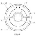
- Figure 2 shows an end elevation of the burner body having the distributor insert located therein,
- Figure 3 shows a sectional view through the burner body having the distributor insert located therein,
- Figure 4 shows a plan view of the burner body from above,
- Figure 5 shows a side elevation of the burner body with the distributor located therein shown in dotted lines,
- Figure 6 shows an end elevation of the burner having a closure cap fitted over the open end thereof, and
- Figure 7 shows a possible arrangement of the perforations in the upper surface of the burner body.
-
- Referring firstly to Figure 1, there is shown a
burner body 2 having a circular cross-section and being hollow over its entire length and further being provided with a plurality ofperforations 4 over a narrow sector of itsupper surface 6. The saidburner body 2 can be divided into saidupper regions 6 and alower region 10 by animaginary line 8 bisecting the cylindrical body, and this notion of upper and lower regions will be useful in explaining the invention below. - Also shown in Figure 1 is an
elongate distributor 12 having anend cap 14 to which is brazed a hemi-cylindricalelongate section 16 of substantively the same axial dimension as theburner body 10 having a pair offlanges tubular section 22 is ideally welded within the hemi-cylindrical section towards afree end 24 thereof so that a firstopen end 26 of the tubular section is substantially adjacent thefree end 24 of said hemi-cylindrical section. Saidtubular section 22 in use forms part of the mixing chamber of the burner and it is through this tubular section that a combustible fluid mixture flows before emerging into thelower region 10 of the burner body through thesecond opening 28 of said tubular section. - The
arrows distributor 12 is inserted into the burner body so that thezenith 34 of the hemi-cylindrical section 16 is immediately beneath an imaginary axial line bisecting the sector of perforations in theburner body 2. - It will also be seen from Figure 1 that the
flanges apertures 36, optionally of different diameters, spacings, and number to provide an effective means of distribution of combustible fluid mixture beneath theperforations 4 in the burner body. The sector ofperforations 4 in the burner body will be hereinafter referred to as the flame strip. - It can be seen from Figure 2 how the
burner body 2 is divided into two separate anddiscrete chambers flanges burner body 2, and the hemi-cylindrical section 16, together with thetubular section 22 effectively prevents any gas flow from thelower chamber 40 through to theupper chamber 38 except through theperforations 36. - In Figure 3, a sectional view is shown of the
burner body 2 having thedistributor 12 located therein so that only one end of theburner body 2 remains open. It will be seen from the figure that theend 26 of thetubular section 22 is substantially coplanar with the corresponding end of theburner body 2, and it is to this open end of the burner that a closure cap, optionally being provided with gas injector means, is fixed as shown at 42 in Figures 4, 5 and 6. Preferably, saidclosure cap 42 is welded to both the edges of the open end of theburner body 2, and the edges of the tubular section and hemi-cylindrical section so as to effectively seal onechamber 38 from theother chamber 40 and constrain any injected combustible fluid to flow firstly through thetubular section 22 as indicated in Figure 3 byarrows 44 and thence into thechamber 40 from where the gas can circumferentially flow around the inner walls of thebody 2 through theperforations 36 to be distributed thereby underneath the flame strip. - Finally, in Figure 7, the arrangement and shape of
perforations 4 provided in the upper surface of theburner body 2 is shown. It would be appreciated by the skilled person however that this arrangement is only one of a number of possible arrangements, and that these perforations and their shape may be chosen so as to satisfy particular burner application criteria. - In summary therefore, the invention describes a tubular burner consisting of a cylindrical tubular body initially open at either end into which a distributor component can be slidingly fitted. The tubular body is provided with rows of apertures over a narrow area of the uppermost surface thereof to give the burner a flame strip. The distributor is substantially the same axial length as the tubular burner body but of smaller cross-sectional dimension than said body allowing for sliding fitment of the distributor inside the burner body. In accordance with the invention, the distributor has a first tubular portion and a second extension portion which is effectively a continuation of the upper surface of said first tubular portion, and both the tubular portion and extension portion of the distributor are provided with axially aligned flanges on either side having a number of perforations. As the distributor is slid axially along the tubular burner body, the edges of the flanges engage with the inner walls of the tubular burner body and thus divide the burner body into an upper and lower chamber, the combustible air/gas mixture emerging from the tubular portion of the distributor into the lower chamber and subsequently being urged upwardly through the apertures in said flanges into the upper chamber before passing through the flame ports for combustion on the upper surface of said tubular body. The invention also relates to a distributor for use in such a burner.
Claims (9)
- A tubular burner comprising a tubular body being axially long in comparison to the dimensions of said cross-section, said body having an outer surface over an axially aligned portion of which is provided a plurality of perforations which portion constitutes the flame strip of said burner immediately beneath which an upper region of the burner is partially defined internally of said tubular body, said burner further comprising an elongate distributor of substantially the same axial length as the tubular burner body and being of smaller cross-sectional dimension than said body allowing for sliding fitment of said distributor therein, said distributor having a first tubular portion opening proximate one end of said burner body into which combustible fluid can be introduced, said first tubular portion having an upper surface which together with the flamestrip defines the upper region of said burner tubular body, and a second extension portion which is effectively a continuation of the upper surface of said first tubular portion and thus also defines the upper region of said body and constrains fluid emerging from the tubular portion to flow therebeneath, wherein both tubular portion and extension portion of the distributor are provided with axially aligned flanges having a number of perforations therein, said flanges contacting the inner walls of the burner body to effectively divide the inside of the burner body into said upper region immediately underneath the flamestrip and a lower region into which combustible fluid is urged from the tubular portion of said distributor, said fluid passing from the lower region into the upper region through said perforations.
- A burner according to claim 1 wherein the cross sections of the tubular body and distributor are predominantly arcuate.
- A burner according to claim 2 wherein the cross section of the tubular burner body and the tubular portion of the distributor are circular, the extension portion of said distributor being hemi-cylindrical.
- A burner according to claim 1 wherein the flanges of the distributor are provided on opposite sides of said distributor tubular portion and extension portion.
- A burner according to claim 4 wherein the flanges of the distributor are co-planar.
- A burner according to claim 1 wherein the tubular burner body is open at either end and the distributor is provided with a cap secured to the free end of said extension portion, said cap having dimensions corresponding to the dimensions of the tubular burner body to allow for both sliding fitment of said distributor within said body and sealing attachment of said cap to one of said open ends of said body.
- A burner according to claim 1 wherein the distributor consists of a cap portion to which is welded a hemi-cylindrical elongate section having a longitudinal axis substantially coincident with the longitudinal axis of the burner body, said section being orientated so that its zenith is directly beneath an axially parallel line bisecting the flamestrip, and a tubular portion secured within the hemi-cylindrical section having a first end coincident with a free end of the hemi-cylindrical section and a second end opening part way along said hemi-cylindrical section.
- A burner according to claim 7 wherein the hemi-cylindircal section is welded to the cap which is in turn sealingly secured to said burner body.
- A distributor for sliding insertion within a tubular burner body, said distributor being substantially the same axial length as the tubular burner body and being of smaller cross-sectional dimension than said body allowing for sliding fitment of said distributor therein, said distributor having a first tubular portion and a second extension portion which is effectively a continuation of the upper surface of said first tubular portion, wherein both tubular portion and extension portion of the distributor are provided with axially aligned flanges having a number of perforations therein.
Applications Claiming Priority (2)
| Application Number | Priority Date | Filing Date | Title |
|---|---|---|---|
| GBGB0027482.9A GB0027482D0 (en) | 2000-11-09 | 2000-11-09 | Tubular burner |
| GB0027482 | 2000-11-09 |
Publications (3)
| Publication Number | Publication Date |
|---|---|
| EP1209415A2 true EP1209415A2 (en) | 2002-05-29 |
| EP1209415A3 EP1209415A3 (en) | 2002-09-11 |
| EP1209415B1 EP1209415B1 (en) | 2006-03-08 |
Family
ID=9902933
Family Applications (1)
| Application Number | Title | Priority Date | Filing Date |
|---|---|---|---|
| EP01125601A Expired - Lifetime EP1209415B1 (en) | 2000-11-09 | 2001-10-26 | Tubular burner |
Country Status (5)
| Country | Link |
|---|---|
| US (1) | US6461152B2 (en) |
| EP (1) | EP1209415B1 (en) |
| AT (1) | ATE319965T1 (en) |
| DE (1) | DE60117659D1 (en) |
| GB (1) | GB0027482D0 (en) |
Cited By (2)
| Publication number | Priority date | Publication date | Assignee | Title |
|---|---|---|---|---|
| EP1985921A3 (en) * | 2007-04-27 | 2008-11-12 | Paloma Industries, Ltd. | Burner |
| WO2009112909A2 (en) * | 2008-03-10 | 2009-09-17 | Worgas-Bruciatori - S.R.L. | Burner provided with noise reducing means |
Families Citing this family (12)
| Publication number | Priority date | Publication date | Assignee | Title |
|---|---|---|---|---|
| IT1292721B1 (en) * | 1997-04-28 | 1999-02-11 | Worgas Bruciatori Srl | BURNER FOR GASEOUS FUELS |
| IT1315671B1 (en) * | 2000-09-26 | 2003-03-14 | Worgas Bruciatori Srl | LOW NOISE RAMPET BURNER |
| US7052273B2 (en) | 2003-01-27 | 2006-05-30 | Millomat Stampings Inc. | Premixed fuel burner assembly |
| US6945774B2 (en) * | 2003-03-07 | 2005-09-20 | Weber-Stephen Products Co. | Gas burner with flame stabilization structure |
| ITMO20030154A1 (en) * | 2003-05-23 | 2004-11-24 | Worgas Bruciatori Srl | MODULABLE BURNER |
| GB2410789B (en) * | 2004-02-06 | 2009-06-10 | Sit Bray Ltd | Air/gas burner system |
| ITPN20060065A1 (en) * | 2006-09-04 | 2008-03-05 | Timoteo Pezzutti | ATMOSPHERIC GAS BURNER WITH SEQUENTIAL SYSTEM WITH SUPERMINIMUM DEVICE |
| KR101215091B1 (en) * | 2008-02-01 | 2012-12-24 | 가부시키가이샤 아이에이치아이 | combustion heater |
| US20090311641A1 (en) * | 2008-06-13 | 2009-12-17 | Gunther Berthold | Gas flame stabilization method and apparatus |
| ITMI20110390A1 (en) * | 2011-03-11 | 2012-09-12 | Bertelli & Partners Srl | GAS BURNER PERFECTED FOR PREMIXED COMBUSTION |
| EP3191766A4 (en) * | 2014-09-08 | 2018-08-08 | W.C. Bradley Co. | Top ported burner |
| WO2023235183A1 (en) * | 2022-05-29 | 2023-12-07 | Lantec Products, Inc. | Heating apparatus with aphlogistic burner |
Citations (1)
| Publication number | Priority date | Publication date | Assignee | Title |
|---|---|---|---|---|
| US5743727A (en) | 1997-01-21 | 1998-04-28 | Burner Systems International, Inc. | Premixed gas burner |
Family Cites Families (8)
| Publication number | Priority date | Publication date | Assignee | Title |
|---|---|---|---|---|
| US1507791A (en) * | 1924-02-09 | 1924-09-09 | Mortimer L Packer | Gas burner |
| US3156292A (en) * | 1961-04-24 | 1964-11-10 | Richard W Ross | Gas burner with secondary air supply |
| JPS5343025U (en) * | 1976-09-18 | 1978-04-13 | ||
| JPS5653308A (en) * | 1979-10-03 | 1981-05-12 | Hitachi Ltd | Liquid fuel evaporation type combustor |
| US4976609A (en) * | 1988-12-08 | 1990-12-11 | The Frymaster Corporation | Flashback resistant infrared gas burner apparatus |
| GB2237104B (en) * | 1989-10-20 | 1993-07-21 | Bowin Designs Pty Ltd | Gas burner |
| DE9409247U1 (en) * | 1994-06-08 | 1994-09-01 | Buderus Heiztechnik Gmbh | Atmospheric gas burner |
| DE19602506C1 (en) * | 1996-01-25 | 1997-05-15 | Buderus Heiztechnik Gmbh | Mixing chamber for pre-mixing gas burner |
-
2000
- 2000-11-09 GB GBGB0027482.9A patent/GB0027482D0/en not_active Ceased
-
2001
- 2001-10-22 US US09/682,818 patent/US6461152B2/en not_active Expired - Fee Related
- 2001-10-26 AT AT01125601T patent/ATE319965T1/en not_active IP Right Cessation
- 2001-10-26 DE DE60117659T patent/DE60117659D1/en not_active Expired - Lifetime
- 2001-10-26 EP EP01125601A patent/EP1209415B1/en not_active Expired - Lifetime
Patent Citations (1)
| Publication number | Priority date | Publication date | Assignee | Title |
|---|---|---|---|---|
| US5743727A (en) | 1997-01-21 | 1998-04-28 | Burner Systems International, Inc. | Premixed gas burner |
Cited By (4)
| Publication number | Priority date | Publication date | Assignee | Title |
|---|---|---|---|---|
| EP1985921A3 (en) * | 2007-04-27 | 2008-11-12 | Paloma Industries, Ltd. | Burner |
| US8282391B2 (en) | 2007-04-27 | 2012-10-09 | Paloma Industries, Limited | Burner |
| WO2009112909A2 (en) * | 2008-03-10 | 2009-09-17 | Worgas-Bruciatori - S.R.L. | Burner provided with noise reducing means |
| WO2009112909A3 (en) * | 2008-03-10 | 2010-06-10 | Worgas-Bruciatori - S.R.L. | Burner provided with noise reducing means |
Also Published As
| Publication number | Publication date |
|---|---|
| EP1209415A3 (en) | 2002-09-11 |
| US20020055079A1 (en) | 2002-05-09 |
| US6461152B2 (en) | 2002-10-08 |
| EP1209415B1 (en) | 2006-03-08 |
| DE60117659D1 (en) | 2006-05-04 |
| ATE319965T1 (en) | 2006-03-15 |
| GB0027482D0 (en) | 2000-12-27 |
Similar Documents
| Publication | Publication Date | Title |
|---|---|---|
| EP1209415B1 (en) | Tubular burner | |
| JP4743548B2 (en) | Combustion device | |
| US6036481A (en) | Burner with flame retainer insert | |
| US5402567A (en) | Method of making a jet burner construction | |
| JP2007225267A (en) | Combustor | |
| US7052273B2 (en) | Premixed fuel burner assembly | |
| KR100495505B1 (en) | Multi-Control Possible The Gas Burner | |
| JP2004144467A (en) | Premixed gas combustion burner having separable flame hole part | |
| US20050026100A1 (en) | Inshot burner | |
| KR100864846B1 (en) | Premixed combustion burner | |
| KR100420002B1 (en) | premixed metal fiber burner | |
| JPH0152644B2 (en) | ||
| US5324195A (en) | Jet burner construction, heating apparatus utilizing the jet burner construction and methods of making the same | |
| KR0126902B1 (en) | Low nitrogen oxide rurner | |
| KR20030021915A (en) | Bunsen gas burner of gas heater | |
| EP0661496B1 (en) | Improvements relating to gas burners and flamestrips therefor | |
| JP3426816B2 (en) | Low NOx gas combustion device | |
| JP2001056107A (en) | Gas burner | |
| JP4803430B2 (en) | Combustion device and combustion unit | |
| JP4622100B2 (en) | Low NOx combustor for gas turbine | |
| KR0126904B1 (en) | LOW NOx BURNER | |
| JP2548398B2 (en) | Burner | |
| JPS5818009Y2 (en) | staged combustor | |
| JP4947340B2 (en) | Two-stage combustion device | |
| JP3101246B2 (en) | Combustion equipment |
Legal Events
| Date | Code | Title | Description |
|---|---|---|---|
| PUAI | Public reference made under article 153(3) epc to a published international application that has entered the european phase |
Free format text: ORIGINAL CODE: 0009012 |
|
| AK | Designated contracting states |
Kind code of ref document: A2 Designated state(s): AT BE CH CY DE DK ES FI FR GB GR IE IT LI LU MC NL PT SE TR |
|
| AX | Request for extension of the european patent |
Free format text: AL;LT;LV;MK;RO;SI |
|
| PUAL | Search report despatched |
Free format text: ORIGINAL CODE: 0009013 |
|
| AK | Designated contracting states |
Kind code of ref document: A3 Designated state(s): AT BE CH CY DE DK ES FI FR GB GR IE IT LI LU MC NL PT SE TR |
|
| AX | Request for extension of the european patent |
Free format text: AL;LT;LV;MK;RO;SI |
|
| 17P | Request for examination filed |
Effective date: 20030121 |
|
| AKX | Designation fees paid |
Designated state(s): AT BE CH CY DE DK ES FI FR GB GR IE IT LI LU MC NL PT SE TR |
|
| RIN1 | Information on inventor provided before grant (corrected) |
Inventor name: WOOD, GRAHAM,C/O BRAY BURNERS LTD. Inventor name: DENNIS LEWISC/O BRAY BURNERS LTD Inventor name: HART, EDWARD,C/O BRAY BURNERS LTD. |
|
| 17Q | First examination report despatched |
Effective date: 20050323 |
|
| GRAP | Despatch of communication of intention to grant a patent |
Free format text: ORIGINAL CODE: EPIDOSNIGR1 |
|
| GRAS | Grant fee paid |
Free format text: ORIGINAL CODE: EPIDOSNIGR3 |
|
| GRAA | (expected) grant |
Free format text: ORIGINAL CODE: 0009210 |
|
| RAP1 | Party data changed (applicant data changed or rights of an application transferred) |
Owner name: SIT-BRAY LIMITED |
|
| AK | Designated contracting states |
Kind code of ref document: B1 Designated state(s): AT BE CH CY DE DK ES FI FR GB GR IE IT LI LU MC NL PT SE TR |
|
| PG25 | Lapsed in a contracting state [announced via postgrant information from national office to epo] |
Ref country code: IT Free format text: LAPSE BECAUSE OF FAILURE TO SUBMIT A TRANSLATION OF THE DESCRIPTION OR TO PAY THE FEE WITHIN THE PRESCRIBED TIME-LIMIT;WARNING: LAPSES OF ITALIAN PATENTS WITH EFFECTIVE DATE BEFORE 2007 MAY HAVE OCCURRED AT ANY TIME BEFORE 2007. THE CORRECT EFFECTIVE DATE MAY BE DIFFERENT FROM THE ONE RECORDED. Effective date: 20060308 Ref country code: LI Free format text: LAPSE BECAUSE OF FAILURE TO SUBMIT A TRANSLATION OF THE DESCRIPTION OR TO PAY THE FEE WITHIN THE PRESCRIBED TIME-LIMIT Effective date: 20060308 Ref country code: AT Free format text: LAPSE BECAUSE OF FAILURE TO SUBMIT A TRANSLATION OF THE DESCRIPTION OR TO PAY THE FEE WITHIN THE PRESCRIBED TIME-LIMIT Effective date: 20060308 Ref country code: CH Free format text: LAPSE BECAUSE OF FAILURE TO SUBMIT A TRANSLATION OF THE DESCRIPTION OR TO PAY THE FEE WITHIN THE PRESCRIBED TIME-LIMIT Effective date: 20060308 Ref country code: FI Free format text: LAPSE BECAUSE OF FAILURE TO SUBMIT A TRANSLATION OF THE DESCRIPTION OR TO PAY THE FEE WITHIN THE PRESCRIBED TIME-LIMIT Effective date: 20060308 Ref country code: NL Free format text: LAPSE BECAUSE OF FAILURE TO SUBMIT A TRANSLATION OF THE DESCRIPTION OR TO PAY THE FEE WITHIN THE PRESCRIBED TIME-LIMIT Effective date: 20060308 Ref country code: BE Free format text: LAPSE BECAUSE OF FAILURE TO SUBMIT A TRANSLATION OF THE DESCRIPTION OR TO PAY THE FEE WITHIN THE PRESCRIBED TIME-LIMIT Effective date: 20060308 |
|
| REG | Reference to a national code |
Ref country code: GB Ref legal event code: FG4D |
|
| RIN1 | Information on inventor provided before grant (corrected) |
Inventor name: WOOD, GRAHAM,C/O BRAY BURNERS LTD. Inventor name: HART, EDWARD,C/O BRAY BURNERS LTD. Inventor name: LEWIS, DENNISC/O BRAY BURNERS LTD |
|
| REG | Reference to a national code |
Ref country code: CH Ref legal event code: EP |
|
| REG | Reference to a national code |
Ref country code: IE Ref legal event code: FG4D |
|
| REF | Corresponds to: |
Ref document number: 60117659 Country of ref document: DE Date of ref document: 20060504 Kind code of ref document: P |
|
| PG25 | Lapsed in a contracting state [announced via postgrant information from national office to epo] |
Ref country code: SE Free format text: LAPSE BECAUSE OF FAILURE TO SUBMIT A TRANSLATION OF THE DESCRIPTION OR TO PAY THE FEE WITHIN THE PRESCRIBED TIME-LIMIT Effective date: 20060608 Ref country code: DK Free format text: LAPSE BECAUSE OF FAILURE TO SUBMIT A TRANSLATION OF THE DESCRIPTION OR TO PAY THE FEE WITHIN THE PRESCRIBED TIME-LIMIT Effective date: 20060608 |
|
| PG25 | Lapsed in a contracting state [announced via postgrant information from national office to epo] |
Ref country code: DE Free format text: LAPSE BECAUSE OF FAILURE TO SUBMIT A TRANSLATION OF THE DESCRIPTION OR TO PAY THE FEE WITHIN THE PRESCRIBED TIME-LIMIT Effective date: 20060609 |
|
| PG25 | Lapsed in a contracting state [announced via postgrant information from national office to epo] |
Ref country code: ES Free format text: LAPSE BECAUSE OF FAILURE TO SUBMIT A TRANSLATION OF THE DESCRIPTION OR TO PAY THE FEE WITHIN THE PRESCRIBED TIME-LIMIT Effective date: 20060619 |
|
| PG25 | Lapsed in a contracting state [announced via postgrant information from national office to epo] |
Ref country code: PT Free format text: LAPSE BECAUSE OF FAILURE TO SUBMIT A TRANSLATION OF THE DESCRIPTION OR TO PAY THE FEE WITHIN THE PRESCRIBED TIME-LIMIT Effective date: 20060808 |
|
| NLV1 | Nl: lapsed or annulled due to failure to fulfill the requirements of art. 29p and 29m of the patents act | ||
| REG | Reference to a national code |
Ref country code: CH Ref legal event code: PL |
|
| PG25 | Lapsed in a contracting state [announced via postgrant information from national office to epo] |
Ref country code: IE Free format text: LAPSE BECAUSE OF NON-PAYMENT OF DUE FEES Effective date: 20061026 |
|
| PG25 | Lapsed in a contracting state [announced via postgrant information from national office to epo] |
Ref country code: MC Free format text: LAPSE BECAUSE OF NON-PAYMENT OF DUE FEES Effective date: 20061031 |
|
| PLBE | No opposition filed within time limit |
Free format text: ORIGINAL CODE: 0009261 |
|
| STAA | Information on the status of an ep patent application or granted ep patent |
Free format text: STATUS: NO OPPOSITION FILED WITHIN TIME LIMIT |
|
| 26N | No opposition filed |
Effective date: 20061211 |
|
| EN | Fr: translation not filed | ||
| PG25 | Lapsed in a contracting state [announced via postgrant information from national office to epo] |
Ref country code: GR Free format text: LAPSE BECAUSE OF FAILURE TO SUBMIT A TRANSLATION OF THE DESCRIPTION OR TO PAY THE FEE WITHIN THE PRESCRIBED TIME-LIMIT Effective date: 20060609 Ref country code: FR Free format text: LAPSE BECAUSE OF FAILURE TO SUBMIT A TRANSLATION OF THE DESCRIPTION OR TO PAY THE FEE WITHIN THE PRESCRIBED TIME-LIMIT Effective date: 20070309 |
|
| PG25 | Lapsed in a contracting state [announced via postgrant information from national office to epo] |
Ref country code: LU Free format text: LAPSE BECAUSE OF NON-PAYMENT OF DUE FEES Effective date: 20061026 Ref country code: TR Free format text: LAPSE BECAUSE OF FAILURE TO SUBMIT A TRANSLATION OF THE DESCRIPTION OR TO PAY THE FEE WITHIN THE PRESCRIBED TIME-LIMIT Effective date: 20060308 |
|
| PG25 | Lapsed in a contracting state [announced via postgrant information from national office to epo] |
Ref country code: FR Free format text: LAPSE BECAUSE OF FAILURE TO SUBMIT A TRANSLATION OF THE DESCRIPTION OR TO PAY THE FEE WITHIN THE PRESCRIBED TIME-LIMIT Effective date: 20060308 Ref country code: CY Free format text: LAPSE BECAUSE OF FAILURE TO SUBMIT A TRANSLATION OF THE DESCRIPTION OR TO PAY THE FEE WITHIN THE PRESCRIBED TIME-LIMIT Effective date: 20060308 |
|
| PGFP | Annual fee paid to national office [announced via postgrant information from national office to epo] |
Ref country code: GB Payment date: 20130912 Year of fee payment: 13 |
|
| GBPC | Gb: european patent ceased through non-payment of renewal fee |
Effective date: 20141026 |
|
| PG25 | Lapsed in a contracting state [announced via postgrant information from national office to epo] |
Ref country code: GB Free format text: LAPSE BECAUSE OF NON-PAYMENT OF DUE FEES Effective date: 20141026 |