EP1209036A2 - Electrical junction box for a vehicle - Google Patents
Electrical junction box for a vehicle Download PDFInfo
- Publication number
- EP1209036A2 EP1209036A2 EP01309933A EP01309933A EP1209036A2 EP 1209036 A2 EP1209036 A2 EP 1209036A2 EP 01309933 A EP01309933 A EP 01309933A EP 01309933 A EP01309933 A EP 01309933A EP 1209036 A2 EP1209036 A2 EP 1209036A2
- Authority
- EP
- European Patent Office
- Prior art keywords
- bus bars
- module
- fuse
- welding tabs
- rows
- Prior art date
- Legal status (The legal status is an assumption and is not a legal conclusion. Google has not performed a legal analysis and makes no representation as to the accuracy of the status listed.)
- Withdrawn
Links
Images


Classifications
-
- B—PERFORMING OPERATIONS; TRANSPORTING
- B60—VEHICLES IN GENERAL
- B60R—VEHICLES, VEHICLE FITTINGS, OR VEHICLE PARTS, NOT OTHERWISE PROVIDED FOR
- B60R16/00—Electric or fluid circuits specially adapted for vehicles and not otherwise provided for; Arrangement of elements of electric or fluid circuits specially adapted for vehicles and not otherwise provided for
- B60R16/02—Electric or fluid circuits specially adapted for vehicles and not otherwise provided for; Arrangement of elements of electric or fluid circuits specially adapted for vehicles and not otherwise provided for electric constitutive elements
- B60R16/023—Electric or fluid circuits specially adapted for vehicles and not otherwise provided for; Arrangement of elements of electric or fluid circuits specially adapted for vehicles and not otherwise provided for electric constitutive elements for transmission of signals between vehicle parts or subsystems
- B60R16/0238—Electrical distribution centers
-
- H—ELECTRICITY
- H01—ELECTRIC ELEMENTS
- H01H—ELECTRIC SWITCHES; RELAYS; SELECTORS; EMERGENCY PROTECTIVE DEVICES
- H01H85/00—Protective devices in which the current flows through a part of fusible material and this current is interrupted by displacement of the fusible material when this current becomes excessive
- H01H85/02—Details
- H01H85/20—Bases for supporting the fuse; Separate parts thereof
- H01H2085/2075—Junction box, having holders integrated with several other holders in a particular wiring layout
- H01H2085/208—Junction box, having holders integrated with several other holders in a particular wiring layout specially adapted for vehicles
-
- Y—GENERAL TAGGING OF NEW TECHNOLOGICAL DEVELOPMENTS; GENERAL TAGGING OF CROSS-SECTIONAL TECHNOLOGIES SPANNING OVER SEVERAL SECTIONS OF THE IPC; TECHNICAL SUBJECTS COVERED BY FORMER USPC CROSS-REFERENCE ART COLLECTIONS [XRACs] AND DIGESTS
- Y10—TECHNICAL SUBJECTS COVERED BY FORMER USPC
- Y10S—TECHNICAL SUBJECTS COVERED BY FORMER USPC CROSS-REFERENCE ART COLLECTIONS [XRACs] AND DIGESTS
- Y10S439/00—Electrical connectors
- Y10S439/949—Junction box with busbar for plug-socket type interconnection with receptacle
Definitions
- the present invention relates to an electrical junction box for a vehicle, in particular a box to be connected to a wire harness for a vehicle.
- the invention also provides a vehicle such as an automobile having the electrical junction box mounted on it.
- junction box 1 shown in present Fig. 14 in JP-A-2000-112691 (corresponding to EP-A-1145914 and USSN 09/833595).
- the junction box of Fig. 14 is intended to be thin, capable of permitting circuit alteration and reducing time and labour when it is assembled from component parts.
- a connector connection circuit (base circuit), a fuse connection circuit, and a relay connection circuit provided in the junction box are formed separately as a connector module 2, a fuse module 3 and a relay module 4.
- the connector module 2, the fuse module 3 and the relay module 4 are incorporated in the casing composed of the lower case part 5 and the upper case part 6.
- bus bars 2a, 3a and 4a are fixed to insulation substrates 2b, 3b and 4b respectively, and project from the periphery of the insulation substrates where they are welded to each other.
- the whole circuit of the junction box is divided into the connector module 2, the fuse module 3 and the relay module, it can be avoided that tabs of the bus bars overlap on each other. Thus excessive layering of the bus bars can be prevented, and the junction box can be thin. Further the circuits of the bus bars can be wired easily. Thus it is possible to reduce the area of the bus bars of each module. Consequently, even though the connector connection bus bars, the fuse connection bus bars and the relay connection bus bars are separately formed, it is possible to reduce the total area of the bus bars and avoid increase of the area of the junction box.
- the junction box permits alteration of the specification easily.
- the welding portions for connecting the modules to each other are disposed on the three sides of the connector module. Thus it is necessary to move a welding machine or the junction box in correspondence to each welding position when carrying out welding. Therefore much time and labour are required in the welding.
- an electrical junction box having a connector module providing a connector connection circuit which in use makes electrical connection to at least one electrical connector, a fuse module providing a fuse connection circuit which in use makes electrical connection to a plurality of fuses, and a relay module providing a relay connection circuit which in use makes electrical connection to a plurality of relays
- the connector module comprising a plurality of insulation substrates stacked one on another to form a layered assembly having a pair of main faces and a plurality of sides, and bus bars fixed on the insulation substrates, the bus bars providing a plurality of projecting first welding tabs which are aligned with one another in at least one linear row adjacent one of the sides of the layered assembly
- the fuse module comprising one or more insulation substrates and bus bars fixed thereon and arranged to be connected in use to the fuses and providing a plurality of projecting second welding tabs confronting the first welding tabs of the connector module
- the relay module comprising one or more insulation substrates and bus bars fixed thereon and arranged
- the welding tabs of the connector module, the welding tabs of the fuse module and the welding tabs of the relay module may be arranged linearly in one or more rows at a single side of the connector module.
- the tabs of the connector module, the fuse module and the relay module can be welded easily by moving a welding machine relative to the components linearly and sequentially.
- the welding tabs can be welded to each other with a small number of operations and thus the welding efficiency can be improved greatly.
- the electrical junction box has a casing having upper and lower casing parts, and the connector module, fuse module and relay module are mounted in the casing with the layered assembly of the connector module lying horizontally and the insulation substrate or substrates of the fuse module extending vertically, the fuse module being adapted to receive the fuses in use in an upper row and a lower row, and wherein the casing has a lateral opening for insertion and removal of the fuses, the first welding tabs of the connector module are aligned in a vertically spaced pair of said linear rows, the second welding tabs of the fuse module project in a pair of aligned rows at an upper side and a lower side respectively of the insulation substrate or substrates of the fuse module and confront the first welding tabs of the pair of linear rows thereof, and the confronting first welding tabs and second welding tabs are welded to each other at the upper and lower sides of the insulation substrate or substrates of the fuse module.
- This construction allows the connector module and the fuse module to be disposed in a direction in which the connector module and the fuse module intersect with each other.
- the welding tabs of the two modules project at upper and lower sides of the intersection region and are arranged linearly in rows. Therefore the welding tabs can be welded to each other successively along the same lines, with the confronting welding tabs layered on each other.
- the relay module may be disposed above or below the connector module in such a way that the relay module is proximate to the side where the fuse module is disposed.
- the welding tabs of the relay module may project at positions where they confront the welding tabs of the connector module and the welding tabs of the fuse module, the welding tabs of the relay module being welded to the welding tabs of the connector module and/or the welding tabs of the fuse module.
- the welding tabs of the relay module and those of the fuse module can be reduced in number and further the welding tabs can be connected to each other by layering them triply.
- An electronic control unit may be disposed so that the connector module is between it and the relay module, or so that it is between the connector module and the relay module.
- Welding tabs of the connector module projecting from different insulation substrates thereof layered on each other may be welded to each other to connect the different layers to each other.
- a terminal of a bus bar may be connected to the connector module, the fuse module and the relay module directly or through a relay terminal. Further a fuse-mounting portion and a relay-mounting portion formed on a substrate of the fuse module and/or a substrate of the relay module may be exposed at the outer surface of the upper case, the lower case and/or the side of the casing.
- the welding tabs of the connector module, the fuse module and the relay module may be welded to each other for example by resistance welding, ultrasonic welding or laser welding. Of these welding methods, resistance welding is most preferred.
- an electrical junction box having a connector module providing a connector connection circuit which in use makes electrical connection to at least one electrical connector, and a fuse module providing a fuse connection circuit which in use makes electrical connection to a plurality of fuses
- the connector module comprising a plurality of insulation substrates stacked one on another to form a layered assembly having a pair of main faces and a plurality of sides, and bus bars fixed on the insulation substrates, the bus bars providing a plurality of projecting first welding tabs adjacent one of the sides of the layered assembly
- the fuse module comprising one or more insulation substrates and bus bars fixed thereon and arranged to be connected in use to the fuses and providing a plurality of projecting second welding tabs
- the connector module and the fuse module being mutually disposed so that the insulation substrate or substrates of the fuse module are perpendicular to the main faces of the layered assembly of the connector module, the fuse module having a housing having a plurality of fuse receiving locations arranged in two parallel rows extending in a
- bus bars of the fuse module can be arranged regularly, it is possible to make the fuse module compact.
- one bus bar is connected to the load application side output terminal of the fuse, it is possible to allow all the bus bars to have the same configuration. Thus it is possible to enhance the yield of the material for the bus bars.
- the first welding tabs of the connector module are formed of projecting portions of the bus bars thereof which are bent so that the first welding tabs are arranged in two linear rows projecting in two opposite directions respectively, which two linear rows extend parallel to the longitudinal direction of the fuse module and constitute respectively the first and second arrays of the first welding tabs confronting, and welded to, the linear rows of the welding tabs of the fuse module.
- the welding tabs of the bus bars of the fuse module are arranged at a position where they confront the welding tabs of the connector module which project in two different directions. By disposing the welding tabs of the connector module in this manner, they can be overlaid on the welding tabs of the fuse module. Further because the bus bars of the connection module may be arranged regularly, it is possible to make the connector module compact.
- a plurality of the pressure connecting terminals which constitute power supply side input terminals for the fuses are disposed in a row at a first side of the respective row of fuse receiving locations adjacent the other of the rows of fuse receiving locations, and a plurality of the pressure connecting terminals which constitute load application side output terminals for the fuses are disposed in a row at a second side of the respective row of fuse receiving locations distal from the other of the rows of fuse receiving locations.
- the bus bars to be respectively connected to the load application side output terminals of the fuses can be formed in the same shape and configuration, as described above.
- the pressure connection terminals may be branched from one end of the bus bar to be connected to the power-supply side input terminal, whereas one welding tab is formed at the other end thereof. Therefore, the bus bars to be connected to the power-supply side input terminals may have respective different configurations.
- the welding tabs of the bus bars to be connected to the output terminals respectively and the welding tabs of the bus bars to be connected to the input terminals respectively in a row, it is necessary to make the former welding tab longer than the latter tab or vice versa.
- the bus bars to be connected to the input terminals having a smaller number of welding tabs, are positioned at the side where the two rows of the fuse module are proximate to each other, and the length of each welding tab is increased to reduce the cost of material.
- the invention further provides a method of making the fuse module, by forming bus bars as described above, and mounting them on one or more insulation substrates.
- the method allows the entire width of the conductive metal plate for the bus bars to be connected to the power supply side input terminals to be small. Consequently it is possible to use a metal plate for the bus bars to be connected to the power supply side input terminal, which has the same width as the conductive metal plate for the bus bars to be connected to the load application side output terminals. Thus it is possible to punch the bus bars of the first and second rows with the same compact press.
- Fig. 1 shows a junction box 10 adapted to be connected to at least one wire harness for a vehicle and comprising a connector module 11, a fuse module 12, a relay module 13, a lower case 14, an upper case 15 and an electronic control unit 16.
- the upper and lower cases 14, 15 and the fuse module housing 32 are of moulded plastics material.
- the relay module 13, the connector module 11 and the electronic control unit 16 are sequentially stacked on the lower case 14 and shown horizontal in the drawings, though the orientation of the box in use may be different.
- the upper case 15 is mounted on them.
- a fuse module accommodation region 15a is formed at one side as an opening of the peripheral walls between the lower case 14 and the upper case 15. Fuses 30 (see Figs. 4 and 5) are in use mounted on the fuse module 12 from one side thereof.
- the fuse module 12 is disposed upright in the fuse module accommodation region 15a.
- Relays 40 mounted in use on the lower surface of the relay module 13 are exposed to the outside through openings formed in the lower case 14.
- a plurality of connector accommodation portions in the form of sockets 14a which in use receive connectors (not shown) to be connected to the connector module 11 are formed on the lower surface of the lower case 14.
- the connector module 11 is constructed of a plurality of circuit structures 23, layered one upon another, each having an insulation plate 22 and bus bars 21 forming a circuit having a required configuration fixed to the insulation plate 22.
- the bus bars 21 are formed from conductive metal sheet. Tabs 21a projecting at ends of the bus bars 21 of each of the circuit structures 23 project into the connector sockets 14a of the lower case 14.
- the connectors (not shown) mounted on an end of a wire harness are fitted in the connector sockets 14a to connect their terminals to the tabs 21c of the connector module 11.
- a plurality of welding tabs 21b, 21c formed by bending ends of selected bus bars 21 upward and downward in an L-shape are arranged collectively in respective linear rows.
- a long and narrow opening 11a for receiving intermediate tabs 13a (described later) projecting from the relay module 13 is formed at a position near the centre of the connector module 11 parallel to the rows of tabs 21b, 21c.
- Tabs 21d to be connected to the intermediate tabs 13a of the relay module 13 are formed in a row on the connector module 11 along an edge of the opening 11a by bending up ends of selected bus bars 21.
- the fuse module 12 which is disposed upright and adjacent one side edge of the connector module 11 has a housing 32 within the cases 14, 15 defining a plurality of fuse receiving sockets 33, 34 arranged in two rows in the longitudinal (horizontal) direction thereof.
- the fuse module 12 of Fig. 7A there is a single vertical insulation substrate 31.
- bus bars 35, 36, 37 and 38 which are bent to provide pairs of slotted pressure connection terminals 35a, 36a, 37a, 38a projecting horizontally into the fuse receiving sockets 33, 34 are fixed on the insulation substrate 31 in two rows.
- the pressure connection terminals 35a, 36a, 37a, 38a make detachable pressure gripping connection to the power supply side input terminal 30a and a load application side output terminal 30b of each of the fuses 30 which project into the sockets 33 of the upper row (first row) and the sockets 34 of the lower row (second row).
- the fuses 30 are arranged vertically.
- the upper row has the bus bars 35, 36 and the lower row has the bus bars 37, 38.
- the bus bars 35, 36 of the first (upper) row are bent upward so that welding tabs 35b, 36b of the fuse module 12 are formed on the upper ends of the bus bars 35, 36 respectively and lie in a linear row projecting from the upper side of the housing 32 and extending in the longitudinal direction thereof.
- the bus bars 37, 38 of the second (lower) row are bent downward so that welding tabs 37a, 37b of the fuse module 12 are formed on the lower ends of the bus bars 37, 38 respectively and are arranged in a linear row projecting from the lower side of the housing 32 and extending in the longitudinal direction thereof.
- the bus bars 35 - 38 are on a single insulation substrate 31, so that it is necessary to shape and bend bus bars as shown for bus bar 38 in Fig. 7B, in order that the two pressure connection terminals 37A, 37B are vertically aligned.
- the insulation substrate 31 may be made by moulding, with the bus bars incorporated by in situ moulding. Alternatively the bus bars may be fixed on one or both surfaces of a pre-formed substrate.
- the bus bars 35, 37 are on one substrate and the bus bars 36, 38 on the other substrate.
- the front substrate (with respect to the fuses 30) has apertures through which the pressure connection terminals project from the rear substrate.
- the bus bars 35 - 38 of the fuse module 12 are formed by punching conductive metal sheets 100 and 101.
- Fig. 9A shows how the bus bars 35 of the first row to be connected to the load application side output terminals of the fuses and the bus bars 37 of the second row to be connected also to the load application side output terminals of the fuses are punched from the first conductive metal sheet 100.
- the bus bars 35, 37 as punched from the sheet 100 are arranged such that the terminals 35a, 37a confront each other and the welding tabs 35b, 37b of the fuse module 12 face outwardly in opposite directions.
- the bus bars 35, 37 are spaced in the sheet 100 at regular intervals. After being punched, each of the bus bars 35, 37 is bent at the position shown with bold full lines.
- Fig. 9B shows how the load application side output terminals 30b of the fuses 30 and the bus bars 35, 37 are connected to each other by pressure connection when the bus bars 35, 37 are mounted in the fuse module 12 and also shows the positions where the tabs 37a, 37b of the bus bars 35, 37 are welded to the welding tabs 21b, 21c of the connector module 11 respectively.
- Fig. 10A shows how the bus bars 36 of the first row to be connected to the power source side input terminals of the fuses and the bus bars 38 of the second row also to be connected to the power source side input terminals of the fuses are punched from the conductive metal sheet 100.
- the pressure connection terminals 36a, 38a are in respective rows having the same configuration.
- the terminals 36a, 38a are branched in groups from the welding tabs 36b, 38b, the configuration of the welding tabs 36b and that of the welding tabs 38b are different, and the welding tabs 36b, 38b are staggered from each other in the longitudinal direction of the rows.
- the terminals 36a, 38a are disposed in reverse directions, extending outwardly.
- the welding tabs 36b, 38b are disposed alongside each other interdigitally in the same region of the sheet 101.
- bus bars 36, 38 are bent at the positions shown with bold full lines in Fig. 10A, and then the positions of the bus bars 36, 38 are changed as shown in Fig. 8B (as if the bus bars 36, 38 were flat) so that the pressure welding terminals 36a, 38aa are disposed face to face.
- Figs. 7A and 7B show an alternative method of bending the bus bars 37, 38.
- Fig. 10C shows how the power supply side input terminals 30a of the fuses 30 and the bus bars 36, 38 are connected to each other by pressure connection after the bus bars 36, 38 are mounted in the fuse module 12 and also shows the positions where tabs 36b, 38b of the bus bars 36, 38 are welded to the welding tabs 21b, 21c of the connector module 11 respectively.
- the positions of the welding tabs 36b of the bus bars 36 and those of the welding tabs 38b of the bus bars 38 are respectively such that the welding tabs 36b are interposed among the welding tabs 35b in their linear row and likewise the welding tabs 38b are interposed among the welding tabs 37b in their linear row, as shown in Fig. 5.
- the length of bent portions 36c of the bus bars 36 and of bent portions 38c of the bus bars 38 are greater than the length of bent portions 35c of the bus bars 35 and bent portions 37c of the bus bars 37 respectively.
- bus bars 36, 38 are formed from the conductive metal sheet, the material of the sheet can be used with minimal waste.
- Fig. 11 Let it be supposed that as shown in Fig. 11, bus bars 36' arranged in a row and bus bars 38' arranged in another row are taken from a conductive metal sheet 101', with the pressure welding terminals 36a' of the bus bars 36' and pressure welding terminals 38a' of the bus bars 38' confronting each other and with welding tabs 36b' and 38b' facing outwardly in opposite directions in a developed configuration. In this case, portions of large area of the conductive metal sheet 101' covered with oblique lines in Fig. 11 are wasted.
- the welding tabs 36b, 38b are taken from the same region of the conductive metal sheet 101, as shown in Fig. 10, a small portion thereof is wasted. More specifically, it is possible to make the width W1 of the conductive metal plate 101 less than the width W3 of the conductive metal plate 101' by the length of the welding tab 36b' (38b'). Thus it is possible to make the width W1 of the conductive metal sheet 101 for the bus bars to be connected to the power supply side input terminals almost equal to the width W2 of the conductive metal sheet 100 for the bus bars to be connected to the load application side output terminals. The bus bars can be easily produced at low cost.
- Fig. 4 shows a cover 39 for the fuses 30, fitting on the cases 14, 15.
- the relay module 13 is disposed below the connector module 11 and at a position proximate to the side where the fuse module 12 is arranged.
- Bus bars 41 are mounted on a substrate 42 of the relay module 13.
- the body of the relay 40 engages the lower surface of the substrate 42.
- a terminal 40a of the relay 40 is inserted into openings 41a and 42a formed on the bus bar 41 and the substrate 42 respectively and welded to the bus bar 41 with solder 43.
- the terminal 40a of the relay 40 is joined with the relay module directly and permanently.
- detachable pressure connection terminals may be provided on the relays and the bus bars 41.
- bus bar 41 welded to the terminal 40a of the relay 40 is bent to project upward at the right end of the substrate 42 as seen in Fig. 4 to form the intermediate tab 13a of the relay module 13 confronting the intermediate tab 21d of the connector module 11.
- Other bus bars of the relay module 13 are bent up in the same way.
- the other ends of respective bus bars 41 are bent down and aligned in confrontation with the welding tabs 21c of the connector module 11 at the left end of the substrate 42 to form welding tabs 40b of the relay module 13.
- the electronic control unit 16 has electronic parts (not shown) mounted on the upper surface of a substrate 50.
- the electronic control unit 16 is placed on a support 51 projecting from the upper surface of the connector module 11 and fixed to an upper portion of the connector module 11 with a screw 52. In this state, the electronic parts are disposed in a space S disposed between the substrate 50 and the upper case 15.
- Printed electrical conductors are arranged at one edge of the substrate 50.
- the vertically extending bus bar-shaped relaying terminals 53 and the electrical conductors are connected to each other via an ECU connector or directly.
- the lower end of the relay terminals 53 are connected to bus bars 21 of the connector module 11.
- the relay module 13, the connector module 11 and the electronic control unit 16 are mounted one upon another sequentially. Then the electrical conductors of the electronic control unit 16 are connected to the bus bars 21 of the connector module 11 through the relay terminals 53. Thereafter, with the connector module 11 and the relay module 13 layered on each other, the intermediate tabs 13a of the relay module 13 projected through the opening 11a of the connector module 11 and the confronting intermediate tabs 21d of the connector module 11 are joined with each other by a suitable welding technique.
- the fuse module 12 is placed at a predetermined position, with the welding tabs 35b, 36b, 37b, 38b of the fuse module 12 confronting the welding tabs 21b, 21c of the connector module 11.
- the welding tabs 21b, 21c of the connector module 11 and the welding tabs 35b, 36b, 37b, 38b of the fuse module 12 arranged in rows are sequentially welded to each other.
- the welding tabs 21c of the connector module 11 and the welding tabs 37b, 38b of the fuse module 12 are also layered on the pressure welding tabs 40b of the relay module 13.
- the welding tabs of the connector module 11, the welding tabs of the fuse module 12 and the welding tabs of the relay module 13 are arranged linearly along one side of the fuse module 12.
- Resistance welding of these tabs is preferred but any suitable welding method may be employed.
- the connector module 11, the fuse module 12, the relay module 13 and the electronic control unit 16 joined with each other are fixedly disposed between the lower case 14 and the upper case 15.
- Fig. 12 shows a junction box 10' of a second embodiment in which a relay module 13' is disposed above a connector module 11', and an electronic control unit 16' is disposed between the connector module 11' and the relay module 13'.
- welding tabs 40b' of the relay module 13', upper welding tabs 34b' of the fuse module 12', and welding tabs 21b' of the connector module 11' are welded to each other.
- the other features of the construction of the second embodiment correspond to those of the first embodiment, and need not be described again.
- Fig. 13 shows a feature of a modified embodiment in which a tab 21x which is a part of the welding tab of the connector module 11 projecting from one circuit structure 23 of the connector module 11 is welded to a welding tab 21y projecting from another circuit structure 23, with the welding tabs 21x and 21y layered on each other. More specifically, the welding tabs 21x and 21y bent up to an L-shape are laid on each other and welded together.
- the position where such welding tabs 21x and 21y projecting from different layers are welded to each other is preferably located at an intermediate position or an outer end of one of the linear locations where the tabs of the fuse module and the relay module are welded to each other and to the connector module tabs, so that the welding tabs 21x and 21y are welded to each other simultaneously with the welding of the tabs of the fuse module and the relay module.
- the welding tabs of the connector module, those of the fuse module or/and those of the relay module are arranged collectively in one or more linear rows at one side of the connector module or intermediately.
- the welding work for connecting these modules to each other can be performed efficiently. Accordingly, it is possible to reduce the number of steps in assembling the junction box and thus reduce the manufacturing cost. Further because the welding portions can be collectively disposed, it is possible to make the junction box compact. Furthermore in the case where the welding tabs of the connector module, the fuse module and the relay module are layered triply on each other, it is possible to make the number of welding operations much smaller than the case in which the welding portions are separately disposed. Thus it is possible to enhance the efficiency.
- connector connection bus bars, the fuse connection bus bars, and the relay connector connection bus bars are separately provided on the respective modules, tabs to be connected to connectors, fuses and relays are disposed in different positions and do not overlap each other. Consequently it is unnecessary to increase the number of layers of bus bars to form tabs. This makes it possible for the junction box to be compact.
Abstract
Description
- The present invention relates to an electrical junction box for a vehicle, in particular a box to be connected to a wire harness for a vehicle. The invention also provides a vehicle such as an automobile having the electrical junction box mounted on it.
- Recently, the rapid increase in the number of electric and electronic component parts which are mounted on a vehicle has led to increase in the number of circuits to be accommodated in a junction box in the vehicle. When forming branch circuits at high density, it is necessary to mount a large number of component parts on the junction box, which causes increase in the number of assembly stages.
- The assignees of the present applicants proposed the
junction box 1 shown in present Fig. 14 in JP-A-2000-112691 (corresponding to EP-A-1145914 and USSN 09/833595). The junction box of Fig. 14 is intended to be thin, capable of permitting circuit alteration and reducing time and labour when it is assembled from component parts. - In the
junction box 1 of Fig. 14, a connector connection circuit (base circuit), a fuse connection circuit, and a relay connection circuit provided in the junction box are formed separately as aconnector module 2, a fuse module 3 and a relay module 4. Theconnector module 2, the fuse module 3 and the relay module 4 are incorporated in the casing composed of the lower case part 5 and theupper case part 6. - In each of the
connector module 2, the fuse module 3 and the relay module,bus bars insulation substrates - Because the whole circuit of the junction box is divided into the
connector module 2, the fuse module 3 and the relay module, it can be avoided that tabs of the bus bars overlap on each other. Thus excessive layering of the bus bars can be prevented, and the junction box can be thin. Further the circuits of the bus bars can be wired easily. Thus it is possible to reduce the area of the bus bars of each module. Consequently, even though the connector connection bus bars, the fuse connection bus bars and the relay connection bus bars are separately formed, it is possible to reduce the total area of the bus bars and avoid increase of the area of the junction box. - Further, when the specification of any one of the connector circuit, the fuse circuit and the relay circuit is altered, it is only necessary to alter the respective module. Thus, the junction box permits alteration of the specification easily.
- However, the welding portions for connecting the modules to each other are disposed on the three sides of the connector module. Thus it is necessary to move a welding machine or the junction box in correspondence to each welding position when carrying out welding. Therefore much time and labour are required in the welding.
- It is therefore a first object of the present invention to provide an electrical junction box, suitable for use in a vehicle such as an automobile, which permits simple and efficient welding operations for connecting its modules to each other.
- It is a second object of the invention to provide a method of forming bus bars for the fuse module of such an electrical junction box which is simple and minimises waste of material.
- According to the invention in a first aspect there is provided an electrical junction box having
a connector module providing a connector connection circuit which in use makes electrical connection to at least one electrical connector,
a fuse module providing a fuse connection circuit which in use makes electrical connection to a plurality of fuses, and
a relay module providing a relay connection circuit which in use makes electrical connection to a plurality of relays,
the connector module comprising a plurality of insulation substrates stacked one on another to form a layered assembly having a pair of main faces and a plurality of sides, and bus bars fixed on the insulation substrates, the bus bars providing a plurality of projecting first welding tabs which are aligned with one another in at least one linear row adjacent one of the sides of the layered assembly,
the fuse module comprising one or more insulation substrates and bus bars fixed thereon and arranged to be connected in use to the fuses and providing a plurality of projecting second welding tabs confronting the first welding tabs of the connector module,
the relay module comprising one or more insulation substrates and bus bars fixed thereon and arranged to be connected in use to the relays and providing a plurality of third welding tabs also confronting the first welding tabs of the connector module,
the second and third welding tabs being welded to the first tabs to effect electrical connection of the connector connection circuit, the fuse connection circuit and the relay connection circuit. - As described above, in this junction box the welding tabs of the connector module, the welding tabs of the fuse module and the welding tabs of the relay module may be arranged linearly in one or more rows at a single side of the connector module. Thus when welding the tabs of the connector module, the fuse module and the relay module to each other, they can be welded easily by moving a welding machine relative to the components linearly and sequentially. It is even possible to layer welding tabs of the connector module, the fuse module and the relay module respectively as a triple layer and weld them to each other in a single step. The welding tabs can be welded to each other with a small number of operations and thus the welding efficiency can be improved greatly.
- Preferably the electrical junction box has a casing having upper and lower casing parts, and the connector module, fuse module and relay module are mounted in the casing with the layered assembly of the connector module lying horizontally and the insulation substrate or substrates of the fuse module extending vertically, the fuse module being adapted to receive the fuses in use in an upper row and a lower row, and wherein
the casing has a lateral opening for insertion and removal of the fuses,
the first welding tabs of the connector module are aligned in a vertically spaced pair of said linear rows,
the second welding tabs of the fuse module project in a pair of aligned rows at an upper side and a lower side respectively of the insulation substrate or substrates of the fuse module and confront the first welding tabs of the pair of linear rows thereof, and
the confronting first welding tabs and second welding tabs are welded to each other at the upper and lower sides of the insulation substrate or substrates of the fuse module. - This construction allows the connector module and the fuse module to be disposed in a direction in which the connector module and the fuse module intersect with each other. The welding tabs of the two modules project at upper and lower sides of the intersection region and are arranged linearly in rows. Therefore the welding tabs can be welded to each other successively along the same lines, with the confronting welding tabs layered on each other.
- The relay module may be disposed above or below the connector module in such a way that the relay module is proximate to the side where the fuse module is disposed. The welding tabs of the relay module may project at positions where they confront the welding tabs of the connector module and the welding tabs of the fuse module, the welding tabs of the relay module being welded to the welding tabs of the connector module and/or the welding tabs of the fuse module.
- With this construction, because the relay module and the fuse module are disposed proximately, the welding tabs of the relay module and those of the fuse module can be reduced in number and further the welding tabs can be connected to each other by layering them triply.
- An electronic control unit may be disposed so that the connector module is between it and the relay module, or so that it is between the connector module and the relay module.
- Welding tabs of the connector module projecting from different insulation substrates thereof layered on each other may be welded to each other to connect the different layers to each other.
- In the junction box, at a connection portion where the connector module, the fuse module and the relay module are connected to external terminals (terminals of connectors, fuses or relays), a terminal of a bus bar may be connected to the connector module, the fuse module and the relay module directly or through a relay terminal. Further a fuse-mounting portion and a relay-mounting portion formed on a substrate of the fuse module and/or a substrate of the relay module may be exposed at the outer surface of the upper case, the lower case and/or the side of the casing.
- The welding tabs of the connector module, the fuse module and the relay module may be welded to each other for example by resistance welding, ultrasonic welding or laser welding. Of these welding methods, resistance welding is most preferred.
- According to the invention in a second aspect there is provided an electrical junction box having
a connector module providing a connector connection circuit which in use makes electrical connection to at least one electrical connector, and
a fuse module providing a fuse connection circuit which in use makes electrical connection to a plurality of fuses,
the connector module comprising a plurality of insulation substrates stacked one on another to form a layered assembly having a pair of main faces and a plurality of sides, and bus bars fixed on the insulation substrates, the bus bars providing a plurality of projecting first welding tabs adjacent one of the sides of the layered assembly,
the fuse module comprising one or more insulation substrates and bus bars fixed thereon and arranged to be connected in use to the fuses and providing a plurality of projecting second welding tabs,
the connector module and the fuse module being mutually disposed so that the insulation substrate or substrates of the fuse module are perpendicular to the main faces of the layered assembly of the connector module,
the fuse module having a housing having a plurality of fuse receiving locations arranged in two parallel rows extending in a longitudinal direction parallel to the main faces of the layered assembly of the connector module,
the bus bars of the fuse module having pressure connection terminals located in the fuse receiving locations to engage the fuses,
wherein in the fuse module - (i) the bus bars thereof providing the pressure connection terminals of a first one of the rows of the fuse receiving locations have welding tabs projecting from the insulation substrate or substrates thereof at a first side thereof and arranged in a linear row and welded to a first array of the first welding tabs of the bus bars of the connector module, and
- (ii) the bus bars thereof providing the pressure connection terminals of the second one of the rows of the fuse receiving locations having welding tabs projecting from the insulation substrate or substrates thereof at a second side thereof opposite the first side thereof and arranged in a linear row and welded to a second array of the first welding tabs of the bus bars of the connector module.
-
- Thus even where a large number of fuse receiving locations are provided in the fuse module, it is possible easily to weld the welding tabs of the bus bars projected at one side of the connector module to the welding tabs of the fuse module and further very easy to perform an operation of welding a large number of the respective bus bars to each other because the welding tabs of each row are arranged linearly.
- Further because the bus bars of the fuse module can be arranged regularly, it is possible to make the fuse module compact. In particular, because one bus bar is connected to the load application side output terminal of the fuse, it is possible to allow all the bus bars to have the same configuration. Thus it is possible to enhance the yield of the material for the bus bars.
- Preferably in the electrical junction box of this second aspect, the first welding tabs of the connector module are formed of projecting portions of the bus bars thereof which are bent so that the first welding tabs are arranged in two linear rows projecting in two opposite directions respectively, which two linear rows extend parallel to the longitudinal direction of the fuse module and constitute respectively the first and second arrays of the first welding tabs confronting, and welded to, the linear rows of the welding tabs of the fuse module.
- Thus the welding tabs of the bus bars of the fuse module are arranged at a position where they confront the welding tabs of the connector module which project in two different directions. By disposing the welding tabs of the connector module in this manner, they can be overlaid on the welding tabs of the fuse module. Further because the bus bars of the connection module may be arranged regularly, it is possible to make the connector module compact.
- Preferably in the electrical junction box of this second aspect, in each of the rows of the fuse receiving locations of the fuse module, a plurality of the pressure connecting terminals which constitute power supply side input terminals for the fuses are disposed in a row at a first side of the respective row of fuse receiving locations adjacent the other of the rows of fuse receiving locations, and a plurality of the pressure connecting terminals which constitute load application side output terminals for the fuses are disposed in a row at a second side of the respective row of fuse receiving locations distal from the other of the rows of fuse receiving locations.
- The bus bars to be respectively connected to the load application side output terminals of the fuses can be formed in the same shape and configuration, as described above. On the other hand, the pressure connection terminals may be branched from one end of the bus bar to be connected to the power-supply side input terminal, whereas one welding tab is formed at the other end thereof. Therefore, the bus bars to be connected to the power-supply side input terminals may have respective different configurations.
- To arrange the welding tabs of the bus bars to be connected to the output terminals respectively and the welding tabs of the bus bars to be connected to the input terminals respectively in a row, it is necessary to make the former welding tab longer than the latter tab or vice versa. Thus the bus bars to be connected to the input terminals, having a smaller number of welding tabs, are positioned at the side where the two rows of the fuse module are proximate to each other, and the length of each welding tab is increased to reduce the cost of material.
- According to the invention in a third aspect there is provided a method of forming bus bars for mounting on one or more insulation substrates of a fuse module of an electrical junction box which fuse module is in use adapted to receive a plurality of fuses in two adjacent parallel rows, each bus bar having at one end at least one pressure connection terminal for engaging a fuse terminal in use and at a second end at least one welding tab, the method of forming the bus bars comprising the steps of
- (i) punching first ones of the bus bars from a first conductive metal sheet in developed form, the areas of the first sheet providing the respective first bus bars being located in first and second rows in the first sheet such that as punched the pressure connection terminals of the first bus bars of the first row are opposed to and directed towards the pressure connection terminals of the first bus bars of the second row while the welding tabs of the first bus bars of the first and second rows respectively are outwardly directed in opposite directions away from each other whereby the first bus bars as punched are mutually disposed in the same directions as in their arrangement when mounted on the insulation substrate or substrates,
- (ii) punching second ones of the bus bars from a second conductive metal sheet in developed form, the areas of said second sheet providing the second bus bars being located in third and fourth rows in the second sheet such that as punched the pressure connection terminals of the second bus bars of the third and fourth rows respectively are mutually outwardly directed in opposite directions away from each other while the welding tabs of said second bus bars of said third and fourth rows are interdigitally arranged alongside each other, and
- (iii) after punching the second bus bars from the second sheet, the second bus bars of the third and fourth rows respectively are mutually shifted to bring the pressure connection terminals thereof into position opposed to and adjacent each other, so that they are mutually disposed in the same directions as in their arrangement when mounted on the insulation substrate or substrates.
-
- The invention further provides a method of making the fuse module, by forming bus bars as described above, and mounting them on one or more insulation substrates.
- In these methods, it is preferable to take the material-consuming bus bars to be connected to the power supply side input terminals of the fuses from the same conductive metal plate by arranging their welding tabs adjacent each other. Thereby it is possible to reduce the amount of waste to a minimum.
- Further the method allows the entire width of the conductive metal plate for the bus bars to be connected to the power supply side input terminals to be small. Consequently it is possible to use a metal plate for the bus bars to be connected to the power supply side input terminal, which has the same width as the conductive metal plate for the bus bars to be connected to the load application side output terminals. Thus it is possible to punch the bus bars of the first and second rows with the same compact press.
- Embodiments of the invention will now be described by way of non-limitative example, with reference to the accompanying drawings, in which:-
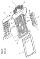
- Fig. 1 is a schematic exploded perspective view showing a junction box which is a first embodiment of the present invention.
- Fig. 2 is a bottom view of a lower case of the junction box of Fig. 1.
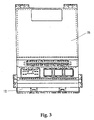
- Fig. 3 is a plan view of an upper case of the junction box of Fig. 1.
- Fig. 4 is a sectional view of the junction box of Fig. 1 in its assembled state.
- Fig. 5 is a side view of the junction box of Fig. 1 showing a fuse module.
- Fig. 6A is a partial side view of a connector module of the junction box of Fig. 1.
- Fig. 6B is a schematic sectional view of the connector module of Fig. 6A.
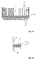
- Fig. 7A is a schematic and partial enlarged sectional view of the fuse module of Fig. 5.
- Fig. 7B is a schematic exploded perspective view of the mount of a fuse in the fuse module of Figs. 5 and 7A.
- Fig. 8 is a partial sectional view of the connection of a relay and a bus bar of the relay module of the junction box of Fig. 1 connected to each other.
- Fig. 9A shows how bus bars to be connected to the load application side output terminals of fuses of the fuse module of the junction box of Fig. 1 are formed from a conductive metal sheet (Figs. 9 to 11 relate to an arrangement of the bus bars of the fuse module modified from that of Fig. 7).
- Fig. 9B shows the positions of the bus bars of Fig. 9A and the fuses and welding tabs of the connector module in the assembled state.
- Fig. 10A shows how bus bars to be connected to the power supply side input terminals of the fuses of the fuse module of the box of Fig. 1 are formed from a conductive metal sheet.
- Fig. 10B shows the positions of the bus bars of Fig. 10A moved after the conductive metal sheet is punched.
- Fig. 10C shows the positions of the bus bars of Fig. 10A and the fuses and welding tabs of the connector module in the assembled state.
- Fig. 11 shows another method by which the bus bars of Fig. 10A are taken out of a conductive metal sheet.
- Fig. 12 is a sectional view of a junction box which is a second embodiment of the present invention.
- Fig. 13 is a schematic view showing bus bar connections in a modified embodiment of the invention.
- Fig. 14 is an exploded perspective view showing a known junction box which is described above.
-
- Fig. 1 shows a
junction box 10 adapted to be connected to at least one wire harness for a vehicle and comprising aconnector module 11, afuse module 12, arelay module 13, alower case 14, anupper case 15 and anelectronic control unit 16. The upper andlower cases fuse module housing 32 are of moulded plastics material. - The
relay module 13, theconnector module 11 and theelectronic control unit 16 are sequentially stacked on thelower case 14 and shown horizontal in the drawings, though the orientation of the box in use may be different. Theupper case 15 is mounted on them. A fusemodule accommodation region 15a is formed at one side as an opening of the peripheral walls between thelower case 14 and theupper case 15. Fuses 30 (see Figs. 4 and 5) are in use mounted on thefuse module 12 from one side thereof. Thefuse module 12 is disposed upright in the fusemodule accommodation region 15a. Relays 40 mounted in use on the lower surface of therelay module 13 are exposed to the outside through openings formed in thelower case 14. A plurality of connector accommodation portions in the form ofsockets 14a which in use receive connectors (not shown) to be connected to theconnector module 11 are formed on the lower surface of thelower case 14. - As shown in Fig. 4, the
connector module 11 is constructed of a plurality ofcircuit structures 23, layered one upon another, each having aninsulation plate 22 andbus bars 21 forming a circuit having a required configuration fixed to theinsulation plate 22. The bus bars 21 are formed from conductive metal sheet.Tabs 21a projecting at ends of the bus bars 21 of each of thecircuit structures 23 project into theconnector sockets 14a of thelower case 14. The connectors (not shown) mounted on an end of a wire harness are fitted in theconnector sockets 14a to connect their terminals to thetabs 21c of theconnector module 11. - As shown in Figs. 6A and 6B, at one side edge of the
connector module 11 opposed to thefuse module 12, a plurality ofwelding tabs bus bars 21 upward and downward in an L-shape are arranged collectively in respective linear rows. A long andnarrow opening 11a for receivingintermediate tabs 13a (described later) projecting from therelay module 13 is formed at a position near the centre of theconnector module 11 parallel to the rows oftabs Tabs 21d to be connected to theintermediate tabs 13a of therelay module 13 are formed in a row on theconnector module 11 along an edge of theopening 11a by bending up ends of selected bus bars 21. - As shown in Figs. 4, 5 and 7A the
fuse module 12 which is disposed upright and adjacent one side edge of theconnector module 11 has ahousing 32 within thecases fuse receiving sockets fuse module 12 of Fig. 7A there is a singlevertical insulation substrate 31. - Inside the
housing 32, bus bars 35, 36, 37 and 38 which are bent to provide pairs of slottedpressure connection terminals fuse receiving sockets insulation substrate 31 in two rows. In use thepressure connection terminals side input terminal 30a and a load applicationside output terminal 30b of each of thefuses 30 which project into thesockets 33 of the upper row (first row) and thesockets 34 of the lower row (second row). Thefuses 30 are arranged vertically. As explained below, the upper row has the bus bars 35, 36 and the lower row has the bus bars 37, 38. - The bus bars 35, 36 of the first (upper) row are bent upward so that welding
tabs fuse module 12 are formed on the upper ends of the bus bars 35, 36 respectively and lie in a linear row projecting from the upper side of thehousing 32 and extending in the longitudinal direction thereof. - The bus bars 37, 38 of the second (lower) row are bent downward so that
welding tabs fuse module 12 are formed on the lower ends of the bus bars 37, 38 respectively and are arranged in a linear row projecting from the lower side of thehousing 32 and extending in the longitudinal direction thereof. - In the
fuse module 12 shown in Fig. 7A, the bus bars 35 - 38 are on asingle insulation substrate 31, so that it is necessary to shape and bend bus bars as shown forbus bar 38 in Fig. 7B, in order that the two pressure connection terminals 37A, 37B are vertically aligned. Theinsulation substrate 31 may be made by moulding, with the bus bars incorporated by in situ moulding. Alternatively the bus bars may be fixed on one or both surfaces of a pre-formed substrate. In the slightly modifiedfuse module 12 to which Figs. 9 to 11 relate, there are two insulation substrates (not shown), superposed one on another, instead of thesingle substrate 31 of Fig. 7A. This enables the bus bars 35-38 to have a simpler shape. The bus bars 35, 37 are on one substrate and the bus bars 36, 38 on the other substrate. The front substrate (with respect to the fuses 30) has apertures through which the pressure connection terminals project from the rear substrate. - As shown in Figs. 9 and 10, the bus bars 35 - 38 of the
fuse module 12 are formed by punchingconductive metal sheets conductive metal sheet 100. The bus bars 35, 37 as punched from thesheet 100 are arranged such that theterminals welding tabs fuse module 12 face outwardly in opposite directions. The bus bars 35, 37 are spaced in thesheet 100 at regular intervals. After being punched, each of the bus bars 35, 37 is bent at the position shown with bold full lines. - Fig. 9B shows how the load application
side output terminals 30b of thefuses 30 and the bus bars 35, 37 are connected to each other by pressure connection when the bus bars 35, 37 are mounted in thefuse module 12 and also shows the positions where thetabs welding tabs connector module 11 respectively. - Fig. 10A shows how the bus bars 36 of the first row to be connected to the power source side input terminals of the fuses and the bus bars 38 of the second row also to be connected to the power source side input terminals of the fuses are punched from the
conductive metal sheet 100. As punched from thesheet 101 thepressure connection terminals terminals welding tabs welding tabs 36b and that of thewelding tabs 38b are different, and thewelding tabs - Therefore, in forming the bus bars 36, 38 from the
conductive metal sheet 101, theterminals welding tabs sheet 101. - After punching, the bus bars 36, 38 are bent at the positions shown with bold full lines in Fig. 10A, and then the positions of the bus bars 36, 38 are changed as shown in Fig. 8B (as if the bus bars 36, 38 were flat) so that the
pressure welding terminals 36a, 38aa are disposed face to face. - Figs. 7A and 7B show an alternative method of bending the bus bars 37, 38.
- Fig. 10C shows how the power supply
side input terminals 30a of thefuses 30 and the bus bars 36, 38 are connected to each other by pressure connection after the bus bars 36, 38 are mounted in thefuse module 12 and also shows the positions wheretabs welding tabs connector module 11 respectively. - The positions of the
welding tabs 36b of the bus bars 36 and those of thewelding tabs 38b of the bus bars 38 are respectively such that thewelding tabs 36b are interposed among thewelding tabs 35b in their linear row and likewise thewelding tabs 38b are interposed among thewelding tabs 37b in their linear row, as shown in Fig. 5. Thus the length ofbent portions 36c of the bus bars 36 and ofbent portions 38c of the bus bars 38 are greater than the length ofbent portions 35c of the bus bars 35 andbent portions 37c of the bus bars 37 respectively. - As shown in Fig. 9, when the bus bars 36, 38 are formed from the conductive metal sheet, the material of the sheet can be used with minimal waste. This will be illustrated by reference to Fig. 11. Let it be supposed that as shown in Fig. 11, bus bars 36' arranged in a row and bus bars 38' arranged in another row are taken from a conductive metal sheet 101', with the
pressure welding terminals 36a' of the bus bars 36' andpressure welding terminals 38a' of the bus bars 38' confronting each other and withwelding tabs 36b' and 38b' facing outwardly in opposite directions in a developed configuration. In this case, portions of large area of the conductive metal sheet 101' covered with oblique lines in Fig. 11 are wasted. It is necessary to make thewelding tabs 36b', 38b' of the bus bars 36', 38' to be connected to the power supply side input terminals longer than the bus bars 35, 37 to be connected to the load application side output terminals. Thus a large area of the material is wasted and further the width W3 of the conductive metal plate 101' is required to be large. - On the other hand, in the case where the
welding tabs conductive metal sheet 101, as shown in Fig. 10, a small portion thereof is wasted. More specifically, it is possible to make the width W1 of theconductive metal plate 101 less than the width W3 of the conductive metal plate 101' by the length of thewelding tab 36b' (38b'). Thus it is possible to make the width W1 of theconductive metal sheet 101 for the bus bars to be connected to the power supply side input terminals almost equal to the width W2 of theconductive metal sheet 100 for the bus bars to be connected to the load application side output terminals. The bus bars can be easily produced at low cost. - Fig. 4 shows a
cover 39 for thefuses 30, fitting on thecases - As shown in Figs. 1 and 4, the
relay module 13 is disposed below theconnector module 11 and at a position proximate to the side where thefuse module 12 is arranged. Bus bars 41 are mounted on asubstrate 42 of therelay module 13. As shown in Fig. 8 the body of therelay 40 engages the lower surface of thesubstrate 42. A terminal 40a of therelay 40 is inserted intoopenings bus bar 41 and thesubstrate 42 respectively and welded to thebus bar 41 withsolder 43. Thus, the terminal 40a of therelay 40 is joined with the relay module directly and permanently. Alternatively, detachable pressure connection terminals may be provided on the relays and the bus bars 41. - One end of the
bus bar 41 welded to the terminal 40a of therelay 40 is bent to project upward at the right end of thesubstrate 42 as seen in Fig. 4 to form theintermediate tab 13a of therelay module 13 confronting theintermediate tab 21d of theconnector module 11. Other bus bars of therelay module 13 are bent up in the same way. The other ends of respective bus bars 41 are bent down and aligned in confrontation with thewelding tabs 21c of theconnector module 11 at the left end of thesubstrate 42 to formwelding tabs 40b of therelay module 13. - As shown in Fig. 4, the
electronic control unit 16 has electronic parts (not shown) mounted on the upper surface of asubstrate 50. Theelectronic control unit 16 is placed on asupport 51 projecting from the upper surface of theconnector module 11 and fixed to an upper portion of theconnector module 11 with a screw 52. In this state, the electronic parts are disposed in a space S disposed between thesubstrate 50 and theupper case 15. - Printed electrical conductors are arranged at one edge of the
substrate 50. The vertically extending bus bar-shaped relayingterminals 53 and the electrical conductors are connected to each other via an ECU connector or directly. The lower end of therelay terminals 53 are connected tobus bars 21 of theconnector module 11. - To assemble the
junction box 10 composed of the above-described component parts, therelay module 13, theconnector module 11 and theelectronic control unit 16 are mounted one upon another sequentially. Then the electrical conductors of theelectronic control unit 16 are connected to the bus bars 21 of theconnector module 11 through therelay terminals 53. Thereafter, with theconnector module 11 and therelay module 13 layered on each other, theintermediate tabs 13a of therelay module 13 projected through theopening 11a of theconnector module 11 and the confrontingintermediate tabs 21d of theconnector module 11 are joined with each other by a suitable welding technique. - The
fuse module 12 is placed at a predetermined position, with thewelding tabs fuse module 12 confronting thewelding tabs connector module 11. Thewelding tabs connector module 11 and thewelding tabs fuse module 12 arranged in rows are sequentially welded to each other. At the lower side, in this welding, thewelding tabs 21c of theconnector module 11 and thewelding tabs fuse module 12 are also layered on thepressure welding tabs 40b of therelay module 13. More specifically, with thewelding tab 21c of theconnector module 11 sandwiched between thepressure welding tab 40b of therelay module 13 and thewelding tab fuse module 12, these three tabs are welded to each other. As desired,pressure welding tab 40b of therelay module 13 and awelding tab fuse module 12 may be welded to each other directly. - In connecting the
connector module 11, thefuse module 12 and therelay module 13 to one another, the welding tabs of theconnector module 11, the welding tabs of thefuse module 12 and the welding tabs of therelay module 13 are arranged linearly along one side of thefuse module 12. Thus the welding operation can be accomplished efficiently. Resistance welding of these tabs is preferred but any suitable welding method may be employed. - After completion of this welding operation, the
connector module 11, thefuse module 12, therelay module 13 and theelectronic control unit 16 joined with each other are fixedly disposed between thelower case 14 and theupper case 15. - Fig. 12 shows a junction box 10' of a second embodiment in which a relay module 13' is disposed above a connector module 11', and an electronic control unit 16' is disposed between the connector module 11' and the relay module 13'. In this case,
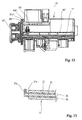
welding tabs 40b' of the relay module 13',upper welding tabs 34b' of the fuse module 12', andwelding tabs 21b' of the connector module 11' are welded to each other. The other features of the construction of the second embodiment correspond to those of the first embodiment, and need not be described again. - Fig. 13 shows a feature of a modified embodiment in which a
tab 21x which is a part of the welding tab of theconnector module 11 projecting from onecircuit structure 23 of theconnector module 11 is welded to awelding tab 21y projecting from anothercircuit structure 23, with thewelding tabs welding tabs such welding tabs welding tabs - As apparent from the foregoing description, in the junction box of the present invention, the welding tabs of the connector module, those of the fuse module or/and those of the relay module are arranged collectively in one or more linear rows at one side of the connector module or intermediately. Thus the welding work for connecting these modules to each other can be performed efficiently. Accordingly, it is possible to reduce the number of steps in assembling the junction box and thus reduce the manufacturing cost. Further because the welding portions can be collectively disposed, it is possible to make the junction box compact. Furthermore in the case where the welding tabs of the connector module, the fuse module and the relay module are layered triply on each other, it is possible to make the number of welding operations much smaller than the case in which the welding portions are separately disposed. Thus it is possible to enhance the efficiency.
- Because the connector connection bus bars, the fuse connection bus bars, and the relay connector connection bus bars are separately provided on the respective modules, tabs to be connected to connectors, fuses and relays are disposed in different positions and do not overlap each other. Consequently it is unnecessary to increase the number of layers of bus bars to form tabs. This makes it possible for the junction box to be compact.
- Further when the specification of any one the connector module, the fuse module and the relay module is altered, it is necessary to alter only one of them. That is, it is unnecessary to alter the entire construction of the junction box. Therefore it is possible to cope with the alteration of the specification in a short time and at a low cost.
- While the invention has been described in conjunction with the exemplary embodiments described above, many equivalent modifications and variations will be apparent to those skilled in the art when given this disclosure. Accordingly, the exemplary embodiments of the invention set forth above are considered to be illustrative and not limiting. Various changes to the described embodiments may be made without departing from the spirit and scope of the invention.
Claims (11)
- An electrical junction box having
a connector module (11) providing a connector connection circuit which in use makes electrical connection to at least one electrical connector,
a fuse module (12) providing a fuse connection circuit which in use makes electrical connection to a plurality of fuses (30), and
a relay module (13) providing a relay connection circuit which in use makes electrical connection to a plurality of relays (40),
said connector module (11) comprising a plurality of insulation substrates (22) stacked one on another to form a layered assembly having a pair of main faces and a plurality of sides, and bus bars (21) fixed on said insulation substrates, said bus bars (21) providing a plurality of projecting first welding tabs (21b, 21c) which are aligned with one another in at least one linear row adjacent one of said sides of said layered assembly,
said fuse module (12) comprising one or more insulation substrates (31) and bus bars (35 - 38) fixed thereon and arranged to be connected in use to said fuses and providing a plurality of projecting second welding tabs (35b - 38b) confronting said first welding tabs (21b, 21c) of said connector module,
said relay module (13) comprising one or more insulation substrates (42) and bus bars (41) fixed thereon and arranged to be connected in use to said relays and providing a plurality of third welding tabs (40b) also confronting said first welding tabs (21b, 21c) of said connector module,
said second and third welding tabs (35b - 38b, 40b) being welded to said first welding tabs (21b, 21c) to effect electrical connection of said connector connection circuit, said fuse connection circuit and said relay connection circuit. - An electrical connection box according to claim 1, having a casing having upper and lower casing parts (14, 15),
wherein said connector module (11), said fuse module (12) and said relay module (13) are mounted in said casing with said layered assembly of said connector module lying horizontally and said insulation substrate or substrates (31) of said fuse module extending vertically, said fuse module being adapted to receive said fuses (30) in use in an upper row and a lower row,
said casing having a lateral opening (15a) for insertion and removal of said fuses,
said first welding tabs (21b, 21c) of said connector module being arranged in a vertically spaced pair of said linear rows,
said second welding tabs (35b - 38b) of said fuse module projecting in a pair of linear rows at an upper side and a lower side respectively of said insulation substrate or substrates (31) of said fuse module and confronting said first welding tabs (21b, 21c) of said pair of linear rows thereof,
said confronting first welding tabs and second welding tabs being welded to each other at said upper and lower sides of said insulation substrate or substrates of said fuse module. - An electrical junction box according to claim 1, wherein said relay module (13) is mounted adjacent one of said main faces of said layered assembly of said connector module (11) and adjacent said fuse module (12), and said third welding tabs (40b) of said relay assembly confront and are welded to both said first welding tabs (21b, 21c) and said second welding tabs (35b - 38b).
- An electrical junction box according to claim 1, having an electronic control unit (16') disposed between said connector module (11') and said relay module (13').
- An electrical junction box according to claim 1, wherein said bus bars (21) of said connector module provide a plurality of fourth welding tabs (21x, 21y) which project from said insulation substrates of said connector module and are welded to each other to effect electrical connections within said connector module.
- An electrical junction box having
a connector module (11) providing a connector connection circuit which in use makes electrical connection to at least one electrical connector, and
a fuse module (12) providing a fuse connection circuit which in use makes electrical connection to a plurality of fuses (30),
said connector module (11) comprising a plurality of insulation substrates (22) stacked one on another to form a layered assembly having a pair of main faces and a plurality of sides, and bus bars (21) fixed on said insulation substrates, said bus bars (21) providing a plurality of projecting first welding tabs (21b, 21c) adjacent one of said sides of said layered assembly,
said fuse module (12) comprising one or more insulation substrates (31) and bus bars (35 - 38) fixed thereon and arranged to be connected in use to said fuses and providing a plurality of projecting second welding tabs (35b - 38b),
said connector module and said fuse module being mutually disposed so that said insulation substrate or substrates (31) of said fuse module are perpendicular to said main faces of said layered assembly of said connector module,
said fuse module having a housing (32) having a plurality of fuse receiving locations (33, 34) arranged in two parallel rows extending in a longitudinal direction parallel to said main faces of said layered assembly of said connector module,
said bus bars (35 - 38) of said fuse module having pressure connection terminals (35a - 38a) located in said fuse receiving locations to engage said fuses,
wherein in said fuse module(i) said bus bars (35, 36) thereof providing said pressure connection terminals (35a, 36a) of a first one of said rows of said fuse receiving locations have welding tabs (35b, 36b) projecting from said insulation substrate or substrates (31) thereof at a first side thereof and arranged in a linear row and welded to a first array of said first welding tabs (21b) of said bus bars of said connector module, and(ii) said bus bars (37, 38) thereof providing said pressure connection terminals (37a, 38a) of the second one of said rows of said fuse receiving locations having welding tabs (37b, 38b) projecting from said insulation substrate or substrates (31) thereof at a second side thereof opposite said first side thereof and arranged in a linear row and welded to a second array of said first welding tabs (21c) of said bus bars of said connector module. - An electrical junction box according to claim 6, wherein said first welding tabs (21b, 21c) of said connector module are formed of projecting portions of said bus bars thereof which are bent so that said first welding tabs are arranged in two linear rows projecting in two opposite directions respectively, which two linear rows extend parallel to said longitudinal direction of said fuse module and constitute respectively said first and second arrays of said first welding tabs confronting, and welded to, said linear rows of said welding tabs of said fuse module.
- An electrical junction box according to claim 7, wherein in each of said rows (33, 34) of said fuse receiving locations of said fuse module, a plurality of said pressure connection terminals (36a, 38a) which constitute power supply side input terminals for said fuses are disposed in a row at a first side of the respective row of fuse receiving locations adjacent the other of said rows of fuse receiving locations, and a plurality of said pressure connection terminals (35a, 37a) which constitute load application side output terminals for said fuses are disposed in a row at a second side of the respective row of fuse receiving locations distal from the other of said rows of fuse receiving locations.
- A method of forming bus bars (35 - 38) for mounting on one or more insulation substrates (31) of a fuse module (12) of an electrical junction box which fuse module is in use adapted to receive a plurality of fuses (30) in two adjacent parallel rows, each said bus bar having at one end at least one pressure connection terminal (35a - 38a) for engaging a fuse terminal in use and at a second end at least one welding tab (35b - 38b), said method of forming said bus bars comprising the steps of(i) punching first ones (35, 37) of said bus bars from a first conductive metal sheet (100) in developed form, the areas of said first sheet providing the respective first bus bars being located in first and second rows in said first sheet such that as punched said pressure connection terminals (35a) of said first bus bars of said first row are opposed to and directed towards said pressure connection terminals (37a) of said first bus bars of said second row while said welding tabs (35b, 37b) of said first bus bars of said first and second rows respectively are outwardly directed in opposite directions away from each other whereby said first bus bars as punched are mutually disposed in the same directions as in their arrangement when mounted on said insulation substrate or substrates (31),(ii) punching second ones (36, 38) of said bus bars from a second conductive metal sheet (101) in developed form, the areas of said second sheet providing said second bus bars being located in third and fourth rows in said second sheet such that as punched said pressure connection terminals (36a, 38a) of said second bus bars of said third and fourth rows respectively are mutually outwardly directed in opposite directions away from each other while said welding tabs (36b, 38b) of said second bus bars of said third and fourth rows are interdigitally arranged alongside each other, and(iii) after punching said second bus bars (36, 38) from said second sheet, said second bus bars of said third and fourth rows respectively are mutually shifted to bring said pressure connection terminals (36a, 38a) thereof into position opposed to and adjacent each other, so that they are mutually disposed in the same directions as in their arrangement when mounted on said insulation substrate or substrates (31).
- A method of making a fuse module (12) for an electrical junction box which fuse module is in use adapted to receive a plurality of fuses in two adjacent parallel rows, comprising the steps of:wherein each said bus bar has at one end at least one pressure connection terminal (35a - 38a) for engaging a fuse terminal in use and at a second end at least one welding tab (35b - 38b), and said step (a) of forming said bus bars comprises:(a) forming bus bars (35 - 38) and(b) mounting said bus bars in a predetermined arrangement on one or more insulation substrates (31),(i) punching first ones (35, 37) of said bus bars from a first conductive metal sheet (100) in developed form, the areas of said first sheet providing the respective first bus bars being located in first and second rows in said first sheet such that as punched said pressure connection terminals (35a) of said first bus bars of said first row are opposed to and directed towards said pressure connection terminals (37a) of said first bus bars of said second row while said welding tabs (35b, 37b) of said first bus bars of said first and second rows respectively are outwardly directed in opposite directions away from each other whereby said first bus bars as punched are mutually disposed in the same directions as in their arrangement when mounted on said insulation substrate or substrates (31),(ii) punching second ones (36, 38) of said bus bars from a second conductive metal sheet (101) in developed form, the areas of said second sheet providing said second bus bars being located in third and fourth rows in said second sheet such that as punched said pressure connection terminals (36a, 38a) of said second bus bars of said third and fourth rows respectively are mutually outwardly directed in opposite directions away from each other while said welding tabs (36b, 38b) of said second bus bars of said third and fourth rows are interdigitally arranged alongside each other, and(iii) after punching said second bus bars (36, 38) from said second sheet, said second bus bars of said third and fourth rows respectively are mutually shifted to bring said pressure connection terminals (36a, 38a) thereof into position opposed to and adjacent each other, so that they are mutually disposed in the same directions as in their arrangement when mounted on said insulation substrate or substrates (31).
- A method according to claim 10, including the step of bending said bus bars (35 - 38), after punching, so that said pressure connection terminals (35a - 38a) thereof extend perpendicularly to said welding tabs (35b - 38b) thereof.
Applications Claiming Priority (6)
| Application Number | Priority Date | Filing Date | Title |
|---|---|---|---|
| JP2000361263A JP3678138B2 (en) | 2000-11-28 | 2000-11-28 | Junction box |
| JP2000361263 | 2000-11-28 | ||
| JP2000377476 | 2000-12-12 | ||
| JP2000377125 | 2000-12-12 | ||
| JP2000377476A JP3757792B2 (en) | 2000-12-12 | 2000-12-12 | Junction box |
| JP2000377125A JP3685059B2 (en) | 2000-12-12 | 2000-12-12 | Method for forming bus bar of fuse module |
Publications (2)
| Publication Number | Publication Date |
|---|---|
| EP1209036A2 true EP1209036A2 (en) | 2002-05-29 |
| EP1209036A3 EP1209036A3 (en) | 2003-11-19 |
Family
ID=27345282
Family Applications (1)
| Application Number | Title | Priority Date | Filing Date |
|---|---|---|---|
| EP01309933A Withdrawn EP1209036A3 (en) | 2000-11-28 | 2001-11-27 | Electrical junction box for a vehicle |
Country Status (2)
| Country | Link |
|---|---|
| US (1) | US6514091B2 (en) |
| EP (1) | EP1209036A3 (en) |
Cited By (3)
| Publication number | Priority date | Publication date | Assignee | Title |
|---|---|---|---|---|
| EP2192006A1 (en) * | 2008-11-27 | 2010-06-02 | Tyco Electronics AMP Korea Ltd. | Junction box for a vehicle |
| EP2224565A1 (en) * | 2007-12-21 | 2010-09-01 | Yazaki Corporation | Mounting structure for plate-like terminals |
| CN104299866A (en) * | 2013-07-15 | 2015-01-21 | 德尔福技术有限公司 | Vehicle electrical center |
Families Citing this family (23)
| Publication number | Priority date | Publication date | Assignee | Title |
|---|---|---|---|---|
| JP4097388B2 (en) * | 2000-07-21 | 2008-06-11 | 住友電装株式会社 | Junction box assembly method and junction box assembled by the method |
| EP1586488A1 (en) * | 2000-10-26 | 2005-10-19 | Sumitomo Wiring Systems, Ltd. | Electrical junction box for a vehicle |
| JP2002330525A (en) * | 2001-04-27 | 2002-11-15 | Yazaki Corp | Junction box |
| DE10162443A1 (en) * | 2001-12-19 | 2003-07-03 | Bayer Ag | Process for the production of dielectric layers using multifunctional carbosilanes |
| JP3954915B2 (en) * | 2002-05-29 | 2007-08-08 | 矢崎総業株式会社 | Electrical junction box and manufacturing method thereof |
| JP2004080917A (en) * | 2002-08-19 | 2004-03-11 | Sumitomo Wiring Syst Ltd | Junction box |
| JP2004159478A (en) * | 2002-11-08 | 2004-06-03 | Sumitomo Wiring Syst Ltd | Junction box |
| JP4126240B2 (en) * | 2003-03-17 | 2008-07-30 | 矢崎総業株式会社 | Circuit board assembly structure |
| JP4077346B2 (en) * | 2003-03-17 | 2008-04-16 | 矢崎総業株式会社 | Electrical connection box busbar connection structure |
| JP4413724B2 (en) * | 2003-12-11 | 2010-02-10 | アンデン株式会社 | Relay device |
| JP4381845B2 (en) * | 2004-02-19 | 2009-12-09 | 株式会社オートネットワーク技術研究所 | Fuse module |
| KR200358267Y1 (en) * | 2004-03-20 | 2004-08-06 | 영화테크(주) | A unification electronic module structure in car |
| JP4304111B2 (en) * | 2004-04-06 | 2009-07-29 | 株式会社オートネットワーク技術研究所 | Electrical junction box |
| JP3879750B2 (en) * | 2004-07-13 | 2007-02-14 | 住友電装株式会社 | Electrical junction box |
| WO2006011478A1 (en) * | 2004-07-27 | 2006-02-02 | Autonetworks Technologies, Ltd. | Electric connection box |
| US8570699B2 (en) * | 2005-04-22 | 2013-10-29 | Lear Corporation | Relayless and fuseless junction box |
| US7459630B2 (en) * | 2006-10-05 | 2008-12-02 | Lear Corporation | Junction box assembly |
| JP2008182797A (en) * | 2007-01-23 | 2008-08-07 | Sumitomo Wiring Syst Ltd | Electrical connection box for mobile |
| US7875820B2 (en) * | 2007-08-22 | 2011-01-25 | Honeywell International Inc. | Switching device having welding tabs for securing sensing structures to the device housing |
| JP5088427B2 (en) * | 2011-03-02 | 2012-12-05 | 第一精工株式会社 | Electrical connector and electrical connector assembly |
| CN109131164B (en) * | 2018-10-24 | 2023-10-20 | 华霆(合肥)动力技术有限公司 | Electric control assembly and system of electric automobile |
| US10763629B1 (en) * | 2019-08-12 | 2020-09-01 | Lear Corporation | Integrated assembly of an electrical conductor, a fuse and a connector |
| US11936128B2 (en) | 2021-02-09 | 2024-03-19 | Lear Corporation | Electrical unit with offset terminals |
Citations (2)
| Publication number | Priority date | Publication date | Assignee | Title |
|---|---|---|---|---|
| JP2000112691A (en) | 1998-10-07 | 2000-04-21 | Seiko Epson Corp | Network printing system, network printer and network printing method |
| EP1145914A2 (en) | 2000-04-13 | 2001-10-17 | Sumitomo Wiring Systems, Ltd. | Electrical junction box |
Family Cites Families (11)
| Publication number | Priority date | Publication date | Assignee | Title |
|---|---|---|---|---|
| US3744129A (en) * | 1972-02-09 | 1973-07-10 | Rogers Corp | Method of forming a bus bar |
| US4381423A (en) * | 1981-03-31 | 1983-04-26 | Rogers Corporation | High capacitance bus bar manufacturing technique |
| US4689718A (en) * | 1986-04-04 | 1987-08-25 | United Technologies Automotive, Inc. | Programmable junction box |
| JP2744932B2 (en) * | 1988-02-24 | 1998-04-28 | 矢崎総業株式会社 | Circuit forming method by busbar |
| US5067905A (en) * | 1989-06-09 | 1991-11-26 | Yazaki Corporation | Electric connection box |
| FR2690601B1 (en) * | 1992-04-22 | 2002-02-01 | Valeo Electronique | Service board for controlling and / or supplying electrical components to vehicles. |
| JP2953335B2 (en) * | 1995-02-14 | 1999-09-27 | 住友電装株式会社 | Branch junction box |
| DE69734095T2 (en) * | 1996-10-24 | 2006-07-13 | Thomas & Betts International Inc., Sparks | POWER DISTRIBUTION UNIT |
| JP3355146B2 (en) * | 1999-03-11 | 2002-12-09 | 株式会社オートネットワーク技術研究所 | Circuit connection structure in junction block |
| US6270260B1 (en) * | 1999-11-19 | 2001-08-07 | A.O. Smith Corporation | Anti-rotational bearing device |
| JP4097392B2 (en) * | 2000-08-09 | 2008-06-11 | 住友電装株式会社 | Junction box and assembly method of junction box |
-
2001
- 2001-11-27 EP EP01309933A patent/EP1209036A3/en not_active Withdrawn
- 2001-11-27 US US09/993,559 patent/US6514091B2/en not_active Expired - Lifetime
Patent Citations (2)
| Publication number | Priority date | Publication date | Assignee | Title |
|---|---|---|---|---|
| JP2000112691A (en) | 1998-10-07 | 2000-04-21 | Seiko Epson Corp | Network printing system, network printer and network printing method |
| EP1145914A2 (en) | 2000-04-13 | 2001-10-17 | Sumitomo Wiring Systems, Ltd. | Electrical junction box |
Cited By (6)
| Publication number | Priority date | Publication date | Assignee | Title |
|---|---|---|---|---|
| EP2224565A1 (en) * | 2007-12-21 | 2010-09-01 | Yazaki Corporation | Mounting structure for plate-like terminals |
| EP2224565A4 (en) * | 2007-12-21 | 2012-01-25 | Yazaki Corp | Mounting structure for plate-like terminals |
| EP2192006A1 (en) * | 2008-11-27 | 2010-06-02 | Tyco Electronics AMP Korea Ltd. | Junction box for a vehicle |
| CN104299866A (en) * | 2013-07-15 | 2015-01-21 | 德尔福技术有限公司 | Vehicle electrical center |
| EP2826673A1 (en) * | 2013-07-15 | 2015-01-21 | Delphi Technologies, Inc. | Vehicle electrical center |
| US9616829B2 (en) | 2013-07-15 | 2017-04-11 | Delphi Technologies, Inc. | Vehicle electrical center |
Also Published As
| Publication number | Publication date |
|---|---|
| US20020064975A1 (en) | 2002-05-30 |
| EP1209036A3 (en) | 2003-11-19 |
| US6514091B2 (en) | 2003-02-04 |
Similar Documents
| Publication | Publication Date | Title |
|---|---|---|
| US6514091B2 (en) | Electrical junction box for a vehicle | |
| EP1201505B1 (en) | Electrical junction box for a vehicle | |
| US6506060B2 (en) | Electrical junction box | |
| EP1530411B1 (en) | Circuit assembly, producing method of the same, distribution unit and bus bar substrate | |
| US20050111166A1 (en) | Circuit assembly and heat-insulating member for circuit assembly | |
| US6511331B2 (en) | Electrical junction box for a vehicle | |
| US20010049877A1 (en) | Method for manufacturing linkage terminal | |
| JP2001045633A (en) | Electrical junction box | |
| JP3678138B2 (en) | Junction box | |
| JP3757792B2 (en) | Junction box | |
| JP3307340B2 (en) | Circuit board and electrical junction box containing the circuit board | |
| JP3685059B2 (en) | Method for forming bus bar of fuse module | |
| JP3736342B2 (en) | Method for forming junction box and connector module | |
| JP3685038B2 (en) | Junction box | |
| JP3736341B2 (en) | Method for forming circuit board to be accommodated in junction box and junction box for accommodating circuit board | |
| JP3685036B2 (en) | Junction box | |
| EP1209037A2 (en) | Electrical junction box for a vehicle | |
| JP3685045B2 (en) | Junction box | |
| JP3695322B2 (en) | Junction box | |
| JP3747777B2 (en) | Junction box | |
| JP3685040B2 (en) | Junction box and method of forming the junction box | |
| JP2000125446A (en) | Wiring board and electrical junction box equipped with the wiring board | |
| JP2005278285A (en) | Electric junction box | |
| JP2003087939A (en) | Junction box |
Legal Events
| Date | Code | Title | Description |
|---|---|---|---|
| PUAI | Public reference made under article 153(3) epc to a published international application that has entered the european phase |
Free format text: ORIGINAL CODE: 0009012 |
|
| 17P | Request for examination filed |
Effective date: 20011217 |
|
| AK | Designated contracting states |
Kind code of ref document: A2 Designated state(s): AT BE CH CY DE DK ES FI FR GB GR IE IT LI LU MC NL PT SE TR |
|
| AX | Request for extension of the european patent |
Free format text: AL;LT;LV;MK;RO;SI |
|
| PUAL | Search report despatched |
Free format text: ORIGINAL CODE: 0009013 |
|
| AK | Designated contracting states |
Kind code of ref document: A3 Designated state(s): AT BE CH CY DE DK ES FI FR GB GR IE IT LI LU MC NL PT SE TR |
|
| AX | Request for extension of the european patent |
Extension state: AL LT LV MK RO SI |
|
| STAA | Information on the status of an ep patent application or granted ep patent |
Free format text: STATUS: THE APPLICATION HAS BEEN WITHDRAWN |
|
| 18W | Application withdrawn |
Effective date: 20040113 |