EP1208733A1 - An apparatus for spreading flowable material - Google Patents
An apparatus for spreading flowable material Download PDFInfo
- Publication number
- EP1208733A1 EP1208733A1 EP00125768A EP00125768A EP1208733A1 EP 1208733 A1 EP1208733 A1 EP 1208733A1 EP 00125768 A EP00125768 A EP 00125768A EP 00125768 A EP00125768 A EP 00125768A EP 1208733 A1 EP1208733 A1 EP 1208733A1
- Authority
- EP
- European Patent Office
- Prior art keywords
- vane
- spreading
- disc
- different
- spreader
- Prior art date
- Legal status (The legal status is an assumption and is not a legal conclusion. Google has not performed a legal analysis and makes no representation as to the accuracy of the status listed.)
- Withdrawn
Links
Images


Classifications
-
- A—HUMAN NECESSITIES
- A01—AGRICULTURE; FORESTRY; ANIMAL HUSBANDRY; HUNTING; TRAPPING; FISHING
- A01C—PLANTING; SOWING; FERTILISING
- A01C17/00—Fertilisers or seeders with centrifugal wheels
- A01C17/001—Centrifugal throwing devices with a vertical axis
-
- A—HUMAN NECESSITIES
- A01—AGRICULTURE; FORESTRY; ANIMAL HUSBANDRY; HUNTING; TRAPPING; FISHING
- A01C—PLANTING; SOWING; FERTILISING
- A01C17/00—Fertilisers or seeders with centrifugal wheels
- A01C17/006—Regulating or dosing devices
- A01C17/008—Devices controlling the quantity or the distribution pattern
Definitions
- the present invention relates to an apparatus for spreading flowable material of the kind set forth in the preamble of claim 1.
- An apparatus of this kind is e.g. known from EP-0,880,877.
- This document describes an apparatus comprising at least one container for flowable with at least one outlet opening for the material.
- a spreader disc positioned below said outlet opening is adapted to rotate about a mainly vertical axis in two different directions and the spreader disc is provided with a spreader vane construction having a radial inner part and radial outer part.
- the radial outer end of the radial inner part is offset in such a manner in the radial and tangential direction relative to the radial inner end of the radial outer part that an opening is formed between them, through which the flowable material can pass, when rotating in one of said directions.
- the spreading pattern can be changed, e.g.
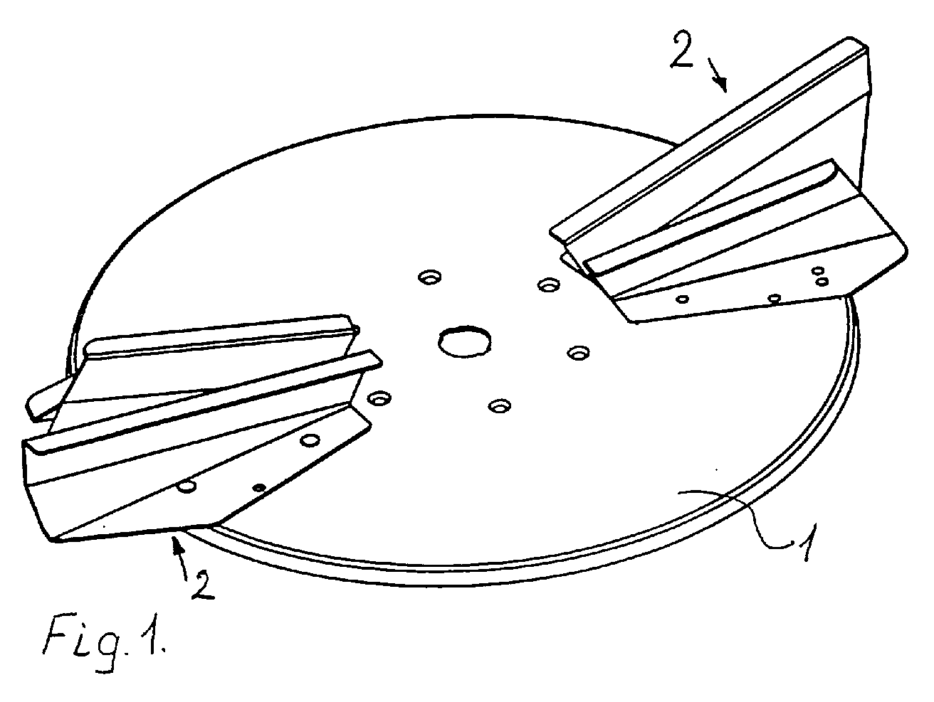
- FIGS 1-3 show different views of a dish-shaped spreader disc 1 adapted to rotate about a generally vertical axis during operation in a first direction 7 or in a second and opposite direction 8, such as will be explained in more detail below.
- the spreader disc 1 carries two spreader vane constructions 2, each of which, as shown in Figures 4 and 5, comprising a first vane part 3 and a second vane part 4 where the first vane part 3 is active and controlling for the spreading when the disc 1 is rotating in the first direction of rotation 7 and the second vane part 4 being active and controlling for the spreading, when the disc is rotating in the second direction of rotation 8.
- a connecting plate 5 is positioned between the first vane part 3 and the second vane part 4 in order to fix the relative position of the two vane parts 3,4, whereby the vane part construction 2 is constructed in one unit for mounting on the spreading disc 1.
- the vane construction 2 is mounted on the spreading disc 1 by means of bolts or rivets 6, or any other suitable mounting means.
- the special feature of the spreader vane construction 2 according to the present invention consists in the fact that the first and second vane parts 3 and 4 are formed mutually independently, whereby the spreading pattern provided by the two vane parts can be formed independently.
- the different spreading patterns are provided by providing an engagement of the two vane parts with the material, which ceases in different radial distance from the axis of rotation, thus providing a different casting distance for the two vane parts 3,4.
- the connecting plate 5 can be positioned at the top of the two vane parts 3,4, thereby covering the interspace between those two vane parts 3,4, whereby the material to be spread is unable to penetrate into the area between the two vane parts 3,4.
- the different constructions of the spreader disc 1 with vane construction 2 are, in a known manner, positioned to receive flowable material, e.g. fertiliser in the form of granules, in a known manner falling down from suitable openings in the bottom of the container.
- flowable material e.g. fertiliser in the form of granules
- the material is thrown outwards by the centrifugal force, possibly assisted by the air current created by the spreader vanes 3,4, until it is intercepted by the vanes and thrown further outwardly from the disc 1 in a spreading pattern which is controlled by the construction of the disc 1 and the vane parts 3,4, whereby the construction of the vane parts 3,4 primarily determine the throwing distance.
Abstract
Description
- The present invention relates to an apparatus for spreading flowable material of the kind set forth in the preamble of
claim 1. - An apparatus of this kind is e.g. known from EP-0,880,877. This document describes an apparatus comprising at least one container for flowable with at least one outlet opening for the material. A spreader disc positioned below said outlet opening is adapted to rotate about a mainly vertical axis in two different directions and the spreader disc is provided with a spreader vane construction having a radial inner part and radial outer part. The radial outer end of the radial inner part is offset in such a manner in the radial and tangential direction relative to the radial inner end of the radial outer part that an opening is formed between them, through which the flowable material can pass, when rotating in one of said directions. With this construction, the spreading pattern can be changed, e.g. with a view to be able to pass along a field boundary or a water course without spreading e.g. fertiliser beyond certain limits, by making the disc rotate in the direction in which the flowable material passes through said opening, whereby a reduced casting distance is obtained. In this construction, the forming of the radial inner part and the radial outer part are, however, mutually dependent and changes of the construction of one of these parts will inevitably influence the spreading patterns for both directions of rotation.
- Based on this prior art, it is the object of the present invention to provide an apparatus of the kind referred to initially, with which it is possible to construct the vane part being active and controlling for the spreading, when the spreader disc is rotating in one direction, independently of the vane part being active and controlling for the spreading when the spreader disc is rotating in the opposite direction, and this object is achieved by the features set forth in the characterizing clause of
claim 1. By so doing, it is possible to change the construction of one vane part without influencing the function of the other vane part. - Preferred embodiments of the apparatus according to the invention are revealed in the sub-ordinate claims in which claims 2-5 indicate different ways of providing different spreading patterns for the two vane parts being active and controlling for the spreading when the spreading disc is rotating in the two different directions, respectively, and claims 6-8 indicate different preferred construction details for the vane parts.
- The present invention will be explained in the following with reference to the drawings, showing an exemplary embodiment of a spreading apparatus according to the invention, of which only the parts necessary for the understanding of the invention are shown, whereas
- Figure 1 shows in perspective as viewed at a skew angle from above, a spreader disc to which two spreader vane constructions according to the invention are secured,
- Figure 2 is a top view of the construction shown in Figure 1,
- Figure 3 is a front view of the construction shown in Figures 1 and 2,
- Figure 4 is a perspective view of the spreader vane construction shown in Figures 1-3, and
- Figure 5 is a view of the spreader vane construction seen in the direction V-V in Figure 2.
-
- The Figures 1-3 show different views of a dish-
shaped spreader disc 1 adapted to rotate about a generally vertical axis during operation in a first direction 7 or in a second and opposite direction 8, such as will be explained in more detail below. - The
spreader disc 1 carries twospreader vane constructions 2, each of which, as shown in Figures 4 and 5, comprising afirst vane part 3 and a second vane part 4 where thefirst vane part 3 is active and controlling for the spreading when thedisc 1 is rotating in the first direction of rotation 7 and the second vane part 4 being active and controlling for the spreading, when the disc is rotating in the second direction of rotation 8. In thevane construction 2 shown in the Figures, a connectingplate 5 is positioned between thefirst vane part 3 and the second vane part 4 in order to fix the relative position of the twovane parts 3,4, whereby thevane part construction 2 is constructed in one unit for mounting on the spreadingdisc 1. Thevane construction 2 is mounted on the spreadingdisc 1 by means of bolts or rivets 6, or any other suitable mounting means. - The special feature of the
spreader vane construction 2 according to the present invention consists in the fact that the first andsecond vane parts 3 and 4 are formed mutually independently, whereby the spreading pattern provided by the two vane parts can be formed independently. In the construction shown in the Figures, the different spreading patterns are provided by providing an engagement of the two vane parts with the material, which ceases in different radial distance from the axis of rotation, thus providing a different casting distance for the twovane parts 3,4. By having the twovane parts 3,4 formed mutually independently, it is also possible to provide the different spreading patterns by having the engagement of the two vane parts with the material initiated in different radial distances from the axis of rotation, due to the fact that the acceleration of the material naturally will be dependent on the distance over which the vane part engages the material. - Other possibilities of providing different spreading patterns for the two
vane parts 3,4 are to provide different angular positions of the vane parts relative to a radial direction or to form the vane parts with different curvature or different friction or different retarding arrangements. - In an alternative embodiment, the connecting
plate 5 can be positioned at the top of the twovane parts 3,4, thereby covering the interspace between those twovane parts 3,4, whereby the material to be spread is unable to penetrate into the area between the twovane parts 3,4. - Another alternative could be to omit the connecting
plate 5, whereby the twovane parts 3,4 are constructed as separate units, each to be mounted on the spreadingdisc 1. - The different constructions of the
spreader disc 1 withvane construction 2 are, in a known manner, positioned to receive flowable material, e.g. fertiliser in the form of granules, in a known manner falling down from suitable openings in the bottom of the container. - In the manner known, the material is thrown outwards by the centrifugal force, possibly assisted by the air current created by the
spreader vanes 3,4, until it is intercepted by the vanes and thrown further outwardly from thedisc 1 in a spreading pattern which is controlled by the construction of thedisc 1 and thevane parts 3,4, whereby the construction of thevane parts 3,4 primarily determine the throwing distance. - By means of the described construction it is possible to control the casting distance for the spreading apparatus by simply changing the direction of rotation of the
disc 1, further control being possible by adjusting the rotational speed of thedisc 1. - Several modifications of the apparatus may be performed without deviating from the following claims, such modifications e.g. comprising further means, such as adjustable screens or guides for controlling the spreading patterns, e.g. of the type known from EP-A2-0,699,377.
Claims (8)
- Apparatus for spreading flowable material comprisinga) at least one container for flowable material and comprising at least one outlet opening for the material,b) a spreader disc (1) positioned below at least one of said outlet openings and adapted to rotate about a mainly vertical axis in a first direction (7) or in a second, opposite direction (8), andc) at least one spreader vane construction (2) secured to the upper side of each spreader disc (1) and comprising a first (3) and second (4) vane part protruding upwardly from the spreader disc (1) and having a not inconsiderable extent in the axial and radial directions, the first vane part (3) being active and controlling for the spreading when the spreader disc is rotating in the first direction (7) and the second vane part (4) being active and controlling for the spreading when the spreader disc is rotating in the second, opposite direction (8), whereby the engagement of the two vane parts (3,4) with the material provides different spreading patterns when the spreader disc is rotating in the first (7) and second, opposite direction (8), respectively, characterized by the engagement surfaces of the two vane parts (3,4) being formed mutually independently.
- Apparatus in accordance with claim 1, characterized by the mutually different spreading patterns being provided by the engagement of the first vane part (3) with the material ceasing in a first radial distance from the axis of rotation and the engagement of the second vane part (4) with the material ceasing in a second radial distance from the axis of rotation, said second distance being different from said first distance.
- Apparatus in accordance with claim 1 or 2, characterized by the mutually different spreading patterns being provided by the engagement of the first vane part (3) with the material being initiated in a first radial distance from the axis of rotation and the engagement of the second vane part (4) with the material being initiated in a second radial distance from the axis of rotation, said second distance being different from said first distance.
- Apparatus in accordance with any of the preceding claims, characterized by the mutually different spreading patterns being provided by the angular position of the first vane part (3) relative to the radial direction on the spreading disc being different from the corresponding angular position of the second vane part (4).
- Apparatus in accordance with any of the preceding claims, characterized by the different spreading patterns being provided by forming the engagement surfaces of the two vane parts (3,4) with different curvature or different friction or different retarding arrangements.
- Apparatus in accordance with any of the preceding claims, characterized by comprising a covering (5) of an interspace between the vane parts (3,4).
- Apparatus in accordance with any of the preceding claims, characterized by the two vane parts (3,4) being constructed in one unit (2) for mounting on the spreading disc (1).
- Apparatus in accordance with any of the claims 1-6, characterized by the two vane parts (3,4) being constructed as separate units, each for mounting on the spreading disc (1).
Priority Applications (1)
| Application Number | Priority Date | Filing Date | Title |
|---|---|---|---|
| EP00125768A EP1208733A1 (en) | 2000-11-24 | 2000-11-24 | An apparatus for spreading flowable material |
Applications Claiming Priority (1)
| Application Number | Priority Date | Filing Date | Title |
|---|---|---|---|
| EP00125768A EP1208733A1 (en) | 2000-11-24 | 2000-11-24 | An apparatus for spreading flowable material |
Publications (1)
| Publication Number | Publication Date |
|---|---|
| EP1208733A1 true EP1208733A1 (en) | 2002-05-29 |
Family
ID=8170473
Family Applications (1)
| Application Number | Title | Priority Date | Filing Date |
|---|---|---|---|
| EP00125768A Withdrawn EP1208733A1 (en) | 2000-11-24 | 2000-11-24 | An apparatus for spreading flowable material |
Country Status (1)
| Country | Link |
|---|---|
| EP (1) | EP1208733A1 (en) |
Cited By (2)
| Publication number | Priority date | Publication date | Assignee | Title |
|---|---|---|---|---|
| EP1721502A1 (en) * | 2005-05-13 | 2006-11-15 | Sulky-Burel S.A.S | Centrifugal spreader for spreading granular and/or pulverulent material |
| EP2014834A2 (en) | 2007-07-09 | 2009-01-14 | Kugelmann, Siegfried | Spinnerdisc for Winterservice-Spreading-Apparatus |
Citations (4)
| Publication number | Priority date | Publication date | Assignee | Title |
|---|---|---|---|---|
| GB2091983A (en) * | 1980-12-24 | 1982-08-11 | Amazonen Werke Dreyer H | A centrifugal spreader |
| EP0104622A2 (en) * | 1982-09-27 | 1984-04-04 | Kuhn S.A. | Spreader for manure, fertiliser and the like |
| DE3917210A1 (en) * | 1989-05-26 | 1990-11-29 | Amazonen Werke Dreyer H | Centrifugal fertiliser distributor mechanism - has ancillary gear connected before distributor gear |
| EP0981939A1 (en) * | 1998-08-26 | 2000-03-01 | A.P. Laursen A/S | Method of spreading flowable material |
-
2000
- 2000-11-24 EP EP00125768A patent/EP1208733A1/en not_active Withdrawn
Patent Citations (4)
| Publication number | Priority date | Publication date | Assignee | Title |
|---|---|---|---|---|
| GB2091983A (en) * | 1980-12-24 | 1982-08-11 | Amazonen Werke Dreyer H | A centrifugal spreader |
| EP0104622A2 (en) * | 1982-09-27 | 1984-04-04 | Kuhn S.A. | Spreader for manure, fertiliser and the like |
| DE3917210A1 (en) * | 1989-05-26 | 1990-11-29 | Amazonen Werke Dreyer H | Centrifugal fertiliser distributor mechanism - has ancillary gear connected before distributor gear |
| EP0981939A1 (en) * | 1998-08-26 | 2000-03-01 | A.P. Laursen A/S | Method of spreading flowable material |
Cited By (4)
| Publication number | Priority date | Publication date | Assignee | Title |
|---|---|---|---|---|
| EP1721502A1 (en) * | 2005-05-13 | 2006-11-15 | Sulky-Burel S.A.S | Centrifugal spreader for spreading granular and/or pulverulent material |
| FR2885482A1 (en) * | 2005-05-13 | 2006-11-17 | Sulky Burel Soc Par Actions Si | CENTRIFUGAL SPREADING DEVICE OF A PULVERULENT OR GRANULAR PRODUCT |
| EP2014834A2 (en) | 2007-07-09 | 2009-01-14 | Kugelmann, Siegfried | Spinnerdisc for Winterservice-Spreading-Apparatus |
| EP2014834A3 (en) * | 2007-07-09 | 2010-11-10 | Kugelmann, Siegfried | Spinnerdisc for Winterservice-Spreading-Apparatus |
Similar Documents
| Publication | Publication Date | Title |
|---|---|---|
| EP1622821B1 (en) | Device for dividing a stream of particulate or pulverulent material into substreams | |
| AU2009302948B2 (en) | A material feeding device for a VSI-crusher, and a method of crushing material. | |
| US9757743B2 (en) | Water rotatable distributor for stream rotary sprinklers | |
| CA1083195A (en) | Spreader for particulate material | |
| EP1545783B1 (en) | A crusher and a method of crushing material | |
| EP1208733A1 (en) | An apparatus for spreading flowable material | |
| CA1316386C (en) | High-consistency pulp tower and method of discharging pulp from the tower | |
| EP0102333B1 (en) | Method and apparatus for spreading and distributing a solid or liquid particulate material | |
| EP0880877B1 (en) | Method of spreading flowable material, apparatus for use in carrying out the method, and spreader vane for use in the apparatus | |
| US4489892A (en) | Apparatus for distributing a substance | |
| EP0101707B1 (en) | Spreader device in a storage container for uniform filling of the container with granular storage goods | |
| CZ342599A3 (en) | Blade ring for pneumatic roller mills | |
| NO180454B (en) | The grating plate for a sprinkler for spreading current mass | |
| US5829698A (en) | Rotor design | |
| EP1145614B1 (en) | Apparatus for distributing particulate fertilizer | |
| EP0183292B1 (en) | A spreader | |
| JP4555993B2 (en) | Fertilizer spreader | |
| US4462550A (en) | Apparatus for distributing a substance | |
| EP0238153B1 (en) | A spreader for spreading granular and/or powdery matrial | |
| JPH03407Y2 (en) | ||
| US3133737A (en) | Spreader for artificial fertilizers and other granular material | |
| SU1752234A1 (en) | Spreading member of mineral fertilizer applicator | |
| US5511369A (en) | Chute to prevent clumping of grass ejected from a mower | |
| GB2174882A (en) | A spreader | |
| KR200237398Y1 (en) | A fertilizer distributor for tractor |
Legal Events
| Date | Code | Title | Description |
|---|---|---|---|
| PUAI | Public reference made under article 153(3) epc to a published international application that has entered the european phase |
Free format text: ORIGINAL CODE: 0009012 |
|
| AK | Designated contracting states |
Kind code of ref document: A1 Designated state(s): AT BE CH CY DE DK ES FI FR GB GR IE IT LI LU MC NL PT SE TR |
|
| AX | Request for extension of the european patent |
Free format text: AL;LT;LV;MK;RO;SI |
|
| 17P | Request for examination filed |
Effective date: 20021129 |
|
| AKX | Designation fees paid |
Designated state(s): DE DK FR GB NL |
|
| 17Q | First examination report despatched |
Effective date: 20050928 |
|
| GRAP | Despatch of communication of intention to grant a patent |
Free format text: ORIGINAL CODE: EPIDOSNIGR1 |
|
| STAA | Information on the status of an ep patent application or granted ep patent |
Free format text: STATUS: THE APPLICATION IS DEEMED TO BE WITHDRAWN |
|
| 18D | Application deemed to be withdrawn |
Effective date: 20090106 |