EP1208563B1 - Noisy acoustic signal enhancement - Google Patents
Noisy acoustic signal enhancement Download PDFInfo
- Publication number
- EP1208563B1 EP1208563B1 EP00955497A EP00955497A EP1208563B1 EP 1208563 B1 EP1208563 B1 EP 1208563B1 EP 00955497 A EP00955497 A EP 00955497A EP 00955497 A EP00955497 A EP 00955497A EP 1208563 B1 EP1208563 B1 EP 1208563B1
- Authority
- EP
- European Patent Office
- Prior art keywords
- signal
- time
- noise
- frequency representation
- input signal
- Prior art date
- Legal status (The legal status is an assumption and is not a legal conclusion. Google has not performed a legal analysis and makes no representation as to the accuracy of the status listed.)
- Expired - Lifetime
Links
- 238000000034 method Methods 0.000 claims description 47
- 230000001052 transient effect Effects 0.000 claims description 35
- 238000004590 computer program Methods 0.000 claims description 8
- 230000002708 enhancing effect Effects 0.000 claims description 8
- 230000001131 transforming effect Effects 0.000 claims 4
- 230000008569 process Effects 0.000 description 25
- 238000001228 spectrum Methods 0.000 description 19
- 238000010586 diagram Methods 0.000 description 8
- 238000012545 processing Methods 0.000 description 8
- 230000006870 function Effects 0.000 description 7
- 238000001914 filtration Methods 0.000 description 5
- 238000002955 isolation Methods 0.000 description 5
- 230000003595 spectral effect Effects 0.000 description 5
- 238000013459 approach Methods 0.000 description 4
- 230000008901 benefit Effects 0.000 description 4
- 238000004891 communication Methods 0.000 description 4
- 230000009467 reduction Effects 0.000 description 4
- 230000003044 adaptive effect Effects 0.000 description 3
- 238000003491 array Methods 0.000 description 3
- 238000001514 detection method Methods 0.000 description 3
- 230000009466 transformation Effects 0.000 description 3
- 239000000872 buffer Substances 0.000 description 2
- 238000004364 calculation method Methods 0.000 description 2
- 230000015556 catabolic process Effects 0.000 description 2
- 238000006731 degradation reaction Methods 0.000 description 2
- 230000000694 effects Effects 0.000 description 2
- 238000011160 research Methods 0.000 description 2
- 238000012549 training Methods 0.000 description 2
- 239000000654 additive Substances 0.000 description 1
- 230000000996 additive effect Effects 0.000 description 1
- 238000004378 air conditioning Methods 0.000 description 1
- 238000004458 analytical method Methods 0.000 description 1
- 230000003190 augmentative effect Effects 0.000 description 1
- 230000004888 barrier function Effects 0.000 description 1
- 230000008859 change Effects 0.000 description 1
- 230000003750 conditioning effect Effects 0.000 description 1
- 238000013500 data storage Methods 0.000 description 1
- 238000002592 echocardiography Methods 0.000 description 1
- 238000005516 engineering process Methods 0.000 description 1
- 208000016354 hearing loss disease Diseases 0.000 description 1
- 230000003993 interaction Effects 0.000 description 1
- 230000002452 interceptive effect Effects 0.000 description 1
- 239000000203 mixture Substances 0.000 description 1
- 230000003287 optical effect Effects 0.000 description 1
- 230000035515 penetration Effects 0.000 description 1
- 230000000135 prohibitive effect Effects 0.000 description 1
- 238000005070 sampling Methods 0.000 description 1
- 238000000844 transformation Methods 0.000 description 1
Images

Classifications
-
- G—PHYSICS
- G10—MUSICAL INSTRUMENTS; ACOUSTICS
- G10L—SPEECH ANALYSIS TECHNIQUES OR SPEECH SYNTHESIS; SPEECH RECOGNITION; SPEECH OR VOICE PROCESSING TECHNIQUES; SPEECH OR AUDIO CODING OR DECODING
- G10L21/00—Speech or voice signal processing techniques to produce another audible or non-audible signal, e.g. visual or tactile, in order to modify its quality or its intelligibility
- G10L21/02—Speech enhancement, e.g. noise reduction or echo cancellation
- G10L21/0208—Noise filtering
- G10L21/0216—Noise filtering characterised by the method used for estimating noise
- G10L21/0232—Processing in the frequency domain
-
- G—PHYSICS
- G10—MUSICAL INSTRUMENTS; ACOUSTICS
- G10L—SPEECH ANALYSIS TECHNIQUES OR SPEECH SYNTHESIS; SPEECH RECOGNITION; SPEECH OR VOICE PROCESSING TECHNIQUES; SPEECH OR AUDIO CODING OR DECODING
- G10L21/00—Speech or voice signal processing techniques to produce another audible or non-audible signal, e.g. visual or tactile, in order to modify its quality or its intelligibility
- G10L21/02—Speech enhancement, e.g. noise reduction or echo cancellation
- G10L21/0208—Noise filtering
- G10L21/0264—Noise filtering characterised by the type of parameter measurement, e.g. correlation techniques, zero crossing techniques or predictive techniques
-
- H—ELECTRICITY
- H04—ELECTRIC COMMUNICATION TECHNIQUE
- H04R—LOUDSPEAKERS, MICROPHONES, GRAMOPHONE PICK-UPS OR LIKE ACOUSTIC ELECTROMECHANICAL TRANSDUCERS; DEAF-AID SETS; PUBLIC ADDRESS SYSTEMS
- H04R2225/00—Details of deaf aids covered by H04R25/00, not provided for in any of its subgroups
- H04R2225/43—Signal processing in hearing aids to enhance the speech intelligibility
Definitions
- This invention relates to systems and methods for enhancing the quality of an acoustic signal degraded by additive noise.
- Acoustic signals are often degraded by the presence of noise. For example, in a busy office or a moving automobile, the performance of ASR systems degrades substantially. If voice is transmitted to a remote listener - as in a teleconferencing system - the presence of noise can be annoying or distracting to the listener, or even make the speech difficult to understand. People with a loss of hearing have notable difficulty understanding speech in noisy environment, and the overall gain applied to the signal by most current hearing aids does not help alleviate the problem. Old music recordings are often degraded by the presence of impulsive noise or hissing. Other examples of communication where acoustic signal degradation by noise occurs include telephony, radio communications, video-conferencing, computer recordings, etc.
- Continuous speech large vocabulary ASR is particularly sensitive to noise interference, and the solution adopted by the industry so far has been the use of headset microphones.
- Noise reduction is obtained by the proximity of the microphone to the mouth of the subject (about one-half inch), and sometimes also by special proximity effect microphones.
- a user often finds it awkward to be tethered to a computer by the headset, and annoying to be wearing an obtrusive piece of equipment.
- the need to use a headset precludes impromptu human-machine interactions, and is a significant barrier to market penetration of ASR technology.
- adaptive filtering Apart from close-proximity microphones, traditional approaches to acoustic signal enhancement in communication have been adaptive filtering and spectral subtraction.
- a second microphone samples the noise but not the signal. The noise is then subtracted from the signal.
- One problem with this approach is the cost of the second microphone, which needs to be placed at a different location from the one used to pick up the source of interest. Moreover, it is seldom possible to sample only the noise and not include the desired source signal.
- Another form of adaptive filtering applies bandpass digital filtering to the signal. The parameters of the filter are adapted so as to maximize the signal-to-noise ratio (SNR), with the noise spectrum averaged over long periods of time. This method has the disadvantage of leaving out the signal in the bands with low SNR.
- SNR signal-to-noise ratio
- a recent approach to noise reduction has been the use of beamforming using an array of microphones.
- This technique requires specialized hardware, such as multiple microphones, A/D converters, etc ., thus raising the cost of the system. Since the computational cost increases proportionally to the square of the number of microphones, that cost also can become prohibitive.
- Another limitation of microphone arrays is that some noise still leaks through the beamforming process.
- actual array gains are usually much lower than those measured in anechoic conditions, or predicted from theory, because echoes and reverberation of interfering sound sources are still accepted through the mainlobe and sidelobes of the array.
- a noise reduction system based on template matching is known from T F Quatieri et al, "Noise reduction using a soft decision sine-wave vector quantizer", ICASSP'90, pages 821-824, 03-04-1990.
- the inventor has determined that it would be desirable to be able to enhance an acoustic signal without leaving out any part of the spectrum, introducing unnatural noise, or distorting the signal, and without the expense of microphone arrays.
- the present invention provides a system and method for acoustic signal enhancement that avoids the limitations of prior techniques.
- the invention includes a method, apparatus, and computer program to enhance the quality of an acoustic signal by processing an input signal in such a manner as to produce a corresponding output that has very low levels of noise ("signal” is used to mean a signal of interest; background and distracting sounds against which the signal is to be enhanced is referred to as "noise").
- signal is used to mean a signal of interest; background and distracting sounds against which the signal is to be enhanced is referred to as "noise").
- enhancement is accomplished by the use of a signal model augmented by learning.
- the input signal may represent human speech, but it should be recognized that the invention could be used to enhance any type of live or recorded acoustic data, such as musical instruments and bird or human singing.
- the preferred embodiment of the invention enhances input signals as follows: An input signal is digitized into binary data which is transformed to a time-frequency representation. Background noise is estimated and transient sounds are isolated. A signal detector is applied to the transients. Long transients without signal content and the background noise between the transients are included in the noise estimate. If at least some part of a transient contains signal of interest, the spectrum of the signal is compared to the signal model after rescaling, and the signal's parameters are fitted to the data. Low-noise signal is resynthesized using the best fitting set of signal model parameters. Since the signal model only incorporates low noise signal, the output signal also has low noise.
- the signal model is trained with low-noise signal data by creating templates from the spectrograms when they are significantly different from existing templates. If an existing template is found that resembles the input pattern, the template is averaged with the pattern in such a way that the resulting template is the average of all the spectra that matched that template in the past.
- the knowledge of signal characteristics thus incorporated in the model serves to constrict the reconstruction of the signal, thereby avoiding introduction of unnatural noise or distortions.
- the invention has the following advantages: it can output resynthesized signal data that is devoid of both impulsive and stationary noise, it needs only a single microphone as a source of input signals, and the output signal in regions of low SNR is kept consistent with those spectra the source could generate.
- FIG. 1 shows a block diagram of a typical prior art programmable processing system which may be used for implementing the signal enhancement system of the invention.
- An acoustic signal is received at a transducer microphone 10, which generates a corresponding electrical signal representation of the acoustic signal.
- the signal from the transducer microphone 10 is then preferably amplified by an amplifier 12 before being digitized by an analog-to-digital converter 14.
- the output of the analog-to-digital converter 14 is applied to a processing system which applies the enhancement techniques of the invention.
- the processing system preferably includes a CPU 16, RAM 20, ROM 18 (which may be writable, such as a flash ROM), and an optional storage device 22, such as a magnetic disk, coupled by a CPU bus 23 as shown.
- the output of the enhancement process can be applied to other processing systems, such as an ASR system, or saved to a file, or played back for the benefit of a human listener. Playback is typically accomplished by converting the processed digital output stream into an analog signal by means of a digital-to-analog converter 24, and amplifying the analog signal with an output amplifier 26 which drives an audio speaker 28 (e.g., a loudspeaker, headphone, or earphone).
- an audio speaker 28 e.g., a loudspeaker, headphone, or earphone.
- a first functional component of the invention is a dynamic background noise estimator that transforms input data to a time-frequency representation.
- the noise estimator provides a means of estimating continuous or slowly-varying background noise causing signal degradation.
- the noise estimator should also be able to adapt to a sudden change in noise levels, such as when a source of noise is activated ( e . g ., an air-conditioning system coming on or off).
- the dynamic background noise estimation function is capable of separating transient sounds from background noise, and estimate the background noise alone.
- a power detector acts in each of multiple frequency bands. Noise-only portions of the data are used to generate mean and standard-deviation of the noise in decibels (dB). When the power exceeds the mean by more than a specified number of standard deviations in a frequency band, the corresponding time period is flagged as containing signal and is not used to estimate the noise-only spectrum.
- the dynamic background noise estimator works closely with a second functional component, a transient detector.
- a transient occurs when acoustic power rises and then falls again within a relatively short period of time.
- Transients can be speech utterances, but can also be transient noises, such as banging, door slamming, etc . Isolation of transients allow them to be studied separately and classified into signal and non-signal events. Also, it is useful to recognize when a rise in power level is permanent, such as when a new source of noise is turned on. This allows the system to adapt to that new noise level.
- the third functional component of the invention is a signal detector.
- a signal detector is useful to discriminate non-signal non-stationary noise. In the case of harmonic sounds, it is also used to provide a pitch estimate if it is desired that a human listener listens to the reconstructed signal.
- a preferred embodiment of a signal detector that detects voice in the presence of noise is described below.
- the voice detector uses glottal pulse detection in the frequency domain.
- a spectrogram of the data is produced (temporal-frequency representation of the signal) and, after taking the logarithm of the spectrum, the signal is summed along the time axis up to a frequency threshold.
- a high autocorrelation of the resulting time series is indicative of voiced speech.
- the pitch of the voice is the lag for which the autocorrelation is maximum.
- the fourth functional component is a spectral rescaler.
- the input signal can be weak or strong, close or far.
- the measured spectra is rescaled so that the inter-pattern distance does not depend on the overall loudness of the signal.
- weighting is proportional to the SNR in decibels (dB). The weights are bounded below and above by a minimum and a maximum value, respectively.
- the spectra are rescaled so that the weighted distance to each stored template is minimum.
- the fifth functional component is a pattern matcher.
- the distance between templates and the measured spectrogram can be one of several appropriate metrics, such as the Euclidian distance or a weighted Euclidian distance.
- the template with the smallest distance to the measured spectrogram is selected as the best fitting prototype.
- the signal model consists of a set of prototypical spectrograms of short duration obtained from low-noise signal. Signal model training is accomplished by collecting spectrograms that are significantly different from prototypes previously collected. The first prototype is the first signal spectrogram containing signal significantly above the noise. For subsequent time epochs, if the spectrogram is closer to any existing prototype than a selected distance threshold, then the spectrogram is averaged with the closest prototype. If the spectrogram is farther away from any prototype than the selected threshold, then the spectrogram is declared to be a new prototype.
- the sixth functional component is a low-noise spectrogram generator.
- a low-noise spectrogram is generated from a noisy spectrogram generated by the pattern matcher by replacing data in the low SNR spectrogram bins with the value of the best fitting prototype. In the high SNR spectrogram bins, the measured spectra are left unchanged. A blend of prototype and measured signal is used in the intermediate SNR. cases.
- the seventh functional component is a resynthesizer.
- An output signal is resynthesized from the low-noise spectrogram.
- a preferred embodiment proceeds as follows. The signal is divided into harmonic and non-harmonic parts. For the harmonic part, an arbitrary initial phase is selected for each component. Then, for each point of non-zero output, the amplitude of each component is interpolated from the spectrogram, and the fundamental frequency is interpolated from the output of the signal detector. Each component is synthesized separately, each with a continuous phase, amplitude, and an harmonic relationship between their frequencies. The output of the harmonic part is the sum of the components.
- the fundamental frequency of the resynthesized time series does not need to track the signal's fundamental frequency.
- a continuous-amplitude and phase reconstruction is performed as for the harmonic part, except that the fundamental frequency is held constant.
- noise generators are used, one for each frequency band of the signal, and the amplitude is tracking that of the low-noise spectrogram through interpolation.
- constant amplitude windows of band-passed noise are added after their overall amplitude is adjusted to that of the spectrogram at that point.
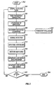
- FIG. 2 is a flow diagram of the a preferred method embodiment of the invention.
- the method shown in FIG. 2 is used for enhancing an incoming acoustic signal, which consists of a plurality of data samples generated as output from the analog-to-digital converter 14 shown in FIG. 1.
- the method begins at a Start state (Step 202).
- the incoming data stream e.g., a previously generated acoustic data file or a digitized live acoustic signal
- Step 204 the invention normally would be applied to enhance a "moving window" of data representing portions of a continuous acoustic data stream, such that the entire data stream is processed.
- an acoustic data stream to be enhanced is represented as a series of data "buffers" of fixed length, regardless of the duration of the original acoustic data stream.
- the samples of a current window are subjected to a time-frequency transformation, which may include appropriate conditioning operations, such as pre-filtering, shading, etc .
- a time-frequency transformation which may include appropriate conditioning operations, such as pre-filtering, shading, etc .
- Any of several time-frequency transformations can be used, such as the short-time Fourier transform, bank of filter analysis, discrete wavelet transform, etc .
- the result of the time-frequency transformation is that the initial time series x ( t ) is transformed into a time-frequency representation X ( f , i ), where t is the sampling index to the time series x, and f and i are discrete variables respectively indexing the frequency and time dimensions of spectrogram X .
- the power level P(f,i) as a function of time and frequency will be referred to as the "spectrogram" from now on.
- the power levels in individual bands f are then subjected to background noise estimation (Step 208) coupled with transient isolation (Step 210).
- Transient isolation detects the presence of transient signals buried in stationary noise and outputs estimated starting and ending times for such transients. Transients can be instances of the sought signal, but can also be impulsive noise.
- the background noise estimation updates the estimate of the background noise parameters between transients.
- a preferred embodiment for performing background noise estimation comprises a power detector that averages the acoustic power in a sliding window for each frequency band f .
- the power detector declares the presence of a signal, i . e ., when: P ( f , i ) > B ( f ) + c ⁇ ( f ) , where B ( f ) is the mean background noise power in band f, ⁇ ( f ) is the standard deviation of the noise in that same band, and c is a constant.
- noise estimation need not be dynamic, but could be measured once (for example, during boot-up of a computer running software implementing the invention).
- the transformed data that is passed through the transient detector is then applied to a signal detector function (Step 212).
- This step allows the system to discriminate against transient noises that are not of the same class as the signal.
- a voice detector is applied at this step.
- the autocorrelation of b ( i ) is calculated as a function of the time lag ⁇ , for ⁇ maxpitch ⁇ ⁇ ⁇ ⁇ minpitch , where ⁇ maxpitch is the lag corresponding to the maximum voice pitch allowed, while ⁇ minpitch is the lag corresponding to the minimum voice pitch allowed.
- the statistic on which the voice/unvoiced decision is based is the value of the normalized autocorrelation (autocorrelation coefficient) of b ( i ), calculated in a window centered at time period i . If the maximum normalized autocorrelation is greater than a threshold, it is deemed to contain voice.
- This method exploits the pulsing nature of the human voice, characterized by glottal pulses appearing in the short-time spectrogram. Those glottal pulses line up along the frequency dimension of the spectrogram. If the voice dominates at least some region of the frequency domain, then the autocorrelation of the sum will exhibit a maximum at the value of the pitch period corresponding to the voice.
- the advantage of this voice detection method is that it is robust to noise interference over large portions of the spectrum, since it is only necessary to have good SNR over portion of the spectrum for the autocorrelation coefficient of b(i) to be high.
- the spectrograms P from Steps 208 and 210 are preferably then rescaled so that they can be compared to stored templates (Step 214).
- rescaling is to align preferentially the frequency bands of the templates having a higher SNR.
- rescaling is optional and need not be used in all embodiments.
- the SNR of the templates is used as well as the SNR of the measured spectra for the rescaling of the templates.
- the preferred embodiment After spectral rescaling, the preferred embodiment performs pattern matching to find a template T * in the signal model that best matches the current spectrogram P ( f , i ) (Step 216). There exists some latitude in the definition of the term "best match", as well as in the method used to find that best match.
- the template with the smallest r.m.s. (root mean square) difference d * between P + k and T* is found.
- the frequency bands with the least SNR contribute less to the distance calculation than those bands with more SNR.
- a low-noise spectrogram C is generated by merging the selected closest template T * with the measured spectrogram P (Step 218).
- a low-noise spectrogram C is reconstructed from P and T *.
- a low-noise output time series y is synthesized (Step 220).
- the harmonic part is synthesized using a series of harmonics c ( t , j ). An arbitrary initial phase ⁇ 0 ( j ) is selected for each component j.
- c ( t , j ) A ( t , j ) sin [ f 0 j t + ⁇ 0 ( j ) ] , where A(t, j) is the amplitude of each harmonic j at time t .
- One embodiment uses spline interpolation to generate continuous values of f 0 and A ( t, j) that vary smoothly between spectrogram points.
- the fundamental frequency does not need to track the signal's fundamental frequency.
- a continuous-amplitude and phase reconstruction is performed as for the harmonic part, except that f 0 is held constant.
- a noise generator is used, one for each frequency band of the signal, and the amplitude is made to track that of the low-noise spectrogram.
- Step 222 If any of the input data remains to be processed (Step 222), then the entire process is repeated on a next sample of acoustic data (Step 204). Otherwise, processing ends (Step 224).
- the final output is a low-noise signal that represents an enhancement of the quality of the original input acoustic signal.
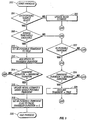
- FIG. 3 is a flow diagram providing a more detailed description of the process of background noise estimation and transient detection which were briefly described as Steps 212 and 208, respectively, in FIG. 2.
- the transient isolation process detects the presence of transient signal buried in stationary noise.
- the background noise estimator updates the estimates of the background noise parameters between transients.
- the process begins at a Start Process state (Step 302).
- the process needs a sufficient number of samples of background noise before it can use the mean and standard deviation of the noise to detect transients. Accordingly, the routine determines if a sufficient number of samples of background noise have been obtained (Step 304). If not, the present sample is used to update the noise estimate (Step 306)and the process is terminated (Step 320).
- the background noise update process the spectrogram elements P ( f , i) are kept in a ring buffer and used to update the mean B ( f ) and the standard deviation ⁇ ( f ) of the noise in each frequency band f .
- the background noise estimate is considered ready when the index i is greater than a preset threshold.
- Step 304 a determination is made as to whether the signal level P ( f, i ) is significantly above the background in some of the frequency bands (Step 308).
- the determination step indicates that the power threshold has been exceeded, i . e ., when P ( f , i ) > B ( f ) + c ⁇ ( f ) , where c is a constant predetermined empirically. Processing then continues at Step 310.
- Step 310 In order to determine if the spectrogram P ( f , i) contains a transient signal, a flag "In-possible-transient" is set to True (Step 310), and the duration of the possible transient is incremented (Step 312). A determination is made as to whether the possible transient is too long to be a transient or not (Step 314). If the possible transient duration is still within the maximum duration, then the process is terminated (Step 320). On the other hand, if the transient duration is judged too long to be a spoken utterance, then it is deemed to be an increase in background noise level. Hence, the noise estimate is updated retroactively (Step 316), the "In-possible-transient" flag is set to False and the transient-duration is reset to 0 (Step 318), and processing terminates (Step 320).
- Step 306. If a sufficiently powerful signal is not detected in Step 308, then the background noise statistics are updated as in Step 306. After that, the "In-possible-transient" flag is tested (Step 322). If the flag it is set to False, then the process ends (Step 320). If the flag is set to True, then it is reset to False and the transient-duration is reset to 0, as in Step 318. The transient is then tested for duration (Step 324). If the transient is deemed too short to be part of a speech utterance, the process ends (Step 320). If the transient is long enough to be a possible speech utterance, then the transient flag is set to True, and the beginning and end of the transient are passed up to the calling routine (Step 326). The process then ends (Step 320).
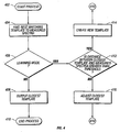
- FIG. 4 is a flow diagram providing a more detailed description of the process of pattern matching which was briefly described as Step 216 of FIG. 2.
- the process begins at a Start Process state (Step 402).
- the pattern matching process finds a template T * in the signal model that best matches the considered spectrogram P ( f , i ) (Step 404).
- the pattern matching process is also responsible for the learning process of the signal model. There exists some latitude in the definition of the term "best match", as well as in the method used to find that best match.
- the template with the smallest r.m.s. difference d * between P + k and T * is found.
- the r.m.s. distance is calculated by:
- the frequency bands with the least SNR contribute less to the distance calculation than those bands with more SNR.
- Step 406 the template T* ( f, i) most similar to P(f, i) is used to adjust the signal model.
- the manner in which T *( f , i) is incorporated in the model depends on the value of d* ( i ) (Step 412). If d* ( i ) ⁇ d max , where d max is a predetermined threshold, then T* ( f, i) is adjusted (Step 416), and the process ends (Step 410).
- the preferred embodiment of Step 416 is implemented such that T* ( f, i ) is the average of all spectra P ( f, i ) that are used to compose T* ( f, i ).
- the invention may be implemented in hardware or software, or a combination of both (e.g., programmable logic arrays). Unless otherwise specified, the algorithms included as part of the invention are not inherently related to any particular computer or other apparatus. In particular, various general purpose machines may be used with programs written in accordance with the teachings herein, or it may be more convenient to construct more specialized apparatus to perform the required method steps. However, preferably, the invention is implemented in one or more computer programs executing on programmable systems each comprising at least one processor, at least one data storage system (including volatile and non-volatile memory and/or storage elements), at least one input device, and at least one output device. Each such programmable system component constitutes a means for performing a function. The program code is executed on the processors to perform the functions described herein.
- Each such program may be implemented in any desired computer language (including machine, assembly, high level procedural, or object oriented programming languages) to communicate with a computer system.
- the language may be a compiled or interpreted language.
- Each such computer program is preferably stored on a storage media or device (e . g ., ROM, CD-ROM, or magnetic or optical media) readable by a general or special purpose programmable computer, for configuring and operating the computer when the storage media or device is read by the computer to perform the procedures described herein.
- a storage media or device e . g ., ROM, CD-ROM, or magnetic or optical media
- the inventive system may also be considered to be implemented as a computer-readable storage medium, configured with a computer program, where the storage medium so configured causes a computer to operate in a specific and predefined manner to perform the functions described herein.
Landscapes
- Engineering & Computer Science (AREA)
- Computational Linguistics (AREA)
- Quality & Reliability (AREA)
- Signal Processing (AREA)
- Health & Medical Sciences (AREA)
- Audiology, Speech & Language Pathology (AREA)
- Human Computer Interaction (AREA)
- Physics & Mathematics (AREA)
- Acoustics & Sound (AREA)
- Multimedia (AREA)
- Circuit For Audible Band Transducer (AREA)
- Measurement Of Mechanical Vibrations Or Ultrasonic Waves (AREA)
- Devices For Supply Of Signal Current (AREA)
- Amplifiers (AREA)
- Noise Elimination (AREA)
- Measurement Of Velocity Or Position Using Acoustic Or Ultrasonic Waves (AREA)
Abstract
Description
- This invention relates to systems and methods for enhancing the quality of an acoustic signal degraded by additive noise.
- There are several fields of research studying acoustic signal enhancement, with the emphasis being on speech signals. Among those are: voice communication, automatic speech recognition (ASR), and hearing aids. Each field of research has adopted its own approaches to acoustic signal enhancement, with some overlap between them.
- Acoustic signals are often degraded by the presence of noise. For example, in a busy office or a moving automobile, the performance of ASR systems degrades substantially. If voice is transmitted to a remote listener - as in a teleconferencing system - the presence of noise can be annoying or distracting to the listener, or even make the speech difficult to understand. People with a loss of hearing have notable difficulty understanding speech in noisy environment, and the overall gain applied to the signal by most current hearing aids does not help alleviate the problem. Old music recordings are often degraded by the presence of impulsive noise or hissing. Other examples of communication where acoustic signal degradation by noise occurs include telephony, radio communications, video-conferencing, computer recordings, etc.
- Continuous speech large vocabulary ASR is particularly sensitive to noise interference, and the solution adopted by the industry so far has been the use of headset microphones. Noise reduction is obtained by the proximity of the microphone to the mouth of the subject (about one-half inch), and sometimes also by special proximity effect microphones. However, a user often finds it awkward to be tethered to a computer by the headset, and annoying to be wearing an obtrusive piece of equipment. The need to use a headset precludes impromptu human-machine interactions, and is a significant barrier to market penetration of ASR technology.
- Apart from close-proximity microphones, traditional approaches to acoustic signal enhancement in communication have been adaptive filtering and spectral subtraction. In adaptive filtering, a second microphone samples the noise but not the signal. The noise is then subtracted from the signal. One problem with this approach is the cost of the second microphone, which needs to be placed at a different location from the one used to pick up the source of interest. Moreover, it is seldom possible to sample only the noise and not include the desired source signal. Another form of adaptive filtering applies bandpass digital filtering to the signal. The parameters of the filter are adapted so as to maximize the signal-to-noise ratio (SNR), with the noise spectrum averaged over long periods of time. This method has the disadvantage of leaving out the signal in the bands with low SNR.
- In spectral subtraction, the spectrum of the noise is estimated during periods where the signal is absent, and then subtracted from the signal spectrum when the signal is present. However, this leads to the introduction of "musical noise" and other distortions that are unnatural. The origin of those problems is that, in regions of very low SNR, all that spectral subtraction can determine is that the signal is below a certain level. By being forced to make a choice of signal level based on sometimes poor evidence, a considerable departure from the true signal often occurs in the form of noise and distortion.
- A recent approach to noise reduction has been the use of beamforming using an array of microphones. This technique requires specialized hardware, such as multiple microphones, A/D converters, etc., thus raising the cost of the system. Since the computational cost increases proportionally to the square of the number of microphones, that cost also can become prohibitive. Another limitation of microphone arrays is that some noise still leaks through the beamforming process. Moreover, actual array gains are usually much lower than those measured in anechoic conditions, or predicted from theory, because echoes and reverberation of interfering sound sources are still accepted through the mainlobe and sidelobes of the array.
- A noise reduction system based on template matching is known from T F Quatieri et al, "Noise reduction using a soft decision sine-wave vector quantizer", ICASSP'90, pages 821-824, 03-04-1990.
- The inventor has determined that it would be desirable to be able to enhance an acoustic signal without leaving out any part of the spectrum, introducing unnatural noise, or distorting the signal, and without the expense of microphone arrays. The present invention provides a system and method for acoustic signal enhancement that avoids the limitations of prior techniques.
- The invention, ω defined by the appended independent claims, includes a method, apparatus, and computer program to enhance the quality of an acoustic signal by processing an input signal in such a manner as to produce a corresponding output that has very low levels of noise ("signal" is used to mean a signal of interest; background and distracting sounds against which the signal is to be enhanced is referred to as "noise"). In the preferred embodiment, enhancement is accomplished by the use of a signal model augmented by learning. The input signal may represent human speech, but it should be recognized that the invention could be used to enhance any type of live or recorded acoustic data, such as musical instruments and bird or human singing.
- The preferred embodiment of the invention enhances input signals as follows: An input signal is digitized into binary data which is transformed to a time-frequency representation. Background noise is estimated and transient sounds are isolated. A signal detector is applied to the transients. Long transients without signal content and the background noise between the transients are included in the noise estimate. If at least some part of a transient contains signal of interest, the spectrum of the signal is compared to the signal model after rescaling, and the signal's parameters are fitted to the data. Low-noise signal is resynthesized using the best fitting set of signal model parameters. Since the signal model only incorporates low noise signal, the output signal also has low noise. The signal model is trained with low-noise signal data by creating templates from the spectrograms when they are significantly different from existing templates. If an existing template is found that resembles the input pattern, the template is averaged with the pattern in such a way that the resulting template is the average of all the spectra that matched that template in the past. The knowledge of signal characteristics thus incorporated in the model serves to constrict the reconstruction of the signal, thereby avoiding introduction of unnatural noise or distortions.
- The invention has the following advantages: it can output resynthesized signal data that is devoid of both impulsive and stationary noise, it needs only a single microphone as a source of input signals, and the output signal in regions of low SNR is kept consistent with those spectra the source could generate.
- The details of one or more embodiments of the invention are set forth in the accompanying drawings and the description below. Other features, objects, and advantages of the invention will be apparent from the description and drawings, and from the claims.
-
- FIG. 1 is block diagram of a prior art programmable computer system suitable for implementing the signal enhancement technique of the invention.
- FIG. 2 is a flow diagram showing the basic method of the preferred embodiment of the invention.
- FIG. 3 is a flow diagram showing a preferred process for detecting and isolating transients in input data and estimating background noise parameters.
- FIG. 4 is a flow diagram showing a preferred method for generating and using the signal model templates.
- Like reference numbers and designations in the various drawings indicate like elements.
- Throughout this description, the preferred embodiment and examples shown should be considered as exemplars rather than as limitations of the invention.
- FIG. 1 shows a block diagram of a typical prior art programmable processing system which may be used for implementing the signal enhancement system of the invention. An acoustic signal is received at a
transducer microphone 10, which generates a corresponding electrical signal representation of the acoustic signal. The signal from thetransducer microphone 10 is then preferably amplified by anamplifier 12 before being digitized by an analog-to-digital converter 14. The output of the analog-to-digital converter 14 is applied to a processing system which applies the enhancement techniques of the invention. The processing system preferably includes aCPU 16,RAM 20, ROM 18 (which may be writable, such as a flash ROM), and anoptional storage device 22, such as a magnetic disk, coupled by aCPU bus 23 as shown. The output of the enhancement process can be applied to other processing systems, such as an ASR system, or saved to a file, or played back for the benefit of a human listener. Playback is typically accomplished by converting the processed digital output stream into an analog signal by means of a digital-to-analog converter 24, and amplifying the analog signal with anoutput amplifier 26 which drives an audio speaker 28 (e.g., a loudspeaker, headphone, or earphone). - The following describes the functional components of an acoustic signal enhancement system. A first functional component of the invention is a dynamic background noise estimator that transforms input data to a time-frequency representation. The noise estimator provides a means of estimating continuous or slowly-varying background noise causing signal degradation. The noise estimator should also be able to adapt to a sudden change in noise levels, such as when a source of noise is activated (e.g., an air-conditioning system coming on or off). The dynamic background noise estimation function is capable of separating transient sounds from background noise, and estimate the background noise alone. In one embodiment, a power detector acts in each of multiple frequency bands. Noise-only portions of the data are used to generate mean and standard-deviation of the noise in decibels (dB). When the power exceeds the mean by more than a specified number of standard deviations in a frequency band, the corresponding time period is flagged as containing signal and is not used to estimate the noise-only spectrum.
- The dynamic background noise estimator works closely with a second functional component, a transient detector. A transient occurs when acoustic power rises and then falls again within a relatively short period of time. Transients can be speech utterances, but can also be transient noises, such as banging, door slamming, etc. Isolation of transients allow them to be studied separately and classified into signal and non-signal events. Also, it is useful to recognize when a rise in power level is permanent, such as when a new source of noise is turned on. This allows the system to adapt to that new noise level.
- The third functional component of the invention is a signal detector. A signal detector is useful to discriminate non-signal non-stationary noise. In the case of harmonic sounds, it is also used to provide a pitch estimate if it is desired that a human listener listens to the reconstructed signal. A preferred embodiment of a signal detector that detects voice in the presence of noise is described below. The voice detector uses glottal pulse detection in the frequency domain. A spectrogram of the data is produced (temporal-frequency representation of the signal) and, after taking the logarithm of the spectrum, the signal is summed along the time axis up to a frequency threshold. A high autocorrelation of the resulting time series is indicative of voiced speech. The pitch of the voice is the lag for which the autocorrelation is maximum.
- The fourth functional component is a spectral rescaler. The input signal can be weak or strong, close or far. Before measured spectra are matched against templates in a model, the measured spectra is rescaled so that the inter-pattern distance does not depend on the overall loudness of the signal. In the preferred embodiment, weighting is proportional to the SNR in decibels (dB). The weights are bounded below and above by a minimum and a maximum value, respectively. The spectra are rescaled so that the weighted distance to each stored template is minimum.
- The fifth functional component is a pattern matcher. The distance between templates and the measured spectrogram can be one of several appropriate metrics, such as the Euclidian distance or a weighted Euclidian distance. The template with the smallest distance to the measured spectrogram is selected as the best fitting prototype. The signal model consists of a set of prototypical spectrograms of short duration obtained from low-noise signal. Signal model training is accomplished by collecting spectrograms that are significantly different from prototypes previously collected. The first prototype is the first signal spectrogram containing signal significantly above the noise. For subsequent time epochs, if the spectrogram is closer to any existing prototype than a selected distance threshold, then the spectrogram is averaged with the closest prototype. If the spectrogram is farther away from any prototype than the selected threshold, then the spectrogram is declared to be a new prototype.
- The sixth functional component is a low-noise spectrogram generator. A low-noise spectrogram is generated from a noisy spectrogram generated by the pattern matcher by replacing data in the low SNR spectrogram bins with the value of the best fitting prototype. In the high SNR spectrogram bins, the measured spectra are left unchanged. A blend of prototype and measured signal is used in the intermediate SNR. cases.
- The seventh functional component is a resynthesizer. An output signal is resynthesized from the low-noise spectrogram. A preferred embodiment proceeds as follows. The signal is divided into harmonic and non-harmonic parts. For the harmonic part, an arbitrary initial phase is selected for each component. Then, for each point of non-zero output, the amplitude of each component is interpolated from the spectrogram, and the fundamental frequency is interpolated from the output of the signal detector. Each component is synthesized separately, each with a continuous phase, amplitude, and an harmonic relationship between their frequencies. The output of the harmonic part is the sum of the components.
- For the non-harmonic part of the signal, the fundamental frequency of the resynthesized time series does not need to track the signal's fundamental frequency. In one embodiment, a continuous-amplitude and phase reconstruction is performed as for the harmonic part, except that the fundamental frequency is held constant. In another embodiment, noise generators are used, one for each frequency band of the signal, and the amplitude is tracking that of the low-noise spectrogram through interpolation. In yet another embodiment, constant amplitude windows of band-passed noise are added after their overall amplitude is adjusted to that of the spectrogram at that point.
- FIG. 2 is a flow diagram of the a preferred method embodiment of the invention. The method shown in FIG. 2 is used for enhancing an incoming acoustic signal, which consists of a plurality of data samples generated as output from the analog-to-
digital converter 14 shown in FIG. 1. The method begins at a Start state (Step 202). The incoming data stream (e.g., a previously generated acoustic data file or a digitized live acoustic signal) is read into a computer memory as a set of samples (Step 204). In the preferred embodiment, the invention normally would be applied to enhance a "moving window" of data representing portions of a continuous acoustic data stream, such that the entire data stream is processed. Generally, an acoustic data stream to be enhanced is represented as a series of data "buffers" of fixed length, regardless of the duration of the original acoustic data stream. - The samples of a current window are subjected to a time-frequency transformation, which may include appropriate conditioning operations, such as pre-filtering, shading, etc. (Step 206). Any of several time-frequency transformations can be used, such as the short-time Fourier transform, bank of filter analysis, discrete wavelet transform, etc.
- The result of the time-frequency transformation is that the initial time series x(t) is transformed into a time-frequency representation X(f, i), where t is the sampling index to the time series x, and f and i are discrete variables respectively indexing the frequency and time dimensions of spectrogram X. In the preferred embodiment, the logarithm of the magnitude of X is used instead of X (Step 207) in subsequent steps unless specified otherwise, i.e.:

- The power level P(f,i) as a function of time and frequency will be referred to as the "spectrogram" from now on.
- The power levels in individual bands f are then subjected to background noise estimation (Step 208) coupled with transient isolation (Step 210). Transient isolation detects the presence of transient signals buried in stationary noise and outputs estimated starting and ending times for such transients. Transients can be instances of the sought signal, but can also be impulsive noise. The background noise estimation updates the estimate of the background noise parameters between transients.
- A preferred embodiment for performing background noise estimation comprises a power detector that averages the acoustic power in a sliding window for each frequency band f. When the power within a predetermined number of frequency bands exceeds a threshold determined as a certain number of standard deviation above the background noise, the power detector declares the presence of a signal, i.e., when:

where B(f) is the mean background noise power in band f, σ(f) is the standard deviation of the noise in that same band, and c is a constant. In an alternative embodiment, noise estimation need not be dynamic, but could be measured once (for example, during boot-up of a computer running software implementing the invention). - The transformed data that is passed through the transient detector is then applied to a signal detector function (Step 212). This step allows the system to discriminate against transient noises that are not of the same class as the signal. For speech enhancement, a voice detector is applied at this step. In particular, in the preferred voice detector, the level P(f, i) is summed along the time axis

- Next, the autocorrelation of b(i) is calculated as a function of the time lag τ, for τmaxpitch ≺τ≺ τminpitch, where τmaxpitch is the lag corresponding to the maximum voice pitch allowed, while τminpitch is the lag corresponding to the minimum voice pitch allowed. The statistic on which the voice/unvoiced decision is based is the value of the normalized autocorrelation (autocorrelation coefficient) of b(i), calculated in a window centered at time period i. If the maximum normalized autocorrelation is greater than a threshold, it is deemed to contain voice. This method exploits the pulsing nature of the human voice, characterized by glottal pulses appearing in the short-time spectrogram. Those glottal pulses line up along the frequency dimension of the spectrogram. If the voice dominates at least some region of the frequency domain, then the autocorrelation of the sum will exhibit a maximum at the value of the pitch period corresponding to the voice. The advantage of this voice detection method is that it is robust to noise interference over large portions of the spectrum, since it is only necessary to have good SNR over portion of the spectrum for the autocorrelation coefficient of b(i) to be high.
- Another embodiment of the voice detector weights the spectrogram elements before summing them in order to decrease the contribution of the

- The weights w(i) are proportional to the SNR r(f, i) in band f at time i, calculated as a difference of levels, i.e. r(f,i) = P(f, i) - B(f) for each frequency band. In this embodiment, each element of the rescaling factor is weighted by a weight defined as follows, where w min and w max are preset thresholds:


- In the preferred embodiment, the weights are normalized by the sum of the weights at each time frame, i.e.:


- The spectrograms P from
Steps 
- In another embodiment, weighting is used in the rescaling of the templates prior to comparison:

- The effect of such rescaling is to align preferentially the frequency bands of the templates having a higher SNR. However, rescaling is optional and need not be used in all embodiments.
- In another embodiment, the SNR of the templates is used as well as the SNR of the measured spectra for the rescaling of the templates. The SNR of template T(f, m) is defined as r N(f, m) = T(f, m)-B N(f), where B N(f) is the background noise in frequency band f at the time of training. In one embodiment of a weighting scheme using both r and r N, the weights w N are


- Other combinations of r N and r are admissible. In the preferred embodiment, the weights are normalized by the sum of the weights at each time fiame, i.e.:


- After spectral rescaling, the preferred embodiment performs pattern matching to find a template T* in the signal model that best matches the current spectrogram P(f, i) (Step 216). There exists some latitude in the definition of the term "best match", as well as in the method used to find that best match. In one embodiment, the template with the smallest r.m.s. (root mean square) difference d* between P + k and T* is found. In the preferred embodiment, the weighted r.m.s. distance is used, where:

- In this embodiment, the frequency bands with the least SNR contribute less to the distance calculation than those bands with more SNR. The best matching template T*(i) at time i is selected by finding m such that d*(i) = min m (d(i,m)).
- Next, a low-noise spectrogram C is generated by merging the selected closest template T* with the measured spectrogram P (Step 218). For each window position i, a low-noise spectrogram C is reconstructed from P and T*. In the preferred embodiment, the reconstruction takes place the following way. For each time-frequency bin:

- After generating a low-noise spectrogram C, a low-noise output time series y is synthesized (Step 220). In the preferred embodiment, the spectrogram is divided into harmonic (y h ) and non-harmonic (y u ) parts and each part is reconstructed separately (i.e., y = y h + y u ). The harmonic part is synthesized using a series of harmonics c(t,j). An arbitrary initial phase φ0(j) is selected for each component j. Then for each output point y h (t) the amplitude of each component is interpolated from the spectrogram C, and the fundamental frequency f 0 is interpolated from the output of the voice detector. The components c(t, j) are synthesized separately, each with a continuous phase, amplitude, and a common pitch relationship with the other components:

where A(t, j) is the amplitude of each harmonic j at time t. One embodiment uses spline interpolation to generate continuous values of f 0 and A(t, j) that vary smoothly between spectrogram points. - The harmonic part of the output is the sum of the components, y h (t)= sum j [c(t,j)]. For the non-harmonic part of the signal y u , the fundamental frequency does not need to track the signal's fundamental frequency. In one embodiment, a continuous-amplitude and phase reconstruction is performed as for the harmonic part, except that f 0 is held constant. In another embodiment, a noise generator is used, one for each frequency band of the signal, and the amplitude is made to track that of the low-noise spectrogram.
- If any of the input data remains to be processed (Step 222), then the entire process is repeated on a next sample of acoustic data (Step 204). Otherwise, processing ends (Step 224). The final output is a low-noise signal that represents an enhancement of the quality of the original input acoustic signal.
- FIG. 3 is a flow diagram providing a more detailed description of the process of background noise estimation and transient detection which were briefly described as
Steps - The process begins at a Start Process state (Step 302). The process needs a sufficient number of samples of background noise before it can use the mean and standard deviation of the noise to detect transients. Accordingly, the routine determines if a sufficient number of samples of background noise have been obtained (Step 304). If not, the present sample is used to update the noise estimate (Step 306)and the process is terminated (Step 320). In one embodiment of the background noise update process, the spectrogram elements P(f, i) are kept in a ring buffer and used to update the mean B(f) and the standard deviation σ(f) of the noise in each frequency band f. The background noise estimate is considered ready when the index i is greater than a preset threshold.
- If the background samples are ready (Step 304), then a determination is made as to whether the signal level P(f, i) is significantly above the background in some of the frequency bands (Step 308). In a preferred embodiment, when the power within a predetermined number of frequency bands is greater than a threshold determined as a certain number of standard deviations above the background noise mean level, the determination step indicates that the power threshold has been exceeded, i.e., when

where c is a constant predetermined empirically. Processing then continues atStep 310. - In order to determine if the spectrogram P(f, i) contains a transient signal, a flag "In-possible-transient" is set to True (Step 310), and the duration of the possible transient is incremented (Step 312). A determination is made as to whether the possible transient is too long to be a transient or not (Step 314). If the possible transient duration is still within the maximum duration, then the process is terminated (Step 320). On the other hand, if the transient duration is judged too long to be a spoken utterance, then it is deemed to be an increase in background noise level. Hence, the noise estimate is updated retroactively (Step 316), the "In-possible-transient" flag is set to False and the transient-duration is reset to 0 (Step 318), and processing terminates (Step 320).
- If a sufficiently powerful signal is not detected in
Step 308, then the background noise statistics are updated as inStep 306. After that, the "In-possible-transient" flag is tested (Step 322). If the flag it is set to False, then the process ends (Step 320). If the flag is set to True, then it is reset to False and the transient-duration is reset to 0, as inStep 318. The transient is then tested for duration (Step 324). If the transient is deemed too short to be part of a speech utterance, the process ends (Step 320). If the transient is long enough to be a possible speech utterance, then the transient flag is set to True, and the beginning and end of the transient are passed up to the calling routine (Step 326). The process then ends (Step 320). - FIG. 4 is a flow diagram providing a more detailed description of the process of pattern matching which was briefly described as
Step 216 of FIG. 2. The process begins at a Start Process state (Step 402). The pattern matching process finds a template T* in the signal model that best matches the considered spectrogram P(f, i) (Step 404). The pattern matching process is also responsible for the learning process of the signal model. There exists some latitude in the definition of the term "best match", as well as in the method used to find that best match. In one embodiment, the template with the smallest r.m.s. difference d* between P + k and T* is found. In the preferred embodiment, the weighted r.m.s. distance is used to measure the degree of
- In this embodiment, the frequency bands with the least SNR contribute less to the distance calculation than those bands with more SNR. The best matching template T*(f, i) that is the output of
Step 404 at time i is selected by finding m such that d*(i) = min m [d(i, m)]. If the system is not in learning mode (Step 406), then T*(f, i) is also the output of the process as being the closest template (Step 408). The process then ends (Step 410) - If the system is in learning mode (Step 406), the template T*(f, i) most similar to P(f, i) is used to adjust the signal model. The manner in which T*(f, i) is incorporated in the model depends on the value of d*(i) (Step 412). If d*(i) < d max , where d max is a predetermined threshold, then T*(f, i) is adjusted (Step 416), and the process ends (Step 410). The preferred embodiment of
Step 416 is implemented such that T*(f, i) is the average of all spectra P(f, i) that are used to compose T*(f, i). In the preferred embodiment, the number n m of spectra associated with T(f, m) is kept in memory, and when a new spectrum P(f, i) is used to adjust T(f, m), the adjusted template is:

- Going back to
Step 412, if d*(i) > d max , then a new template is created (Step 414), T*(f, i) = P(f, i), with a weight n m = 1, and the process ends (Step 410). - The invention may be implemented in hardware or software, or a combination of both (e.g., programmable logic arrays). Unless otherwise specified, the algorithms included as part of the invention are not inherently related to any particular computer or other apparatus. In particular, various general purpose machines may be used with programs written in accordance with the teachings herein, or it may be more convenient to construct more specialized apparatus to perform the required method steps. However, preferably, the invention is implemented in one or more computer programs executing on programmable systems each comprising at least one processor, at least one data storage system (including volatile and non-volatile memory and/or storage elements), at least one input device, and at least one output device. Each such programmable system component constitutes a means for performing a function. The program code is executed on the processors to perform the functions described herein.
- Each such program may be implemented in any desired computer language (including machine, assembly, high level procedural, or object oriented programming languages) to communicate with a computer system. In any case, the language may be a compiled or interpreted language.
- Each such computer program is preferably stored on a storage media or device (e.g., ROM, CD-ROM, or magnetic or optical media) readable by a general or special purpose programmable computer, for configuring and operating the computer when the storage media or device is read by the computer to perform the procedures described herein. The inventive system may also be considered to be implemented as a computer-readable storage medium, configured with a computer program, where the storage medium so configured causes a computer to operate in a specific and predefined manner to perform the functions described herein.
- A number of embodiments of the invention have been described. Nevertheless, it will be understood that various modifications- may be made without departing from the scope of the invention. For example, some of the steps of various of the algorithms may be order independent, and thus may be executed in an order other than as described above. Accordingly, other embodiments are within the scope of the following claims.
Claims (6)
- A method for enhancing acoustic signal buried in noise within a digitized acoustic input signal, including:(a) transforming the digitized acoustic input signal to a time-frequency representation (206);(b) estimating a background noise level in the time-frequency representation (208);(c) for each interval of the time-frequency representation containing significant signal levels, comparing the time-frequency representation of such interval with a signal model and determining a template in the signal model that best matches the time-frequency representation of such interval, based in part on signal to noise ratio (216); and(d) replacing the digitized acoustic input signal with a low-noise output signal comprising a mix of the digitized acoustic input signal and the best matching template (218, 220).
- A method for enhancing acoustic signal buried in noise within a digitized acoustic input signal, including:(a) transforming the digitized acoustic input signal to a time-frequency representation (206);(b) isolating transient sounds within the time-frequency representation (210);(c) estimating background noise and including long transients without signal content and background noise between transients in such estimating (208);(d) rescaling the time-frequency representation of (214) the transient sounds;(e) comparing the rescaled time-frequency representation of each transient containing any signal of interest with a signal model and determining a template in the signal model that best matches such representation (216); and(f) resynthesizing a low-noise output signal using the best matching template (218, 220).
- A system for enhancing acoustic signal buried in noise within a digitized acoustic input signal, including:(a) means for transforming the digitized acoustic input signal to a time-frequency representation (206);(b) means for estimating a background noise level in the time-frequency representation (208);(c) for each interval of the time-frequency representation containing significant signal levels, means for comparing the time-frequency representation of such interval with a signal model and determining a template in the signal model that best matches the time-frequency representation of such interval, based in part on signal to noise ratio (216); and(d) means for replacing the digitized acoustic input signal with a low-noise output signal comprising a mix of the digitized acoustic input signal and the best matching template (218, 220).
- A system for enhancing acoustic signal buried in noise within a digitized acoustic input signal, including:(a) means for transforming the digitized acoustic input signal to a time-frequency representation (206);(b) means for isolating transient sounds within the time-frequency representation (210);(c) means for estimating background noise and including long transients without signal content and background noise between transients in such estimating (208).(d) means for rescaling the time-frequency representation of (214) the transient sounds;(e) means for comparing the rescaled time-frequency representation of each transient containing any signal of interest with a signal model and determining a template in the signal model that best matches such representation (216); and(f) means for resynthesizing a low-noise output signal using the best matching template (218, 220).
- A computer program, stored on a computer-readable medium, for enhancing acoustic signal buried in noise within a digitized acoustic input signal, the computer program comprising instructions for causing a computer to:(a) transform the digitized acoustic input signal to a time-frequency representation (206);(b) estimate a background noise level in the time-frequency representation (208);(c) for each interval of the time-frequency representation containing significant signal levels, compare the time-frequency representation of such interval with a signal model and determine a template in the signal model that best matches the time-frequency representation of such interval, based in part on signal to noise ratio (216); and(d) replace the digitized acoustic input signal with a low-noise output signal comprising a mix of the digitized acoustic input signal and the best matching template (218, 220).
- A computer program, stored on a computer-readable medium, for enhancing acoustic signal buried in noise within a digitized acoustic input signal, the computer program comprising instructions for causing a computer to:(a) transform the digitized acoustic input signal to a time-frequency representation (206);(b) isolate transient sounds within the time-frequency representation (210);(c) estimate background noise and include long transients without signal content and background noise between transients in such estimate (208);(d) rescale the time-frequency representation of (214) the transient sounds;(e) compare the rescaled time-frequency representation of each transient containing any signal of interest with a signal model and determine a template in the signal model that best matches such representation (216); and(f) resynthesize a low-noise output signal using the best matching template (218, 220).
Applications Claiming Priority (3)
| Application Number | Priority Date | Filing Date | Title |
|---|---|---|---|
| US09/375,309 US6910011B1 (en) | 1999-08-16 | 1999-08-16 | Noisy acoustic signal enhancement |
| US375309 | 1999-08-16 | ||
| PCT/US2000/022201 WO2001013364A1 (en) | 1999-08-16 | 2000-08-11 | Method for enhancement of acoustic signal in noise |
Publications (2)
| Publication Number | Publication Date |
|---|---|
| EP1208563A1 EP1208563A1 (en) | 2002-05-29 |
| EP1208563B1 true EP1208563B1 (en) | 2006-04-19 |
Family
ID=23480366
Family Applications (1)
| Application Number | Title | Priority Date | Filing Date |
|---|---|---|---|
| EP00955497A Expired - Lifetime EP1208563B1 (en) | 1999-08-16 | 2000-08-11 | Noisy acoustic signal enhancement |
Country Status (8)
| Country | Link |
|---|---|
| US (2) | US6910011B1 (en) |
| EP (1) | EP1208563B1 (en) |
| JP (1) | JP4764995B2 (en) |
| AT (1) | ATE323937T1 (en) |
| AU (1) | AU6769600A (en) |
| CA (1) | CA2382175C (en) |
| DE (1) | DE60027438T2 (en) |
| WO (1) | WO2001013364A1 (en) |
Cited By (1)
| Publication number | Priority date | Publication date | Assignee | Title |
|---|---|---|---|---|
| CN102282867B (en) * | 2009-01-20 | 2014-07-23 | 唯听助听器公司 | Hearing aid and a method of detecting and attenuating transients |
Families Citing this family (76)
| Publication number | Priority date | Publication date | Assignee | Title |
|---|---|---|---|---|
| US6910011B1 (en) * | 1999-08-16 | 2005-06-21 | Haman Becker Automotive Systems - Wavemakers, Inc. | Noisy acoustic signal enhancement |
| US7117149B1 (en) * | 1999-08-30 | 2006-10-03 | Harman Becker Automotive Systems-Wavemakers, Inc. | Sound source classification |
| GB2379114A (en) * | 2001-08-21 | 2003-02-26 | Sony Uk Ltd | Introducing test signals into a data signal |
| US7889879B2 (en) | 2002-05-21 | 2011-02-15 | Cochlear Limited | Programmable auditory prosthesis with trainable automatic adaptation to acoustic conditions |
| US7103541B2 (en) * | 2002-06-27 | 2006-09-05 | Microsoft Corporation | Microphone array signal enhancement using mixture models |
| KR100463657B1 (en) * | 2002-11-30 | 2004-12-29 | 삼성전자주식회사 | Apparatus and method of voice region detection |
| US7895036B2 (en) * | 2003-02-21 | 2011-02-22 | Qnx Software Systems Co. | System for suppressing wind noise |
| US8271279B2 (en) | 2003-02-21 | 2012-09-18 | Qnx Software Systems Limited | Signature noise removal |
| US7725315B2 (en) * | 2003-02-21 | 2010-05-25 | Qnx Software Systems (Wavemakers), Inc. | Minimization of transient noises in a voice signal |
| US7885420B2 (en) * | 2003-02-21 | 2011-02-08 | Qnx Software Systems Co. | Wind noise suppression system |
| US8326621B2 (en) | 2003-02-21 | 2012-12-04 | Qnx Software Systems Limited | Repetitive transient noise removal |
| US7949522B2 (en) * | 2003-02-21 | 2011-05-24 | Qnx Software Systems Co. | System for suppressing rain noise |
| US8073689B2 (en) | 2003-02-21 | 2011-12-06 | Qnx Software Systems Co. | Repetitive transient noise removal |
| GB2398913B (en) * | 2003-02-27 | 2005-08-17 | Motorola Inc | Noise estimation in speech recognition |
| WO2004084179A2 (en) * | 2003-03-15 | 2004-09-30 | Mindspeed Technologies, Inc. | Adaptive correlation window for open-loop pitch |
| US7620546B2 (en) * | 2004-03-23 | 2009-11-17 | Qnx Software Systems (Wavemakers), Inc. | Isolating speech signals utilizing neural networks |
| JP4318119B2 (en) * | 2004-06-18 | 2009-08-19 | 国立大学法人京都大学 | Acoustic signal processing method, acoustic signal processing apparatus, acoustic signal processing system, and computer program |
| US7949520B2 (en) | 2004-10-26 | 2011-05-24 | QNX Software Sytems Co. | Adaptive filter pitch extraction |
| US7680652B2 (en) * | 2004-10-26 | 2010-03-16 | Qnx Software Systems (Wavemakers), Inc. | Periodic signal enhancement system |
| US8306821B2 (en) | 2004-10-26 | 2012-11-06 | Qnx Software Systems Limited | Sub-band periodic signal enhancement system |
| US8543390B2 (en) * | 2004-10-26 | 2013-09-24 | Qnx Software Systems Limited | Multi-channel periodic signal enhancement system |
| US7610196B2 (en) * | 2004-10-26 | 2009-10-27 | Qnx Software Systems (Wavemakers), Inc. | Periodic signal enhancement system |
| US8170879B2 (en) * | 2004-10-26 | 2012-05-01 | Qnx Software Systems Limited | Periodic signal enhancement system |
| US7716046B2 (en) * | 2004-10-26 | 2010-05-11 | Qnx Software Systems (Wavemakers), Inc. | Advanced periodic signal enhancement |
| KR100657912B1 (en) * | 2004-11-18 | 2006-12-14 | 삼성전자주식회사 | Noise reduction method and apparatus |
| US8284947B2 (en) * | 2004-12-01 | 2012-10-09 | Qnx Software Systems Limited | Reverberation estimation and suppression system |
| US7415164B2 (en) * | 2005-01-05 | 2008-08-19 | Mitsubishi Electric Research Laboratories, Inc. | Modeling scenes in videos using spectral similarity |
| US7742914B2 (en) * | 2005-03-07 | 2010-06-22 | Daniel A. Kosek | Audio spectral noise reduction method and apparatus |
| US8027833B2 (en) * | 2005-05-09 | 2011-09-27 | Qnx Software Systems Co. | System for suppressing passing tire hiss |
| US8311819B2 (en) * | 2005-06-15 | 2012-11-13 | Qnx Software Systems Limited | System for detecting speech with background voice estimates and noise estimates |
| US8170875B2 (en) | 2005-06-15 | 2012-05-01 | Qnx Software Systems Limited | Speech end-pointer |
| JP4765461B2 (en) * | 2005-07-27 | 2011-09-07 | 日本電気株式会社 | Noise suppression system, method and program |
| WO2007091956A2 (en) | 2006-02-10 | 2007-08-16 | Telefonaktiebolaget Lm Ericsson (Publ) | A voice detector and a method for suppressing sub-bands in a voice detector |
| US7720681B2 (en) * | 2006-03-23 | 2010-05-18 | Microsoft Corporation | Digital voice profiles |
| US7844453B2 (en) | 2006-05-12 | 2010-11-30 | Qnx Software Systems Co. | Robust noise estimation |
| US9462118B2 (en) * | 2006-05-30 | 2016-10-04 | Microsoft Technology Licensing, Llc | VoIP communication content control |
| US8971217B2 (en) * | 2006-06-30 | 2015-03-03 | Microsoft Technology Licensing, Llc | Transmitting packet-based data items |
| ATE425532T1 (en) * | 2006-10-31 | 2009-03-15 | Harman Becker Automotive Sys | MODEL-BASED IMPROVEMENT OF VOICE SIGNALS |
| US8326620B2 (en) | 2008-04-30 | 2012-12-04 | Qnx Software Systems Limited | Robust downlink speech and noise detector |
| US8335685B2 (en) | 2006-12-22 | 2012-12-18 | Qnx Software Systems Limited | Ambient noise compensation system robust to high excitation noise |
| US20080181392A1 (en) * | 2007-01-31 | 2008-07-31 | Mohammad Reza Zad-Issa | Echo cancellation and noise suppression calibration in telephony devices |
| US8195454B2 (en) * | 2007-02-26 | 2012-06-05 | Dolby Laboratories Licensing Corporation | Speech enhancement in entertainment audio |
| JP5791092B2 (en) * | 2007-03-06 | 2015-10-07 | 日本電気株式会社 | Noise suppression method, apparatus, and program |
| JP5186510B2 (en) * | 2007-03-19 | 2013-04-17 | ドルビー ラボラトリーズ ライセンシング コーポレイション | Speech intelligibility enhancement method and apparatus |
| US20080231557A1 (en) * | 2007-03-20 | 2008-09-25 | Leadis Technology, Inc. | Emission control in aged active matrix oled display using voltage ratio or current ratio |
| US20080274705A1 (en) * | 2007-05-02 | 2008-11-06 | Mohammad Reza Zad-Issa | Automatic tuning of telephony devices |
| US7885810B1 (en) * | 2007-05-10 | 2011-02-08 | Mediatek Inc. | Acoustic signal enhancement method and apparatus |
| EP1995722B1 (en) | 2007-05-21 | 2011-10-12 | Harman Becker Automotive Systems GmbH | Method for processing an acoustic input signal to provide an output signal with reduced noise |
| CN101320559B (en) * | 2007-06-07 | 2011-05-18 | 华为技术有限公司 | Sound activation detection apparatus and method |
| US8605923B2 (en) | 2007-06-20 | 2013-12-10 | Cochlear Limited | Optimizing operational control of a hearing prosthesis |
| US8489396B2 (en) * | 2007-07-25 | 2013-07-16 | Qnx Software Systems Limited | Noise reduction with integrated tonal noise reduction |
| US8904400B2 (en) * | 2007-09-11 | 2014-12-02 | 2236008 Ontario Inc. | Processing system having a partitioning component for resource partitioning |
| US8850154B2 (en) | 2007-09-11 | 2014-09-30 | 2236008 Ontario Inc. | Processing system having memory partitioning |
| JP4970596B2 (en) * | 2007-09-12 | 2012-07-11 | ドルビー ラボラトリーズ ライセンシング コーポレイション | Speech enhancement with adjustment of noise level estimate |
| US8694310B2 (en) | 2007-09-17 | 2014-04-08 | Qnx Software Systems Limited | Remote control server protocol system |
| ATE456130T1 (en) * | 2007-10-29 | 2010-02-15 | Harman Becker Automotive Sys | PARTIAL LANGUAGE RECONSTRUCTION |
| US8209514B2 (en) * | 2008-02-04 | 2012-06-26 | Qnx Software Systems Limited | Media processing system having resource partitioning |
| KR101335417B1 (en) * | 2008-03-31 | 2013-12-05 | (주)트란소노 | Procedure for processing noisy speech signals, and apparatus and program therefor |
| FR2948484B1 (en) * | 2009-07-23 | 2011-07-29 | Parrot | METHOD FOR FILTERING NON-STATIONARY SIDE NOISES FOR A MULTI-MICROPHONE AUDIO DEVICE, IN PARTICULAR A "HANDS-FREE" TELEPHONE DEVICE FOR A MOTOR VEHICLE |
| JP5417099B2 (en) * | 2009-09-14 | 2014-02-12 | 株式会社東京建設コンサルタント | A method for evaluating the state of structures by measuring ultra-low frequency sound |
| US20110134773A1 (en) * | 2009-12-04 | 2011-06-09 | Electronics And Telecommunications Research Institute | Method and apparatus for estimating propagation delay time |
| US8390514B1 (en) * | 2010-01-11 | 2013-03-05 | The Boeing Company | Detection and geolocation of transient signals received by multi-beamforming antenna |
| US8913758B2 (en) * | 2010-10-18 | 2014-12-16 | Avaya Inc. | System and method for spatial noise suppression based on phase information |
| US20120143604A1 (en) * | 2010-12-07 | 2012-06-07 | Rita Singh | Method for Restoring Spectral Components in Denoised Speech Signals |
| US9589580B2 (en) * | 2011-03-14 | 2017-03-07 | Cochlear Limited | Sound processing based on a confidence measure |
| US8990074B2 (en) * | 2011-05-24 | 2015-03-24 | Qualcomm Incorporated | Noise-robust speech coding mode classification |
| US9143107B2 (en) * | 2013-10-08 | 2015-09-22 | 2236008 Ontario Inc. | System and method for dynamically mixing audio signals |
| US9721580B2 (en) * | 2014-03-31 | 2017-08-01 | Google Inc. | Situation dependent transient suppression |
| US9552829B2 (en) * | 2014-05-01 | 2017-01-24 | Bellevue Investments Gmbh & Co. Kgaa | System and method for low-loss removal of stationary and non-stationary short-time interferences |
| CN105261375B (en) * | 2014-07-18 | 2018-08-31 | 中兴通讯股份有限公司 | Activate the method and device of sound detection |
| US9812149B2 (en) * | 2016-01-28 | 2017-11-07 | Knowles Electronics, Llc | Methods and systems for providing consistency in noise reduction during speech and non-speech periods |
| US10249319B1 (en) | 2017-10-26 | 2019-04-02 | The Nielsen Company (Us), Llc | Methods and apparatus to reduce noise from harmonic noise sources |
| CN108470476B (en) * | 2018-05-15 | 2020-06-30 | 黄淮学院 | English pronunciation matching correction system |
| US12046253B2 (en) * | 2021-08-13 | 2024-07-23 | Harman International Industries, Incorporated | Systems and methods for a signal processing device |
| JP7539088B2 (en) | 2021-08-19 | 2024-08-23 | 日本電信電話株式会社 | Feature extraction device, feature extraction method, and program |
| CN117008863B (en) * | 2023-09-28 | 2024-04-16 | 之江实验室 | LOFAR long data processing and displaying method and device |
Family Cites Families (31)
| Publication number | Priority date | Publication date | Assignee | Title |
|---|---|---|---|---|
| US4628156A (en) | 1982-12-27 | 1986-12-09 | International Business Machines Corporation | Canceller trained echo suppressor |
| GB8613327D0 (en) | 1986-06-02 | 1986-07-09 | British Telecomm | Speech processor |
| US4843562A (en) * | 1987-06-24 | 1989-06-27 | Broadcast Data Systems Limited Partnership | Broadcast information classification system and method |
| US5027410A (en) * | 1988-11-10 | 1991-06-25 | Wisconsin Alumni Research Foundation | Adaptive, programmable signal processing and filtering for hearing aids |
| JP2974423B2 (en) * | 1991-02-13 | 1999-11-10 | シャープ株式会社 | Lombard Speech Recognition Method |
| US5680508A (en) * | 1991-05-03 | 1997-10-21 | Itt Corporation | Enhancement of speech coding in background noise for low-rate speech coder |
| JPH0573090A (en) * | 1991-09-18 | 1993-03-26 | Fujitsu Ltd | Speech recognizing method |
| NO941999L (en) | 1993-06-15 | 1994-12-16 | Ontario Hydro | Automated intelligent monitoring system |
| JP3186007B2 (en) * | 1994-03-17 | 2001-07-11 | 日本電信電話株式会社 | Transform coding method, decoding method |
| US5502688A (en) | 1994-11-23 | 1996-03-26 | At&T Corp. | Feedforward neural network system for the detection and characterization of sonar signals with characteristic spectrogram textures |
| JPH10509256A (en) * | 1994-11-25 | 1998-09-08 | ケイ. フインク,フレミング | Audio signal conversion method using pitch controller |
| JP3254953B2 (en) * | 1995-02-17 | 2002-02-12 | 日本ビクター株式会社 | Highly efficient speech coding system |
| US5949888A (en) * | 1995-09-15 | 1999-09-07 | Hughes Electronics Corporaton | Comfort noise generator for echo cancelers |
| JPH1049197A (en) * | 1996-08-06 | 1998-02-20 | Denso Corp | Device and method for voice restoration |
| JPH09212196A (en) * | 1996-01-31 | 1997-08-15 | Nippon Telegr & Teleph Corp <Ntt> | Noise suppressor |
| JP3452443B2 (en) * | 1996-03-25 | 2003-09-29 | 三菱電機株式会社 | Speech recognition device under noise and speech recognition method under noise |
| JPH09258783A (en) * | 1996-03-26 | 1997-10-03 | Mitsubishi Electric Corp | Voice recognizing device |
| US6167375A (en) * | 1997-03-17 | 2000-12-26 | Kabushiki Kaisha Toshiba | Method for encoding and decoding a speech signal including background noise |
| JP3255077B2 (en) * | 1997-04-23 | 2002-02-12 | 日本電気株式会社 | Phone |
| DE19730129C2 (en) * | 1997-07-14 | 2002-03-07 | Fraunhofer Ges Forschung | Method for signaling noise substitution when encoding an audio signal |
| US6111957A (en) | 1998-07-02 | 2000-08-29 | Acoustic Technologies, Inc. | Apparatus and method for adjusting audio equipment in acoustic environments |
| US6910011B1 (en) * | 1999-08-16 | 2005-06-21 | Haman Becker Automotive Systems - Wavemakers, Inc. | Noisy acoustic signal enhancement |
| US6725190B1 (en) | 1999-11-02 | 2004-04-20 | International Business Machines Corporation | Method and system for speech reconstruction from speech recognition features, pitch and voicing with resampled basis functions providing reconstruction of the spectral envelope |
| DE10118653C2 (en) | 2001-04-14 | 2003-03-27 | Daimler Chrysler Ag | Method for noise reduction |
| US20030093270A1 (en) | 2001-11-13 | 2003-05-15 | Domer Steven M. | Comfort noise including recorded noise |
| US20030216907A1 (en) | 2002-05-14 | 2003-11-20 | Acoustic Technologies, Inc. | Enhancing the aural perception of speech |
| US8145491B2 (en) | 2002-07-30 | 2012-03-27 | Nuance Communications, Inc. | Techniques for enhancing the performance of concatenative speech synthesis |
| US7146316B2 (en) | 2002-10-17 | 2006-12-05 | Clarity Technologies, Inc. | Noise reduction in subbanded speech signals |
| US7885420B2 (en) | 2003-02-21 | 2011-02-08 | Qnx Software Systems Co. | Wind noise suppression system |
| US7949522B2 (en) | 2003-02-21 | 2011-05-24 | Qnx Software Systems Co. | System for suppressing rain noise |
| US7895036B2 (en) | 2003-02-21 | 2011-02-22 | Qnx Software Systems Co. | System for suppressing wind noise |
-
1999
- 1999-08-16 US US09/375,309 patent/US6910011B1/en not_active Expired - Lifetime
-
2000
- 2000-08-11 EP EP00955497A patent/EP1208563B1/en not_active Expired - Lifetime
- 2000-08-11 DE DE60027438T patent/DE60027438T2/en not_active Expired - Lifetime
- 2000-08-11 JP JP2001517379A patent/JP4764995B2/en not_active Expired - Lifetime
- 2000-08-11 WO PCT/US2000/022201 patent/WO2001013364A1/en active IP Right Grant
- 2000-08-11 CA CA2382175A patent/CA2382175C/en not_active Expired - Lifetime
- 2000-08-11 AU AU67696/00A patent/AU6769600A/en not_active Abandoned
- 2000-08-11 AT AT00955497T patent/ATE323937T1/en not_active IP Right Cessation
-
2005
- 2005-05-24 US US11/136,829 patent/US7231347B2/en not_active Expired - Lifetime
Cited By (1)
| Publication number | Priority date | Publication date | Assignee | Title |
|---|---|---|---|---|
| CN102282867B (en) * | 2009-01-20 | 2014-07-23 | 唯听助听器公司 | Hearing aid and a method of detecting and attenuating transients |
Also Published As
| Publication number | Publication date |
|---|---|
| DE60027438T2 (en) | 2006-08-31 |
| US6910011B1 (en) | 2005-06-21 |
| WO2001013364A1 (en) | 2001-02-22 |
| JP4764995B2 (en) | 2011-09-07 |
| CA2382175A1 (en) | 2001-02-22 |
| CA2382175C (en) | 2010-02-23 |
| JP2003507764A (en) | 2003-02-25 |
| AU6769600A (en) | 2001-03-13 |
| EP1208563A1 (en) | 2002-05-29 |
| ATE323937T1 (en) | 2006-05-15 |
| DE60027438D1 (en) | 2006-05-24 |
| US7231347B2 (en) | 2007-06-12 |
| US20050222842A1 (en) | 2005-10-06 |
Similar Documents
| Publication | Publication Date | Title |
|---|---|---|
| EP1208563B1 (en) | Noisy acoustic signal enhancement | |
| US9916841B2 (en) | Method and apparatus for suppressing wind noise | |
| US5757937A (en) | Acoustic noise suppressor | |
| US20050288923A1 (en) | Speech enhancement by noise masking | |
| Yegnanarayana et al. | Enhancement of reverberant speech using LP residual signal | |
| Lebart et al. | A new method based on spectral subtraction for speech dereverberation | |
| KR101034831B1 (en) | System for suppressing wind noise | |
| US6289309B1 (en) | Noise spectrum tracking for speech enhancement | |
| EP2306457B1 (en) | Automatic sound recognition based on binary time frequency units | |
| US7912231B2 (en) | Systems and methods for reducing audio noise | |
| CN112951259B (en) | Audio noise reduction method and device, electronic equipment and computer readable storage medium | |
| JP2011033717A (en) | Noise suppression device | |
| US8223979B2 (en) | Enhancement of speech intelligibility in a mobile communication device by controlling operation of a vibrator based on the background noise | |
| US10176824B2 (en) | Method and system for consonant-vowel ratio modification for improving speech perception | |
| Itoh et al. | Environmental noise reduction based on speech/non-speech identification for hearing aids | |
| CN111226278B (en) | Low complexity voiced speech detection and pitch estimation | |
| Pacheco et al. | Spectral subtraction for reverberation reduction applied to automatic speech recognition | |
| Kim et al. | Modified Spectral Subtraction using Diffusive Gain Factors | |
| Kim et al. | Efficient speech enhancement by diffusive gain factors (DGF). | |
| Krishnamoorthy et al. | Temporal and spectral processing of degraded speech | |
| Kamaraju et al. | Speech Enhancement Technique Using Eigen Values | |
| Commins | Signal Subspace Speech Enhancement with Adaptive Noise Estimation | |
| Liu et al. | A targeting-and-extracting technique to enhance hearing in the presence of competing speech | |
| Zhao et al. | Reverberant speech enhancement by spectral processing with reward-punishment weights | |
| Loizou et al. | A MODIFIED SPECTRAL SUBTRACTION METHOD COMBINED WITH PERCEPTUAL WEIGHTING FOR SPEECH ENHANCEMENT |
Legal Events
| Date | Code | Title | Description |
|---|---|---|---|
| PUAI | Public reference made under article 153(3) epc to a published international application that has entered the european phase |
Free format text: ORIGINAL CODE: 0009012 |
|
| 17P | Request for examination filed |
Effective date: 20020220 |
|
| AK | Designated contracting states |
Kind code of ref document: A1 Designated state(s): AT BE CH CY DE DK ES FI FR GB GR IE IT LI LU MC NL PT SE |
|
| AX | Request for extension of the european patent |
Free format text: AL;LT;LV;MK;RO;SI |
|
| RAP1 | Party data changed (applicant data changed or rights of an application transferred) |
Owner name: WAVEMAKERS INC. |
|
| RAP1 | Party data changed (applicant data changed or rights of an application transferred) |
Owner name: HARMAN BECKER AUTOMOTIVE SYSTEMS-WAVEMAKERS, INC. |
|
| GRAP | Despatch of communication of intention to grant a patent |
Free format text: ORIGINAL CODE: EPIDOSNIGR1 |
|
| RTI1 | Title (correction) |
Free format text: NOISY ACOUSTIC SIGNAL ENHANCEMENT |
|
| GRAS | Grant fee paid |
Free format text: ORIGINAL CODE: EPIDOSNIGR3 |
|
| GRAA | (expected) grant |
Free format text: ORIGINAL CODE: 0009210 |
|
| AK | Designated contracting states |
Kind code of ref document: B1 Designated state(s): AT BE CH CY DE DK ES FI FR GB GR IE IT LI LU MC NL PT SE |
|
| PG25 | Lapsed in a contracting state [announced via postgrant information from national office to epo] |
Ref country code: FI Free format text: LAPSE BECAUSE OF FAILURE TO SUBMIT A TRANSLATION OF THE DESCRIPTION OR TO PAY THE FEE WITHIN THE PRESCRIBED TIME-LIMIT Effective date: 20060419 Ref country code: LI Free format text: LAPSE BECAUSE OF FAILURE TO SUBMIT A TRANSLATION OF THE DESCRIPTION OR TO PAY THE FEE WITHIN THE PRESCRIBED TIME-LIMIT Effective date: 20060419 Ref country code: BE Free format text: LAPSE BECAUSE OF FAILURE TO SUBMIT A TRANSLATION OF THE DESCRIPTION OR TO PAY THE FEE WITHIN THE PRESCRIBED TIME-LIMIT Effective date: 20060419 Ref country code: AT Free format text: LAPSE BECAUSE OF FAILURE TO SUBMIT A TRANSLATION OF THE DESCRIPTION OR TO PAY THE FEE WITHIN THE PRESCRIBED TIME-LIMIT Effective date: 20060419 Ref country code: NL Free format text: LAPSE BECAUSE OF FAILURE TO SUBMIT A TRANSLATION OF THE DESCRIPTION OR TO PAY THE FEE WITHIN THE PRESCRIBED TIME-LIMIT Effective date: 20060419 Ref country code: CH Free format text: LAPSE BECAUSE OF FAILURE TO SUBMIT A TRANSLATION OF THE DESCRIPTION OR TO PAY THE FEE WITHIN THE PRESCRIBED TIME-LIMIT Effective date: 20060419 |
|
| REG | Reference to a national code |
Ref country code: GB Ref legal event code: FG4D |
|
| REF | Corresponds to: |
Ref document number: 60027438 Country of ref document: DE Date of ref document: 20060524 Kind code of ref document: P |
|
| REG | Reference to a national code |
Ref country code: IE Ref legal event code: FG4D |
|
| PG25 | Lapsed in a contracting state [announced via postgrant information from national office to epo] |
Ref country code: DK Free format text: LAPSE BECAUSE OF FAILURE TO SUBMIT A TRANSLATION OF THE DESCRIPTION OR TO PAY THE FEE WITHIN THE PRESCRIBED TIME-LIMIT Effective date: 20060719 Ref country code: SE Free format text: LAPSE BECAUSE OF FAILURE TO SUBMIT A TRANSLATION OF THE DESCRIPTION OR TO PAY THE FEE WITHIN THE PRESCRIBED TIME-LIMIT Effective date: 20060719 |
|
| PG25 | Lapsed in a contracting state [announced via postgrant information from national office to epo] |
Ref country code: ES Free format text: LAPSE BECAUSE OF FAILURE TO SUBMIT A TRANSLATION OF THE DESCRIPTION OR TO PAY THE FEE WITHIN THE PRESCRIBED TIME-LIMIT Effective date: 20060730 |
|
| PG25 | Lapsed in a contracting state [announced via postgrant information from national office to epo] |
Ref country code: IE Free format text: LAPSE BECAUSE OF NON-PAYMENT OF DUE FEES Effective date: 20060811 |
|
| PG25 | Lapsed in a contracting state [announced via postgrant information from national office to epo] |
Ref country code: MC Free format text: LAPSE BECAUSE OF NON-PAYMENT OF DUE FEES Effective date: 20060831 |
|
| PG25 | Lapsed in a contracting state [announced via postgrant information from national office to epo] |
Ref country code: PT Free format text: LAPSE BECAUSE OF FAILURE TO SUBMIT A TRANSLATION OF THE DESCRIPTION OR TO PAY THE FEE WITHIN THE PRESCRIBED TIME-LIMIT Effective date: 20060919 |
|
| NLV1 | Nl: lapsed or annulled due to failure to fulfill the requirements of art. 29p and 29m of the patents act | ||
| ET | Fr: translation filed | ||
| REG | Reference to a national code |
Ref country code: CH Ref legal event code: PL |
|
| PLBE | No opposition filed within time limit |
Free format text: ORIGINAL CODE: 0009261 |
|
| STAA | Information on the status of an ep patent application or granted ep patent |
Free format text: STATUS: NO OPPOSITION FILED WITHIN TIME LIMIT |
|
| 26N | No opposition filed |
Effective date: 20070122 |
|
| REG | Reference to a national code |
Ref country code: FR Ref legal event code: CD |
|
| PG25 | Lapsed in a contracting state [announced via postgrant information from national office to epo] |
Ref country code: GR Free format text: LAPSE BECAUSE OF FAILURE TO SUBMIT A TRANSLATION OF THE DESCRIPTION OR TO PAY THE FEE WITHIN THE PRESCRIBED TIME-LIMIT Effective date: 20060720 |
|
| PG25 | Lapsed in a contracting state [announced via postgrant information from national office to epo] |
Ref country code: LU Free format text: LAPSE BECAUSE OF NON-PAYMENT OF DUE FEES Effective date: 20060811 |
|
| PG25 | Lapsed in a contracting state [announced via postgrant information from national office to epo] |
Ref country code: CY Free format text: LAPSE BECAUSE OF FAILURE TO SUBMIT A TRANSLATION OF THE DESCRIPTION OR TO PAY THE FEE WITHIN THE PRESCRIBED TIME-LIMIT Effective date: 20060419 |
|
| PGFP | Annual fee paid to national office [announced via postgrant information from national office to epo] |
Ref country code: FR Payment date: 20080818 Year of fee payment: 9 Ref country code: IT Payment date: 20080826 Year of fee payment: 9 |
|
| PGFP | Annual fee paid to national office [announced via postgrant information from national office to epo] |
Ref country code: GB Payment date: 20080827 Year of fee payment: 9 |
|
| GBPC | Gb: european patent ceased through non-payment of renewal fee |
Effective date: 20090811 |
|
| REG | Reference to a national code |
Ref country code: FR Ref legal event code: ST Effective date: 20100430 |
|
| PG25 | Lapsed in a contracting state [announced via postgrant information from national office to epo] |
Ref country code: FR Free format text: LAPSE BECAUSE OF NON-PAYMENT OF DUE FEES Effective date: 20090831 |
|
| PG25 | Lapsed in a contracting state [announced via postgrant information from national office to epo] |
Ref country code: GB Free format text: LAPSE BECAUSE OF NON-PAYMENT OF DUE FEES Effective date: 20090811 |
|
| PG25 | Lapsed in a contracting state [announced via postgrant information from national office to epo] |
Ref country code: IT Free format text: LAPSE BECAUSE OF NON-PAYMENT OF DUE FEES Effective date: 20090811 |
|
| REG | Reference to a national code |
Ref country code: DE Ref legal event code: R082 Ref document number: 60027438 Country of ref document: DE Representative=s name: MERH-IP MATIAS ERNY REICHL HOFFMANN, DE |
|
| REG | Reference to a national code |
Ref country code: DE Ref legal event code: R081 Ref document number: 60027438 Country of ref document: DE Owner name: 8758271 CANADA INC., WATERLOO, CA Free format text: FORMER OWNER: QNIX SOFTWARE SYSTEMS CO., OTTAWA, ONTARIO, CA Effective date: 20120302 Ref country code: DE Ref legal event code: R082 Ref document number: 60027438 Country of ref document: DE Representative=s name: MERH-IP MATIAS ERNY REICHL HOFFMANN, DE Effective date: 20120302 Ref country code: DE Ref legal event code: R081 Ref document number: 60027438 Country of ref document: DE Owner name: 2236008 ONTARIO INC., WATERLOO, CA Free format text: FORMER OWNER: QNIX SOFTWARE SYSTEMS CO., OTTAWA, ONTARIO, CA Effective date: 20120302 Ref country code: DE Ref legal event code: R082 Ref document number: 60027438 Country of ref document: DE Representative=s name: MERH-IP MATIAS ERNY REICHL HOFFMANN PATENTANWA, DE Effective date: 20120302 |
|
| REG | Reference to a national code |
Ref country code: DE Ref legal event code: R082 Ref document number: 60027438 Country of ref document: DE Representative=s name: MERH-IP MATIAS ERNY REICHL HOFFMANN, DE |
|
| REG | Reference to a national code |
Ref country code: DE Ref legal event code: R082 Ref document number: 60027438 Country of ref document: DE Representative=s name: MERH-IP MATIAS ERNY REICHL HOFFMANN, DE Effective date: 20140808 Ref country code: DE Ref legal event code: R082 Ref document number: 60027438 Country of ref document: DE Representative=s name: MERH-IP MATIAS ERNY REICHL HOFFMANN, DE Effective date: 20140708 Ref country code: DE Ref legal event code: R081 Ref document number: 60027438 Country of ref document: DE Owner name: 2236008 ONTARIO INC., WATERLOO, CA Free format text: FORMER OWNER: 8758271 CANADA INC., WATERLOO, ONTARIO, CA Effective date: 20140808 Ref country code: DE Ref legal event code: R081 Ref document number: 60027438 Country of ref document: DE Owner name: 2236008 ONTARIO INC., WATERLOO, CA Free format text: FORMER OWNER: QNX SOFTWARE SYSTEMS LTD., KANATA, ONTARIO, CA Effective date: 20140708 Ref country code: DE Ref legal event code: R082 Ref document number: 60027438 Country of ref document: DE Representative=s name: MERH-IP MATIAS ERNY REICHL HOFFMANN PATENTANWA, DE Effective date: 20140708 Ref country code: DE Ref legal event code: R082 Ref document number: 60027438 Country of ref document: DE Representative=s name: MERH-IP MATIAS ERNY REICHL HOFFMANN PATENTANWA, DE Effective date: 20140808 |
|
| PGFP | Annual fee paid to national office [announced via postgrant information from national office to epo] |
Ref country code: DE Payment date: 20190828 Year of fee payment: 20 |
|
| REG | Reference to a national code |
Ref country code: DE Ref legal event code: R082 Ref document number: 60027438 Country of ref document: DE Representative=s name: MERH-IP MATIAS ERNY REICHL HOFFMANN PATENTANWA, DE Ref country code: DE Ref legal event code: R081 Ref document number: 60027438 Country of ref document: DE Owner name: BLACKBERRY LIMITED, WATERLOO, CA Free format text: FORMER OWNER: 2236008 ONTARIO INC., WATERLOO, ONTARIO, CA |
|
| REG | Reference to a national code |
Ref country code: DE Ref legal event code: R071 Ref document number: 60027438 Country of ref document: DE |