JP4764995B2 - Improve the quality of acoustic signals including noise - Google Patents
Improve the quality of acoustic signals including noise Download PDFInfo
- Publication number
- JP4764995B2 JP4764995B2 JP2001517379A JP2001517379A JP4764995B2 JP 4764995 B2 JP4764995 B2 JP 4764995B2 JP 2001517379 A JP2001517379 A JP 2001517379A JP 2001517379 A JP2001517379 A JP 2001517379A JP 4764995 B2 JP4764995 B2 JP 4764995B2
- Authority
- JP
- Japan
- Prior art keywords
- signal
- noise
- template
- low noise
- processor
- Prior art date
- Legal status (The legal status is an assumption and is not a legal conclusion. Google has not performed a legal analysis and makes no representation as to the accuracy of the status listed.)
- Expired - Lifetime
Links
Images


Classifications
-
- G—PHYSICS
- G10—MUSICAL INSTRUMENTS; ACOUSTICS
- G10L—SPEECH ANALYSIS OR SYNTHESIS; SPEECH RECOGNITION; SPEECH OR VOICE PROCESSING; SPEECH OR AUDIO CODING OR DECODING
- G10L21/00—Processing of the speech or voice signal to produce another audible or non-audible signal, e.g. visual or tactile, in order to modify its quality or its intelligibility
- G10L21/02—Speech enhancement, e.g. noise reduction or echo cancellation
- G10L21/0208—Noise filtering
- G10L21/0216—Noise filtering characterised by the method used for estimating noise
- G10L21/0232—Processing in the frequency domain
-
- G—PHYSICS
- G10—MUSICAL INSTRUMENTS; ACOUSTICS
- G10L—SPEECH ANALYSIS OR SYNTHESIS; SPEECH RECOGNITION; SPEECH OR VOICE PROCESSING; SPEECH OR AUDIO CODING OR DECODING
- G10L21/00—Processing of the speech or voice signal to produce another audible or non-audible signal, e.g. visual or tactile, in order to modify its quality or its intelligibility
- G10L21/02—Speech enhancement, e.g. noise reduction or echo cancellation
- G10L21/0208—Noise filtering
- G10L21/0264—Noise filtering characterised by the type of parameter measurement, e.g. correlation techniques, zero crossing techniques or predictive techniques
-
- H—ELECTRICITY
- H04—ELECTRIC COMMUNICATION TECHNIQUE
- H04R—LOUDSPEAKERS, MICROPHONES, GRAMOPHONE PICK-UPS OR LIKE ACOUSTIC ELECTROMECHANICAL TRANSDUCERS; DEAF-AID SETS; PUBLIC ADDRESS SYSTEMS
- H04R2225/00—Details of deaf aids covered by H04R25/00, not provided for in any of its subgroups
- H04R2225/43—Signal processing in hearing aids to enhance the speech intelligibility
Abstract
Description
【0001】
(技術分野)
本発明は、付加雑音によって劣化された音響信号の質を高めるためのシステムおよび方法に関する。
【0002】
(背景)
音響信号の高品質化を調査するいくつかの研究分野があり、スピーチ信号に重きが置かれている。これらには、音声通信、自動音声認識(ASR)、補聴器がある。各研究分野は音響信号高品質化に対して独自の手法を採用し、それらの間に何らかの重なりがある。
【0003】
音響信号は、雑音があることによってしばしば劣化する。たとえば、にぎやかな事務所や移動中の自動車の中では、ASRシステムの性能が実質的に劣化する。遠隔会議システム内のように音声が遠隔の聞き手に伝送される場合は、雑音があると聞き手にとって不快であるとともに気が散ることもあり、さらには語音を理解するのが困難になる可能性もある。聴覚障害を有する人は、騒々しい環境内で語音を理解するのが著しく困難であり、最新の補聴器によって信号に加えられる全利得は問題を解決する役には立っていない。古い音楽記録は、瞬間的な雑音またはヒス(hissing)が存在することによってしばしば劣化している。雑音による音響信号劣化が発生する通信の他の例は、電話、無線通信、ビデオ会議、コンピュータ記録などを含む。
【0004】
連続音声大語彙ASRは特に雑音妨害に弱く、これまで業界が採用している解決策は、ヘッドセット・マイクロフォンの使用であった。雑音低減は、マイクロフォンと被験者の口の近接(約1.5インチ(38.1mm))によって達成され、特別な近接効果マイクロフォンによる場合もある。しかし、ユーザは、ヘッドセットによってコンピュータに束縛されることをしばしばぎこちないと感じ、ひどく目立つ機器を着用するのを不快に感じる。ヘッドセットを使用する必要があることは、人と機械の即座の対話を妨げ、ASR技術の市場浸透にとって重大な障壁である。
【0005】
近接マイクロフォンに加えて、通信時の音響信号高品質化に対する従来の手法は、適応フィルタおよびスペクトル・サブトラクションであった。適応フィルタでは、第2のマイクロフォンが信号ではなく雑音をサンプルする。次いで雑音を信号から減ずる。この手法の1つの問題は、重要なソースを拾うために使用するものと異なる場所で位置決めする必要がある第2マイクロフォンのコストである。さらに、雑音だけをサンプルし、所望のソース信号を含まないということがほとんどできない。適応フィルタの他の形態は、信号にバンドパス・デジタル・フィルタを適用する。フィルタのパラメータは、雑音スペクトルを長期間にわたって平均して信号対雑音比(SNR)が最大になるように適合される。この方法は、低SNRの帯域内で信号が取り残されるという欠点を有する。
【0006】
スペクトル・サブトラクションでは、雑音を、信号がない期間中に推定し、次いで信号が存在するとき信号スペクトルから減ずる。しかし、これは「ミュージカル・ノイズ」および不自然な他の歪みの導入を引き起こす。これらの問題の根元は、SNRの非常に低い領域内で、スペクトル・サブトラクションが、信号が一定レベルより低いことを決定できるにすぎないということである。不十分な場合もある証拠に基づいて信号レベルを選択せざるを得ないことにより、本当の信号からの少なからぬ乖離が、雑音および歪みの形態でしばしば発生する。
【0007】
雑音低減に対する最近の手法は、マイクロフォンのアレイを使用するビームフォーミングの使用である。この技法は、複数のマイクロフォン、A/Dコンバータなど専用化されたハードウェアを必要とし、したがってシステムのコストを引き上げる。信号処理コストは、マイクロフォンの数の2乗に比例して増加するため、そのコストもまた高額になる。マイクロフォン・アレイの他の限界は、ビームフォーミング・プロセス全体にわたって依然としていくらかの雑音が漏れることである。さらに、実際のアレイ利得は通常、妨害音ソースの反響および残響が依然としてアレイの主ローブおよびサイドローブを介して受け入れられるため、無響条件で測定されたもの、あるいは理論から予測されたものよりもさらに低くなる。
【0008】
本発明者は、スペクトルの一部を取り残したり、不自然な雑音を導入したり、信号を歪ませたりすることなく、またマイクロフォン・アレイに出費することなく音響信号を高品質化することができることが望ましいと考えた。本発明は、従来技法の限界を回避する音響信号強調のためのシステムおよび方法を提供する。
【0009】
(概要)
本発明は、雑音のレベルが非常に低い出力信号を生成するよう入力信号を処理することにより、音響信号の質を高めるための方法、装置、およびコンピュータ・プログラムを含む(「信号」は品質向上させるべき対象信号そのものを意味し、それに対して背景音および気の散る音は「雑音」と称する)。好ましい実施形態では、学習によって向上された信号モデルの使用によって高品質化する。入力信号は人の語音を表すことができるが、本発明は、楽器および鳥や人の歌声など、どのタイプの生音または記録音響データも向上させるために使用できることを理解されたい。
【0010】
本発明の好ましい実施形態は、入力信号を以下のように強調する。すなわち、入力信号を、時間−周波数表現に変換された2進データにデジタル化する。背景雑音を推定し、過渡的な音を隔離する。信号検出器を過渡音に適用する。信号内容のない長い過渡音および過渡音間の背景雑音を雑音推定に含める。過渡音の少なくとも何らかの部分が重要な信号(対象信号)を含む場合は、再スケール後にその信号のスペクトルを信号モデルと比較し、信号のパラメータをデータに合わせる。低雑音信号を、信号モデル・パラメータの最適な組を使用して再合成する。信号モデルは低雑音信号を組み込んでいるだけであるため、出力信号もまた雑音が少ない。テンプレートが既存のテンプレートと著しく異なる場合はスペクトログラムからテンプレートを作成することによって信号モデルを低雑音信号データで調整する。既存のテンプレートが入力パターンに似ていることが判明した場合は、得られるテンプレートが過去にそのテンプレートと整合されたすべてのスペクトルの平均になるような形でテンプレートをそのパターンで平均化する。したがって、モデルに組み込まれた信号特性の知識は、信号の再現を収斂するように働き、それによって不自然な雑音または歪みの導入が回避される。
【0011】
本発明は、以下の利点を有する。すなわち、瞬間的および静的な雑音のない再合成信号データを出力でき、入力信号のソースとして単一のマイクロフォンが必要なだけであり、低SNRの領域内の出力信号は、ソースが生成可能なスペクトルと矛盾しないように保たれる。
【0012】
本発明の1つまたは複数の実施形態の詳細は、添付図面および下記の説明で述べる。本発明の他の特徴、目的、利点は、説明および図面から、また特許請求の範囲から明らかになろう。
【0013】
様々な図面内の類似の参照番号および指定は、類似の要素を示す。
【0014】
(詳細な説明)
この説明全体にわたって、図示された好ましい実施形態および例は、本発明を限定するものではなく、典型と見なすべきである。
【0015】
動作環境の概観
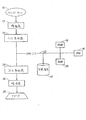
図1は、本発明の信号向上システムを実施するために使用することができる典型的な従来技術のプログラム可能な処理システムのブロック図である。音響信号はトランスデューサ・マイクロフォン10部で受け取られ、これが音響信号を表す対応電気信号を生成する。次いで、トランスデューサ・マイクロフォン10からの信号は、アナログ・デジタル・コンバータ14によってデジタル化する前に、増幅器12によって増幅するのが好ましい。アナログ・デジタル・コンバータ14の出力は、本発明の品質向上技法を適用する処理システムに加えられる。処理システムは、CPU16、RAM20、ROM18(フラッシュROMなど書き込み可能であってよい)、および図のようにCPUバス23によって結合された磁気ディスクなど任意選択の記憶装置22を含むのが好ましい。品質向上プロセスの出力は、ASRシステムなど他の処理システムに加えることも、ファイルに保存することも、聞き手のために再生することもできる。プレイバックは一般に、処理済みデジタル出力ストリームをデジタル・アナログ・コンバータ24によってアナログ信号に変換し、オーディオ・スピーカ28(たとえば、スピーカ、ヘッドホン、またはイヤホン)を駆動する出力増幅器26でそのアナログ信号を増幅することによって行う。
【0016】
システムの機能概観
以下、音響信号強調システムの機能構成要素について述べる。本発明の第1の機能構成要素は、入力データを時間−周波数表現に変換する動的な背景雑音推定器である。雑音推定器は、信号劣化を引き起こす連続的な、または緩やかに変わる背景雑音を推定する手段を提供する。雑音推定器はまた、雑音源が活動化された(たとえば、空調システムがオンまたはオフになった)場合など、雑音レベルの突然の変化に適応することができるべきである。動的背景雑音推定機能は、過渡的な音を背景雑音から分離し、背景雑音だけを推定することが可能である。一実施形態では、パワー検出器が複数の周波数帯域のそれぞれで動作する。データの雑音だけの部分を使用して、デシベル(dB)単位で雑音の平均および標準偏差を生成する。パワーが、周波数帯域内の指定数の標準偏差を超えて平均を上回った場合は、対応する時間は信号を含むものとして示され(flagged)、雑音だけのスペクトルを推定するために使用されない。
【0017】
動的背景雑音推定器は、第2の機能構成要素の過渡音検出器と密接に動作する。過渡音は、比較的短い時間内に音響パワーが上昇して下降するとき発生する。過渡音は発声された語音とすることができるが、衝撃音、ドアを激しく閉じる音など過渡的な雑音とすることもできる。過渡音の隔離は、過渡音を別々に調査し、信号事象と非信号事象に分類することを可能にする。また、新たな雑音源がオンになった場合など、パワー・レベルの上昇が永続的であるときを認識するのに有効である。これは、システムがその新たな雑音レベルに適応することを可能にする。
【0018】
本発明の第3の機能構成要素は信号検出器である。信号検出器は、非信号の非静的雑音を弁別するのに有効である。高調波の場合もまた、聞き手が再現信号を聞くことが望ましい場合にこれを使用してピッチ推定を行う。以下、雑音が存在する中で音声を検出する信号検出器の好ましい実施形態を述べる。音声検出器は、周波数領域内で声門パルス検出を使用する。データのスペクトログラムを生成し(信号の時間−周波数表現)、スペクトルの対数をとった後で、信号を周波数閾値まで時間軸に沿って合計する。得られた時系列の高い自己相関は、音声化された語音を表す。音声のピッチは、自己相関が最大になるラグである。
【0019】
第4の機能構成要素はスペクトル再スケーラである。入力信号は、弱いことも強いことも、近いことも遠いこともある。測定されたスペクトルをモデル内でテンプレートと整合する前に、パターン間の距離が信号の全音量に依存しないように測定されたスペクトルを再スケールする。好ましい実施形態では、重み付けがデシベル(dB)単位のSNRに比例する。重みは、それぞれ最小値および最大値によって下および上の境界となる。スペクトルは、記憶されたテンプレートそれぞれへの重み付けされた距離が最小になるように再スケールされる。
【0020】
第5の機能構成要素はパターン整合器である。テンプレートと測定されたスペクトルの間の距離は、ユークリッド距離または加重ユークリッド距離など、いくつかの適切な測定基準の1つとすることができる。測定されたスペクトルまでの最小距離を有するテンプレートが、最適な原型として選択される。信号モデルは、低雑音信号から得られた1組の短期間の原型スペクトログラムからなる。信号モデルの調整は、先に収集した原型から著しく異なるスペクトログラムを収集することによって行う。第1原型は、雑音より著しく上の信号を含む第1信号スペクトログラムである。後続の時間エポックについては、スペクトログラムが、選択された距離閾値より既存の原型に近い場合に、スペクトログラムを最も近い原型で平均化する。スペクトログラムが、選択された閾値より原型から離れている場合には、スペクトログラムを新しい原型として宣言する。
【0021】
第6の機能構成要素は低雑音スペクトログラム生成器である。低雑音スペクトログラムは、低SNRスペクトログラム・ビン内のデータを最適な原型の値で置き換えることにより、パターン整合器によって生成された雑音の多いスペクトログラムから生成される。高SNRスペクトログラム・ビンでは、測定されたスペクトルが変化しないままとされる。原型と測定された信号を混合したものが、中間SNRケースで使用される。
【0022】
第7の機能構成要素は再合成器である。出力信号は、低雑音スペクトログラムから再合成される。以下、好ましい一実施形態に移る。信号は、高調波部分と非高調波部分に分けられる。高調波部分の場合は、各成分について任意の初期位相が選択される。次いで、非ゼロ出力の各点について、各成分の振幅をスペクトログラムから補間し、基本周波数を信号検出器の出力から補間する。各成分を、それぞれ連続位相、振幅、およびその周波数間の高調波関係によって別々に合成する。高調波部分の出力は、成分の合計である。
【0023】
非高調波部分の場合は、再合成された時系列の基本周波数が、信号の基本周波数をたどる必要がない。一実施形態では、基本周波数を一定に保つことを除いて、高調波部分の場合のように連続振幅および位相再現を実行する。他の実施形態では、信号の各周波数帯域について1つずつ雑音生成器を使用し、振幅は、補間を介して低雑音スペクトログラムのものをたどっている。さらに他の実施形態では、バンドパス済み雑音の一定振幅ウィンドウを、その全振幅をその時点のスペクトログラムのものに調節した後で追加する。
【0024】
基本方法の概観
図2は、本発明の好ましい方法実施形態の流れ図である。図2に示す方法は、図1に示すアナログ・デジタル・コンバータ14からの出力として生成された複数のデータ・サンプルからなる着信音響信号を高品質化するために使用する。この方法は、「開始」状態で始まる(ステップ202)。着信データ・ストリーム(たとえば、先に生成された音響データ・ファイルまたはデジタル化された生音信号)が、1組のサンプルとしてコンピュータ・メモリ内に読み取られる(ステップ204)。好ましい実施形態では、本発明が通常、連続音響データ・ストリームの一部分を表すデータの「移動するウィンドウ」を高品質化するために適用されることになり、データ・ストリーム全体が処理される。一般に、高品質化すべき音響データ・ストリームは、元の音響データ・ストリームの期間にかかわらず、一連の固定長のデータ「バッファ」として表される。
【0025】
現在のウィンドウのサンプルは、事前フィルタ、シェーディングなど適切な条件付けオペレーションを含むことができる時間−周波数変換を受ける(ステップ206)。短時間フーリエ変換、フィルタ・バンク解析、離散ウェーブレット変換など、いくつかの時間−周波数変換のいずれかを使用することができる。
【0026】
時間−周波数変換の結果は、初期時系列x(t)が時間−周波数表現X(f,i)に変換されることであり、ただしtは時系列xのサンプリング・インデックス、fおよびiはそれぞれ、スペクトログラムXの周波数および時間次元を指し示す離散変数である。好ましい実施形態では、別途指定しない限り、後続のステップでXの代わりにXの大きさの対数を使用する(ステップ207)。すなわちP(f,i)=20log10(|X(f,i)|)
【0027】
時間および周波数に応じたパワー・レベルP(f,i)を、今後「スペクトログラム」と称する。
【0028】
次いで、個々の帯域f内のパワー・レベルが、過渡音隔離(ステップ210)と結合された背景雑音推定(ステップ208)を受ける。過渡音隔離は、静的雑音内に埋もれた過渡信号の存在を検出し、そのような過渡音の推定開始時間および終了時間を出力する。過渡音は探索信号のインスタンスとすることができるが、瞬間的雑音とすることもできる。背景雑音推定は、過渡音間で背景雑音パラメータの推定を更新する。
【0029】
背景雑音推定を実行するための好ましい実施形態は、各周波数帯域について移動するウィンドウ内の音響パワーを平均化するパワー検出器を含む。所定の数の周波数帯域内のパワーが、背景雑音より上で一定数の標準偏差として決められた閾値を上回った場合は、パワー検出器が信号の存在を宣言する。すなわち、次式のときである。
P(f,i)>B(f)+cσ(f)
ただし、B(f)は帯域f内の平均背景雑音パワー、σ(f)は同じ帯域内の雑音の標準偏差、cは定数である。代替実施形態では、雑音推定が動的である必要はなく、1回で測定できよう(たとえば、本発明を実施するソフトウェアが動作するコンピュータの起動中)。
【0030】
次いで、過渡音検出器を通過する変換済みデータが信号検出器機能に加えられる(ステップ212)。このステップは、信号と同じクラスでない過渡的雑音を弁別することを可能にする。語音(スピーチ)の高品質化の場合は、音声検出器をこのステップで適用する。具体的には、好ましい音声検出器では、レベルP(f,i)が最小および最大周波数、それぞれlowfおよびtopfの間で時間軸に沿って合計される。
【数1】

次いで、b(i)の自己相関を、τmaxpitch≦τ≦τminpitchのタイム・ラグτに応じて計算する。ただし、τmaxpitchは許容される最大音声ピッチに対応するラグであり、一方τminpitchは許容される最小音声ピッチに対応するラグである。音声/無音声の決定のために基づかれる統計値は、時間iで中心付けられたウィンドウ内で計算されるb(i)の正規化自己相関(自己相関係数)の値である。最大正規化自己相関が閾値より大きい場合は、音声を含むものと考えられる。この方法は、短時間スペクトログラム内に現れる声門パルスによって特徴付けられる、人の声の振動する性質を利用する。これらの声門パルスは、スペクトログラムの周波数次元に沿って並ぶ。音声が周波数の少なくとも何らかの領域を占めている場合は、合計の自己相関が、その音声に対応するピッチ期間の値で最大を示す。この音声検出方法の利点は、b(i)の自己相関係数が高くなるためにスペクトルの部分全体にわたってSNRが良好であることだけが必要であるため、スペクトルの大部分にわたって雑音妨害に強いことである。
【0032】
音声検出器の他の実施形態は、低SNRの周波数帯域ビンの影響を低減するため、スペクトログラム要素を合計する前に重み付けする。
【数2】
重みw(i)は、時間iの帯域f内のSNRr(f,i)に比例し、レベルの差、すなわち各周波数帯域についてr(f,i)=P(f,i)−B(f)で計算される。この実施形態では、再スケール係数の各要素が、以下のように定義される重みによって重み付けされる。ただし、wminおよびwmaxはプリセット閾値である。
w(f,i)=wmin、r(f,i)<wminの場合
w(f,i)=wmax、r(f,i)>wmaxの場合
w(f,i)=r(f,i)、その他の場合
【0034】
好ましい実施形態では、重みは、各時間枠で重みの合計によって正規化される。すなわち、
w’(f,i)=w(f,i)/sumf(w(f,i))
w’min=wmin/sumf(w(f,i))
w’max=wmax/sumf(w(f,i))
【0035】
次いで、ステップ208および210からのスペクトログラムPは、記憶されているテンプレートと比較できるように再スケールするのが好ましい(ステップ214)。このステップを実行する1つの方法は、スペクトログラムP(f,i)の各要素を定数k(i,m)で上げ、P(f,i)+k(i,m)と第m番目のテンプレートT(f,m)との間の平方2乗平均差が最低になるようにすることである。これは、以下をとることによって行う。ただし、Nは周波数帯域の数である。
【数3】
他の実施形態では、比較に先立ちテンプレートを再スケールする際に重み付けを使用する。
【数4】
このような再スケールの効果は、SNRの高いテンプレートの周波数帯域を優先的に整列させるためである。しかし、再スケールは任意選択であり、すべての実施形態で使用するには及ばない。
【0038】
他の実施形態では、テンプレートを再スケールするために、テンプレートのSNRならびに測定されたスペクトルのSNRが使用される。テンプレートT(f,m)のSNRは、rN(f,m)=T(f,m)−BN(f)で定義される。ただし、BN(f)は調整時の周波数帯域fの背景雑音である。rおよびrNを使用する重み付け方式の一実施形態では、重みwNが、テンプレートおよびスペクトログラムの重みの積の平方根と定義される。
【数5】
rNとrの他の組み合わせも許容可能である。好ましい実施形態では、重みは、各時間枠で重みの合計によって正規化される。すなわち
w’2(f,i)=w2(f,i)/sumf(w2(f,i))
w’min=wmin/sumf(w2(f,i))
w’max=wmax/sumf(w2(f,i))
【0040】
スペクトルの再スケール後、好ましい実施形態は、現在のスペクトログラムP(f,i)に最適に整合する信号モデル内のテンプレートT*を見つけるようにパターン整合を行う(ステップ216)。「最適整合」という用語の定義、ならびに最適整合を見つけるために使用する方法にはいくらかの自由度がある。一実施形態では、P+kとT*の間の最も小さいRMS(平方2乗平均)差d*を有するテンプレートを見つける。好ましい実施形態では、重み付けされたRMS距離を使用する。ただし、
【数6】
この実施形態では、最低SNRの周波数帯域は、より高いSNRの周波数帯域より距離計算への影響が少ない。時間iでの最適整合テンプレートT*(i)は、d*(i)=minm(d(i,m))となるようにmを見つけることによって選択される。
【0042】
次いで、低雑音スペクトログラムCが、選択された最も近いテンプレートT*に測定されたスペクトルPを合併することによって生成される(ステップ218)。各ウィンドウ位置iについて、低雑音スペクトログラムCがPおよびT*から再現される。好ましい実施形態では、以下の形で再現が行われる。各時間−周波数ビンについて、
C(f,i)=w’2(f,i)P(f,i)+[w’max−w’2(f,i)]T*(f,i)
【0043】
低雑音スペクトログラムCを生成した後で、低雑音出力時系列を合成する(ステップ220)。好ましい実施形態では、スペクトログラムが高調波(yh)と非高調波(yu)の部分に分けられ、各部が別々に再現される(y=yh+yu))。高調波部分は、一連の高調波c(t,j)を使用して合成される。任意の初期位相φ0(j)が各成分jについて選択される。次いで、各出力点yh(t)について各成分の大きさがスペクトログラムCから補間され、基本周波数f0が音声検出器の出力から補間される。成分c(t,j)は、それぞれ連続位相、振幅、および他の成分との共通ピッチ関係によって別々に合成される。すなわち
c(t,j)=A(t,j)sin[f0jt+φ0(j)]
ただし、A(t,j)は時間tでの各高調波jの振幅である。一実施形態は、スプライン補間を使用して、スペクトログラム点の間でなめらかに変わるf0およびA(t,j)の連続値を生成する。
【0044】
出力の高調波部分は、成分の合計yh(t)=sumj[c(t,j)]である。信号yuの非高調波部分の場合は、基本周波数が信号の基本周波数をたどる必要がない。一実施形態では、f0を一定に保つことを除いて、高調波部分の場合のように連続振幅および位相再現を実行する。他の実施形態では、信号の各周波数帯域について1つずつ雑音生成器を使用し、振幅は、低雑音スペクトログラムのものをたどるようにされる。
【0045】
いずれかの入力データが処理されていない場合は(ステップ222)、音響データの次のサンプルについてプロセス全体を繰り返す(ステップ204)。そうでない場合は処理が終了する(ステップ224)。最終出力は、元の入力音響信号の質向上を示す低雑音信号である。
【0046】
背景雑音推定および過渡音隔離
図3は、図2のステップ212および208としてそれぞれ簡単に述べた背景雑音推定および過渡音検出のプロセスをさらに詳しく述べた流れ図である。過渡音隔離プロセスは、静的雑音に埋もれた過渡信号の存在を検出する。背景雑音推定器は、過渡音間で背景雑音パラメータの推定を更新する。
【0047】
このプロセスは、「プロセス開始」状態で始まる(ステップ302)。このプロセスは、十分な数の背景雑音のサンプルを必要とし、それから雑音の平均および標準偏差を使用して過渡音を検出することができる。それゆえに、ルーチンは、十分な数の背景雑音のサンプルが得られているかどうかを判定する(ステップ304)。得られていない場合は、現在のサンプルを使用して雑音推定を更新し(ステップ306)、プロセスが修了する(ステップ320)。背景雑音更新プロセスの一実施形態では、スペクトログラム要素P(f,i)がリング・バッファ内に保たれ、各周波数帯域f内の雑音の平均B(f)および標準偏差σ(f)を更新するために使用される。背景雑音推定は、インデックスiがプリセット閾値より大きい場合に準備が整ったと見なす。
【0048】
背景雑音サンプルの準備が整った場合は(ステップ304)、信号レベルP(f,i)がいずれかの周波数帯域で背景雑音より著しく高いかどうかが判定される(ステップ308)。好ましい実施形態では、所定の数の周波数帯域内のパワーが、背景雑音平均レベルより上で一定数の標準偏差として決められた閾値より大きい場合に、判定ステップが、パワー閾値を上回ったことを示す。すなわち、次式のときである。
P(f,i)>B(f)+cσ(f)
ただし、cは経験的に所定の定数である。次いで、処理はステップ310で続く。
【0049】
スペクトログラム要素P(f,i)が過渡信号を含んでいるかどうかを判定するために、フラグ「In−possible−transient」が真にセットされ(ステップ310)、起こりうる過渡音の期間が増分される(ステップ312)。次いで、(起こりうる過渡音が)過渡音とするには長すぎるか否かが判定される(ステップ314)。可能な過渡期間がなおも最大期間内にある場合は、プロセスが終了する(ステップ320)。一方、過渡期間が長すぎて発声された言葉にならないと判断された場合は、背景雑音レベルの増加と考えられる。したがって、雑音推定が遡及的に更新され(ステップ316)、「In−possible−transient」フラグが偽にセットされ、かつ過渡期間が0にリセットされ(ステップ318)、処理が終了する(ステップ320)。
【0050】
ステップ308で十分強力な信号が検出されなかった場合は、背景雑音統計値がステップ306で更新される。その後で、「In−possible−transient」フラグがテストされる(ステップ322)。フラグが偽にセットされている場合はプロセスが終了する(ステップ320)。フラグが真にセットされている場合は、ステップ318のように偽にリセットされ、過渡期間が0にリセットされる。次いで過渡音の期間がテストされる(ステップ324)。過渡音が短すぎて発声された言葉の一部にならないと考えられる場合は、プロセスが終了する(ステップ320)。過渡音が、可能な発声された語音とするのに十分長い場合は、過渡フラグが真にセットされ、過渡音の開始および終了が呼出しルーチンに渡される(ステップ326)。次いでプロセスが終了する(ステップ320)。
【0051】
パターン整合
図4は、図2のステップ216として簡単に述べたパターン整合のプロセスをさらに詳しく述べた流れ図である。このプロセスは、「プロセス開始」状態で始まる(ステップ402)。パターン整合プロセスは、熟考されたスペクトログラムP(f,i)に最適に整合する信号モデル内のテンプレートT*を見つける(ステップ404)。パターン整合プロセスはまた、信号モデルの学習プロセスを受け持つ。「最適整合」という用語の定義、ならびに最適整合を見つけるために使用する方法にはいくらかの自由度がある。一実施形態では、P+kとT*の間の最も小さいRMS差d*を有するテンプレートを見つける。好ましい実施形態では、重み付けされたRMS距離を使用して整合の度合いを測定する。一実施形態では、RMSが次式によって計算される。
【数7】
この実施形態では、最低SNRの周波数帯域は、より高いSNRの周波数帯域より距離計算への影響が少ない。時間iでステップ404の出力である最適整合テンプレートT*(f,i)は、d*(i)=minm[d(i,m)]となるようにmを見つけることによって選択される。システムが学習モードでない場合は(ステップ406)、T*(f,i)は最も近いテンプレートとしてプロセスの出力でもある(ステップ408)。次いでプロセスが終了する(ステップ410)。
【0053】
システムが学習モードにある場合は(ステップ406)、P(f,i)に最も似ているテンプレートT*(f,i)が使用されて信号モデルが調節される。T*(f,i)がモデル内に組み込まれる方法は、d*(i)の値に応じて決まる(ステップ412)。dmaxが所定の閾値であり、d*(i)<dmaxの場合は、T*(f,i)が調節され(ステップ416)、プロセスが終了する(ステップ410)。ステップ416の好ましい実施形態は、T*(f,i)が、T*(f,i)を構成するために使用されるすべてのスペクトルP(f,i)の平均となるように実施される。好ましい実施形態では、T(f,m)に関連するスペクトルの数nmがメモリに保たれ、新たなスペクトルP(f,i)を使用してT(f,m)を調節する場合は、調節されたテンプレートが
T(f,m)=[nmT(f,m)+P(f,i)]/(nm+1)
であり、テンプレートmに対応するパターンの数も次のように調節される。
nm=nm+1
【0054】
ステップ412に戻り、d*(i)>dmaxの場合は、新しいテンプレートが作成され(ステップ414)(T*(f,i)=P(f,i)、重みnm=1)、プロセスが終了する(ステップ410)。
【0055】
コンピュータの実施
本発明は、ハードウェアでもソフトウェアでも、あるいは両方の組み合わせでも実施することができる(たとえば、プログラマブル・ロジック・アレイ)。別途指定しない限り、本発明の一部として含まれるアルゴリズムは、どの特定のコンピュータまたは他の装置にも本質的に関連付けられていない。具体的には、様々な汎用機を本明細書の教示に従って記述されたプログラムと共に使用することができ、あるいはより専用化された装置を構築して、必要とされる方法ステップを実行することがより好都合である可能性がある。しかし、本発明は、それぞれが少なくとも1つのプロセッサ、少なくとも1つのデータ記憶システム(揮発性および不揮発性メモリおよび/または記憶要素を含む)、少なくとも1つの入力装置、少なくとも1つの出力装置を備えるプログラム可能なシステム上で実行される1つまたは複数のコンピュータ・プログラム内で実施されることが好ましい。このようなプログラム可能なシステム構成要素はそれぞれ、一機能を実行するための手段を構成する。プログラム・コードはプロセッサ上で実行され、本明細書に記載された機能を実行する。
【0056】
このようなプログラムはそれぞれ、コンピュータ・システムと交信するために所望のコンピュータ言語(機械語、アセンブリ、上位手続き言語、オブジェクト指向プログラミング言語を含む)で実施することができる。いかなる場合でも、言語はコンパイラ型言語とすることもインタープリタ型言語とすることもできる。
【0057】
このようなコンピュータ・プログラムはそれぞれ、汎用または専用のプログラム可能なコンピュータ可読記憶媒体または装置(たとえば、ROM、CD−ROM、または磁気もしくは光媒体)上に記憶され、記憶媒体または装置がコンピュータによって読み取られた際にコンピュータを構成し、かつ動作させて、本明細書に記載された手順を実行することが好ましい。本発明のシステムはまた、コンピュータ・プログラムで構成されたコンピュータ可読記憶媒体として実施され、そのように構成された記憶媒体が、コンピュータを特定の事前定義された形で動作させて、本明細書に記載された機能を実行すると見なすことができる。
【0058】
以上、本発明のいくつかの実施形態について述べた。しかしながら、本発明の精神および範囲から逸脱することなく、様々な修正を加えることができることを理解されたい。たとえば、様々なアルゴリズムのいくつかのステップは順番に依存しないものとすることができ、したがって上述した以外の順番で実行することができる。それゆえに、他の実施形態が以下特許請求の範囲内にある。
【図面の簡単な説明】
【図1】 本発明の信号向上技法を実施するために適した従来技術のプログラム可能なコンピュータ・システムのブロック図である。
【図2】 本発明の好ましい実施形態の基本方法の流れ図である。
【図3】 入力データ内の過渡音を検出および隔離し、背景雑音パラメータを推定するための好ましい工程の流れ図である。
【図4】 信号モデル・テンプレートを生成および使用するための好ましい方法の流れ図である。[0001]
(Technical field)
The present invention relates to a system and method for enhancing the quality of an acoustic signal degraded by additive noise.
[0002]
(background)
There are several research fields that investigate the improvement of the quality of acoustic signals, with emphasis placed on speech signals. These include voice communication, automatic speech recognition (ASR), and hearing aids. Each research field adopts a unique method for improving the quality of acoustic signals, and there is some overlap between them.
[0003]
Acoustic signals are often degraded by the presence of noise. For example, in a busy office or a moving car, the performance of the ASR system is substantially degraded. When audio is transmitted to a remote listener, as in a teleconferencing system, the presence of noise can be uncomfortable and distracting for the listener, and it can also make speech difficult to understand. is there. Persons with hearing impairments are extremely difficult to understand speech in a noisy environment, and the total gain added to the signal by modern hearing aids does not help solve the problem. Old music records are often degraded by the presence of instantaneous noise or hissing. Other examples of communications that cause acoustic signal degradation due to noise include telephone calls, wireless communications, video conferencing, computer recording, and the like.
[0004]
The continuous large speech vocabulary ASR is particularly vulnerable to noise disturbances, and so far the solution adopted by the industry has been the use of headset microphones. Noise reduction is achieved by the proximity of the microphone and the subject's mouth (about 1.5 inches (38.1 mm)) and may be due to a special proximity effect microphone. However, the user often feels awkward to be bound to the computer by the headset and feels uncomfortable wearing a device that is severely noticeable. The need to use a headset hinders immediate human-machine interaction and is a significant barrier to market penetration of ASR technology.
[0005]
In addition to proximity microphones, conventional techniques for improving the quality of acoustic signals during communication have been adaptive filters and spectral subtraction. In the adaptive filter, the second microphone samples noise rather than signal. The noise is then subtracted from the signal. One problem with this approach is the cost of the second microphone that needs to be positioned at a different location than that used to pick up the important source. Furthermore, it is almost impossible to sample only the noise and not contain the desired source signal. Another form of adaptive filter applies a bandpass digital filter to the signal. The filter parameters are adapted to average the noise spectrum over time and maximize the signal-to-noise ratio (SNR). This method has the disadvantage that the signal is left behind in the low SNR band.
[0006]
In spectral subtraction, noise is estimated during periods of no signal and then subtracted from the signal spectrum when the signal is present. However, this causes the introduction of “musical noise” and other unnatural distortions. The root of these problems is that within a very low SNR region, spectral subtraction can only determine that the signal is below a certain level. By having to choose signal levels based on evidence that may be insufficient, considerable deviations from the true signal often occur in the form of noise and distortion.
[0007]
A recent approach to noise reduction is the use of beamforming using an array of microphones. This technique requires specialized hardware such as multiple microphones, A / D converters, and thus increases the cost of the system. Since the signal processing cost increases in proportion to the square of the number of microphones, the cost is also high. Another limitation of the microphone array is that some noise still leaks throughout the beamforming process. In addition, the actual array gain is usually higher than that measured in anechoic conditions or predicted from theory, since the echo and reverberation of the jamming source are still accepted through the main and side lobes of the array. Further lower.
[0008]
The inventor can improve the quality of an acoustic signal without leaving part of the spectrum, introducing unnatural noise, distorting the signal, or spending on the microphone array. Considered desirable. The present invention provides a system and method for acoustic signal enhancement that circumvents the limitations of the prior art.
[0009]
(Overview)
The present invention includes methods, apparatus, and computer programs for enhancing the quality of an acoustic signal by processing the input signal to produce an output signal with a very low level of noise ("signal" is a quality improvement) It means the target signal itself to be made, whereas the background sound and distracting sound are called “noise”). In the preferred embodiment, the quality is improved through the use of signal models that have been improved by learning. Although the input signal can represent a human speech, it should be understood that the present invention can be used to enhance any type of live or recorded sound data, such as musical instruments and birds and human voices.
[0010]
The preferred embodiment of the present invention emphasizes the input signal as follows. That is, the input signal is digitized into binary data converted to a time-frequency representation. Estimate background noise and isolate transient sounds. Apply signal detector to transient sound. Include long transients with no signal content and background noise between transients in noise estimation. If at least some part of the transient contains an important signal (target signal), the spectrum of the signal is compared with the signal model after rescaling and the signal parameters are matched to the data. The low noise signal is re-synthesized using the optimal set of signal model parameters. Since the signal model only incorporates a low noise signal, the output signal is also less noisy. If the template is significantly different from the existing template, the signal model is adjusted with low noise signal data by creating the template from the spectrogram. If an existing template is found to resemble an input pattern, the template is averaged with that pattern in such a way that the resulting template is the average of all spectra previously matched with that template. Thus, the knowledge of the signal characteristics built into the model works to converge the signal reproduction, thereby avoiding the introduction of unnatural noise or distortion.
[0011]
The present invention has the following advantages. That is, instantaneous and static noise-free recombined signal data can be output, only a single microphone is required as the source of the input signal, and the output signal in the low SNR region can be generated by the source It is kept consistent with the spectrum.
[0012]
The details of one or more embodiments of the invention are set forth in the accompanying drawings and the description below. Other features, objects, and advantages of the invention will be apparent from the description and drawings, and from the claims.
[0013]
Like reference numbers and designations in the various drawings indicate like elements.
[0014]
(Detailed explanation)
Throughout this description, the illustrated preferred embodiments and examples should not be construed as limiting the invention, but should be considered exemplary.
[0015]
Overview of operating environment
FIG. 1 is a block diagram of a typical prior art programmable processing system that can be used to implement the signal enhancement system of the present invention. The acoustic signal is received by the
[0016]
System functional overview
Hereinafter, functional components of the acoustic signal enhancement system will be described. The first functional component of the present invention is a dynamic background noise estimator that converts input data into a time-frequency representation. The noise estimator provides a means for estimating continuous or slowly changing background noise that causes signal degradation. The noise estimator should also be able to adapt to sudden changes in noise level, such as when a noise source is activated (eg, an air conditioning system is turned on or off). The dynamic background noise estimation function can separate the transient sound from the background noise and estimate only the background noise. In one embodiment, the power detector operates in each of a plurality of frequency bands. The noise-only part of the data is used to generate the noise mean and standard deviation in decibels (dB). If the power exceeds the average over a specified number of standard deviations in the frequency band, the corresponding time is flagged as containing the signal and is not used to estimate the noise-only spectrum.
[0017]
The dynamic background noise estimator works closely with the transient detector of the second functional component. A transient sound is generated when the sound power rises and falls within a relatively short time. Although the transient sound can be a spoken word sound, it can also be a transient noise such as an impact sound or a sound of closing the door violently. Transient sound isolation allows the transient sound to be examined separately and classified into signal and non-signal events. It is also useful for recognizing when the increase in power level is permanent, such as when a new noise source is turned on. This allows the system to adapt to the new noise level.
[0018]
The third functional component of the present invention is a signal detector. The signal detector is effective in discriminating non-signal non-static noise. In the case of harmonics, this is also used for pitch estimation when it is desirable for the listener to hear the reproduced signal. In the following, a preferred embodiment of a signal detector for detecting speech in the presence of noise will be described. Voice detectors use glottal pulse detection in the frequency domain. After generating a spectrogram of the data (time-frequency representation of the signal) and taking the logarithm of the spectrum, the signal is summed along the time axis to the frequency threshold. The obtained time-series high autocorrelation represents a voiced speech. The pitch of speech is the lag that maximizes autocorrelation.
[0019]
The fourth functional component is a spectrum rescaler. The input signal can be weak or strong, close or far. Before the measured spectrum is matched with the template in the model, the measured spectrum is rescaled so that the distance between patterns does not depend on the total volume of the signal. In the preferred embodiment, the weighting is proportional to the SNR in decibels (dB). The weights are at the lower and upper boundaries with minimum and maximum values, respectively. The spectrum is rescaled to minimize the weighted distance to each stored template.
[0020]
The fifth functional component is a pattern matching device. The distance between the template and the measured spectrum can be one of several suitable metrics, such as Euclidean distance or weighted Euclidean distance. The template with the smallest distance to the measured spectrum is selected as the optimal prototype. The signal model consists of a set of short-term prototype spectrograms obtained from low noise signals. The signal model is tuned by collecting spectrograms that differ significantly from the previously collected prototype. The first prototype is a first signal spectrogram that includes a signal significantly above the noise. For subsequent time epochs, if the spectrogram is closer to the existing prototype than the selected distance threshold, the spectrogram is averaged with the closest prototype. If the spectrogram is farther from the prototype than the selected threshold, declare the spectrogram as a new prototype.
[0021]
The sixth functional component is a low noise spectrogram generator. The low noise spectrogram is generated from the noisy spectrogram generated by the pattern matcher by replacing the data in the low SNR spectrogram bin with the optimal original values. With high SNR spectrogram bins, the measured spectrum remains unchanged. A mixture of the prototype and the measured signal is used in the intermediate SNR case.
[0022]
The seventh functional component is a re-synthesizer. The output signal is recombined from the low noise spectrogram. Hereinafter, the preferred embodiment will be described. The signal is divided into a harmonic part and a non-harmonic part. In the case of the harmonic part, an arbitrary initial phase is selected for each component. Then, for each point of non-zero output, the amplitude of each component is interpolated from the spectrogram and the fundamental frequency is interpolated from the output of the signal detector. Each component is synthesized separately by its continuous phase, amplitude, and harmonic relationship between its frequencies. The output of the harmonic part is the sum of the components.
[0023]
In the case of the non-harmonic part, the recombined time-series fundamental frequency does not need to follow the fundamental frequency of the signal. In one embodiment, continuous amplitude and phase reproduction is performed as in the harmonic portion except that the fundamental frequency is kept constant. In another embodiment, one noise generator is used for each frequency band of the signal, and the amplitude follows that of a low noise spectrogram via interpolation. In yet another embodiment, a constant amplitude window of bandpassed noise is added after adjusting its full amplitude to that of the current spectrogram.
[0024]
Overview of basic methods
FIG. 2 is a flow diagram of a preferred method embodiment of the present invention. The method shown in FIG. 2 is used to improve the quality of an incoming sound signal composed of a plurality of data samples generated as an output from the analog-to-
[0025]
The current window samples are subjected to a time-frequency transform that may include appropriate conditioning operations such as pre-filtering, shading, etc. (step 206). Any of several time-frequency transforms can be used, such as short-time Fourier transform, filter bank analysis, discrete wavelet transform.
[0026]
The result of the time-frequency transformation is that the initial time series x (t) is transformed into a time-frequency representation X (f, i), where t is the sampling index of the time series x and f and i are respectively , Discrete variables indicating the frequency and time dimensions of the spectrogram X. In the preferred embodiment, unless otherwise specified, the logarithm of the magnitude of X is used instead of X in subsequent steps (step 207). That is, P (f, i) = 20 log Ten (| X (f, i) |)
[0027]
The power level P (f, i) according to time and frequency is hereinafter referred to as “spectrogram”.
[0028]
The power levels within individual bands f are then subjected to background noise estimation (step 208) combined with transient sound isolation (step 210). Transient sound isolation detects the presence of a transient signal buried in static noise and outputs the estimated start and end times of such transient sound. Transient sounds can be instances of the search signal, but can also be instantaneous noise. Background noise estimation updates background noise parameter estimates between transients.
[0029]
A preferred embodiment for performing background noise estimation includes a power detector that averages the acoustic power in a moving window for each frequency band. If the power in a predetermined number of frequency bands exceeds a threshold determined as a certain number of standard deviations above background noise, the power detector declares the presence of a signal. That is, the following equation.
P (f, i)> B (f) + cσ (f)
Where B (f) is the average background noise power in the band f, σ (f) is the standard deviation of noise in the same band, and c is a constant. In alternative embodiments, noise estimation need not be dynamic and could be measured at once (eg, during startup of a computer running software implementing the present invention).
[0030]
The converted data passing through the transient sound detector is then added to the signal detector function (step 212). This step makes it possible to discriminate transient noise that is not in the same class as the signal. In the case of improving the quality of speech (speech), a speech detector is applied at this step. Specifically, in the preferred speech detector, the level P (f, i) is summed along the time axis between the minimum and maximum frequencies, lowf and topf, respectively.
[Expression 1]
Then the autocorrelation of b (i) is maxpitch ≦ τ ≦ τ minpitch Is calculated according to the time lag τ. Where τ maxpitch Is the lag corresponding to the maximum allowed voice pitch, while τ minpitch Is the lag corresponding to the minimum allowed voice pitch. The statistical value based on the voice / no-voice decision is the value of the normalized autocorrelation (autocorrelation coefficient) of b (i) calculated in the window centered at time i. If the maximum normalized autocorrelation is greater than the threshold, it is considered to include speech. This method takes advantage of the vibrating nature of the human voice, characterized by glottal pulses that appear in the short-time spectrogram. These glottal pulses line up along the frequency dimension of the spectrogram. If the speech occupies at least some region of frequency, the total autocorrelation shows the maximum value for the pitch period corresponding to that speech. The advantage of this speech detection method is that it is resistant to noise jamming over the majority of the spectrum since it only needs to have good SNR over the whole part of the spectrum due to the high autocorrelation coefficient of b (i). It is.
[0032]
Other embodiments of the speech detector weight the spectrogram elements before summing to reduce the effects of low SNR frequency band bins.
[Expression 2]
The weight w (i) is proportional to the SNRr (f, i) in the band f at time i, and the level difference, ie, r (f, i) = P (f, i) −B (f) for each frequency band. ). In this embodiment, each element of the rescaling factor is weighted by a weight defined as follows: However, w min And w max Is a preset threshold.
w (f, i) = w min , R (f, i) <w min in the case of
w (f, i) = w max , R (f, i)> w max in the case of
w (f, i) = r (f, i), other cases
[0034]
In the preferred embodiment, the weights are normalized by the sum of the weights in each time frame. That is,
w ′ (f, i) = w (f, i) / sum f (W (f, i))
w ' min = W min / Sum f (W (f, i))
w ' max = W max / Sum f (W (f, i))
[0035]
The spectrogram P from
[Equation 3]
In other embodiments, weighting is used when rescaling the template prior to the comparison.
[Expression 4]
The effect of such rescaling is to preferentially align the frequency band of the template having a high SNR. However, rescaling is optional and not sufficient for use in all embodiments.
[0038]
In other embodiments, the SNR of the template as well as the SNR of the measured spectrum are used to rescale the template. The SNR of the template T (f, m) is r N (F, m) = T (f, m) -B N Defined in (f). However, B N (F) is the background noise of the frequency band f at the time of adjustment. r and r N In one embodiment of a weighting scheme that uses N Is defined as the square root of the product of the template and spectrogram weights.
[Equation 5]
r N Other combinations of and r are also acceptable. In the preferred embodiment, the weights are normalized by the sum of the weights in each time frame. Ie
w ' 2 (F, i) = w 2 (F, i) / sum f (W 2 (F, i))
w ' min = W min / Sum f (W 2 (F, i))
w ' max = W max / Sum f (W 2 (F, i))
[0040]
After re-scaling the spectrum, the preferred embodiment is the template T in the signal model that best matches the current spectrogram P (f, i). * Pattern matching is performed so as to find (step 216). There is some flexibility in the definition of the term “optimum match”, as well as the method used to find the best match. In one embodiment, P + k and T * Smallest RMS (root mean square) difference d between * Find a template with In the preferred embodiment, a weighted RMS distance is used. However,
[Formula 6]
In this embodiment, the lowest SNR frequency band has less impact on the distance calculation than the higher SNR frequency band. Optimal matching template T at time i * (I) is d * (I) = min m It is selected by finding m to be (d (i, m)).
[0042]
The low noise spectrogram C is then selected as the closest template T selected. * Is generated by merging the measured spectrum P (step 218). For each window position i, the low noise spectrogram C is P and T * It is reproduced from. In the preferred embodiment, the reproduction is performed in the following manner. For each time-frequency bin
C (f, i) = w ′ 2 (F, i) P (f, i) + [w ′ max −w ′ 2 (F, i)] T * (F, i)
[0043]
After generating the low noise spectrogram C, a low noise output time series is synthesized (step 220). In a preferred embodiment, the spectrogram is harmonic (y h ) And non-harmonic (y u ) And each part is reproduced separately (y = y h + Y u )). The harmonic part is synthesized using a series of harmonics c (t, j). Arbitrary initial phase φ 0 (J) is selected for each component j. Next, each output point y h For (t), the magnitude of each component is interpolated from the spectrogram C and the fundamental frequency f 0 Is interpolated from the output of the speech detector. The components c (t, j) are synthesized separately by the continuous phase, amplitude, and common pitch relationship with other components, respectively. Ie
c (t, j) = A (t, j) sin [f 0 jt + φ 0 (J)]
However, A (t, j) is the amplitude of each harmonic j at time t. One embodiment uses spline interpolation to smoothly change between spectrogram points f 0 And a continuous value of A (t, j).
[0044]
The harmonic part of the output is the sum of the components y h (T) = sum j [C (t, j)]. Signal y u In the case of the non-harmonic part, the fundamental frequency does not need to follow the fundamental frequency of the signal. In one embodiment, f 0 Is performed, as in the case of the harmonic part, with continuous amplitude and phase reproduction. In other embodiments, one noise generator is used for each frequency band of the signal, and the amplitude is made to follow that of a low noise spectrogram.
[0045]
If any input data has not been processed (step 222), the entire process is repeated for the next sample of acoustic data (step 204). Otherwise, the process ends (step 224). The final output is a low noise signal that indicates an improvement in the quality of the original input acoustic signal.
[0046]
Background noise estimation and transient sound isolation
FIG. 3 is a flow chart detailing the background noise estimation and transient detection process briefly described as
[0047]
The process begins in a “process start” state (step 302). This process requires a sufficient number of background noise samples, from which the noise mean and standard deviation can be used to detect transient sounds. Therefore, the routine determines whether a sufficient number of background noise samples have been obtained (step 304). If not, the noise estimate is updated using the current sample (step 306) and the process ends (step 320). In one embodiment of the background noise update process, the spectrogram element P (f, i) is kept in the ring buffer to update the mean B (f) and standard deviation σ (f) of the noise in each frequency band f. Used for. Background noise estimation considers ready when index i is greater than a preset threshold.
[0048]
When the background noise sample is ready (step 304), it is determined whether the signal level P (f, i) is significantly higher than the background noise in any frequency band (step 308). In a preferred embodiment, the determination step indicates that the power has exceeded the power threshold when the power in the predetermined number of frequency bands is greater than a threshold determined as a certain number of standard deviations above the background noise average level. . That is, the following equation.
P (f, i)> B (f) + cσ (f)
However, c is a predetermined constant empirically. Processing then continues at
[0049]
To determine whether the spectrogram element P (f, i) contains a transient signal, the flag “In-possible-transient” is set to true (step 310) and the duration of the possible transient sound is incremented. (Step 312). It is then determined whether the (possible transient) is too long to be a transient (step 314). If the possible transition period is still within the maximum period, the process ends (step 320). On the other hand, if it is determined that the transition period is too long to become a spoken word, it is considered that the background noise level is increased. Accordingly, the noise estimate is updated retroactively (step 316), the “In-possible-transient” flag is set to false, the transient period is reset to 0 (step 318), and the process ends (step 320). .
[0050]
If a sufficiently strong signal is not detected at
[0051]
Pattern matching
FIG. 4 is a flowchart detailing the process of pattern matching, briefly described as
[Expression 7]
In this embodiment, the lowest SNR frequency band has less impact on the distance calculation than the higher SNR frequency band. Optimal matching template T which is the output of
[0053]
If the system is in learning mode (step 406), the template T most similar to P (f, i) * (F, i) is used to adjust the signal model. T * The way (f, i) is incorporated into the model is d * It is determined according to the value of (i) (step 412). d max Is a predetermined threshold and d * (I) <d max In the case of T * (F, i) is adjusted (step 416) and the process ends (step 410). A preferred embodiment of
T (f, m) = [n m T (f, m) + P (f, i)] / (n m +1)
And the number of patterns corresponding to the template m is also adjusted as follows.
n m = N m +1
[0054]
Return to step 412 and d * (I)> d max In the case of, a new template is created (step 414) (T * (F, i) = P (f, i), weight n m = 1), the process ends (step 410).
[0055]
Computer implementation
The invention can be implemented in hardware or software, or a combination of both (eg, programmable logic arrays). Unless otherwise specified, the algorithms included as part of the present invention are not inherently associated with any particular computer or other apparatus. In particular, various general purpose machines can be used with programs described in accordance with the teachings herein, or more specialized devices can be constructed to perform the required method steps. It may be more convenient. However, the present invention is programmable with at least one processor, at least one data storage system (including volatile and non-volatile memory and / or storage elements), at least one input device, and at least one output device, respectively. Preferably, it is implemented within one or more computer programs running on a secure system. Each such programmable system component constitutes a means for performing a function. Program code is executed on the processor to perform the functions described herein.
[0056]
Each such program can be implemented in any desired computer language (including machine language, assembly, high-level procedural language, and object-oriented programming language) to communicate with the computer system. In any case, the language can be a compiled language or an interpreted language.
[0057]
Each such computer program is stored on a general purpose or special purpose programmable computer readable storage medium or device (eg, ROM, CD-ROM, or magnetic or optical media), and the storage medium or device is read by a computer. Preferably, the computer is configured and operated when executed to perform the procedures described herein. The system of the present invention is also implemented as a computer readable storage medium configured with a computer program, which causes the computer to operate in a specific predefined manner herein. It can be considered to perform the described function.
[0058]
In the above, several embodiments of the present invention have been described. However, it should be understood that various modifications can be made without departing from the spirit and scope of the invention. For example, some steps of the various algorithms may be order independent and thus can be performed in an order other than those described above. Accordingly, other embodiments are within the scope of the following claims.
[Brief description of the drawings]
FIG. 1 is a block diagram of a prior art programmable computer system suitable for implementing the signal enhancement techniques of the present invention.
FIG. 2 is a flow diagram of the basic method of the preferred embodiment of the present invention.
FIG. 3 is a flow diagram of a preferred process for detecting and isolating transients in input data and estimating background noise parameters.
FIG. 4 is a flow diagram of a preferred method for generating and using a signal model template.
Claims (21)
該方法は、
雑音のある入力信号の時間−周波数表現を決定することと、
背景雑音レベルと信号対雑音比とを推定することと、
該時間−周波数表現に対する整合低雑音信号テンプレートを決定することと、
該時間−周波数表現の一部を、該時間−周波数表現と該整合低雑音信号テンプレートとの混合に置き換えることであって、該混合は、該信号対雑音比によって重み付けられている、ことと
を包含する、方法。A method for enhancing an input signal,
The method
Determining a time-frequency representation of the noisy input signal;
Estimating the background noise level and signal-to-noise ratio;
Determining a matched low noise signal template for the time-frequency representation;
Replacing a portion of the time-frequency representation with a mixture of the time-frequency representation and the matched low noise signal template, the mixture being weighted by the signal-to-noise ratio; The method of inclusion.
学習モードがアクティブであるか非アクティブであるかを決定することをさらに包含し、
前記置き換えることが、
該学習モードが非アクティブである場合に、デジタル化された入力信号の一部を、前記時間−周波数表現と前記整合低雑音信号テンプレートとの信号対雑音比で重み付けられた混合に置き換えることをさらに包含する、請求項6に記載の方法。The method comprises
Further comprising determining whether the learning mode is active or inactive;
Said replacing,
Further replacing a portion of the digitized input signal with a weighted signal-to-noise ratio of the time-frequency representation and the matched low-noise signal template when the learning mode is inactive; The method of claim 6 comprising.
該プロセッサに結合されたメモリと
を備えた信号強調システムであって、
該メモリは、命令を含み、
該命令は、
複数の低雑音信号テンプレートを含む信号モデルを確立することと、
入力信号を取得することと、
該入力信号に対する該信号モデル内の整合低雑音信号テンプレートを決定することと、
該入力信号の一部を、該入力信号と該整合低雑音信号テンプレートとの信号対雑音比で重み付けられた混合に置き換えることと
を該プロセッサに行わせる、システム。A processor;
A signal enhancement system comprising: a memory coupled to the processor;
The memory includes instructions;
The instruction is
Establishing a signal model including a plurality of low noise signal templates ;
Obtaining an input signal ;
Determining a matched low noise signal template in the signal model for the input signal ;
A part of the input signal, and Rukoto replaced with mixed weighted by the signal-to-noise ratio of the input signal and該整if low noise signal template
A system for causing the processor to perform .
前記整合低雑音信号テンプレートを決定することを該プロセッサに行わせる命令は、整合低雑音スペクトログラムテンプレートを決定することを該プロセッサに行わせ、
前記入力信号の一部を置き換えることを該プロセッサに行わせる命令は、該入力信号スペクトログラムの一部を入力信号スペクトルと該整合低雑音スペクトログラムテンプレートとの信号対雑音比で重み付けられた混合に置き換えることによって、低雑音スペクトログラムを生成することを該プロセッサに行わせる、請求項10に記載のシステム。The memory further includes instructions for performing the determining the input signal spectrogram of the input signal to said processor,
Instructions for causing the determining of the matching low noise signal template to said processor, to perform determining a matching low noise spectrogram templates in the processor,
Instructions for causing a obtaining replace a portion of the input signal to the processor, the mixture weighted by signal-to-noise ratio of the part of the input signal spectrum and該整if low noise spectrogram template of the input signal spectrogram The system of claim 10 , wherein replacing causes the processor to generate a low noise spectrogram.
該命令は、
複数の低雑音信号テンプレートを含む信号モデルから雑音のある入力信号に対する整合低雑音信号テンプレートを決定することと、
該入力信号の一部を該入力信号と該整合低雑音信号テンプレートとの信号対雑音比で重み付けられた混合に置き換えることと
をプロセッサに行わせる、コンピュータ読み取り可能な格納媒体。 Instruction is a recorded computer-readable storage medium body,
The instruction is
Determining a matched low noise signal template for a noisy input signal from a signal model including a plurality of low noise signal templates ;
And possible to obtain replace a portion of the input signal to the mixing weighted by signal-to-noise ratio of the input signal and該整if low noise signal template
A computer-readable storage medium that causes a processor to perform the above .
前記整合低雑音信号テンプレートを決定する命令は、
該入力信号スペクトログラムと前記複数の低雑音信号テンプレートの各々との間の信号対雑音比で重み付けられた距離を決定することと、
該整合低雑音信号テンプレートとして、該信号対雑音比で重み付けられた距離のうちの最小の距離を有する該信号モデル内の低雑音信号テンプレートを選択することと
を該プロセッサに行わせ、それによって、該雑音のある入力信号における周波数帯域は、当該周波数帯域の信号対雑音比に比例して、該信号対雑音比で重み付けられた距離に寄与する、請求項17に記載のコンピュータ読み取り可能な格納媒体。The instructions further carry out the processor to determine the input signal spectrogram of the input signal with the noise,
The instructions for determining the matched low noise signal template are:
Determining a weighted distance in signal to noise ratio between the input signal spectrogram and each of the plurality of low noise signal templates ;
As該整if low noise signal template, and selecting a low noise signal template in the signal model having the smallest distance among distances weighted by the signal-to-noise ratio was made to the processor, whereby, The computer-readable storage medium of claim 17, wherein a frequency band in the noisy input signal contributes to a distance weighted by the signal-to-noise ratio in proportion to the signal-to-noise ratio of the frequency band. .
前記雑音のある入力信号における過渡現象を検索することと、
該過渡現象が存在しない場合に背景雑音推定を更新することと、
該過渡現象の検出の後、前記整合低雑音信号テンプレートを決定し、該入力信号の一部を置き換えることと
を前記プロセッサに行わせる命令をさらに格納する、請求項17に記載のコンピュータ読み取り可能な格納媒体。The medium,
Searching for transients in the noisy input signal ;
Updating the background noise estimate when the transient does not exist ;
After the detection of the transient phenomenon, to determine the matching low noise signal template, further storing instructions for causing a possible to obtain replace a portion of the input signal to the processor, computer readable of claim 17 Possible storage medium .
Applications Claiming Priority (3)
| Application Number | Priority Date | Filing Date | Title |
|---|---|---|---|
| US09/375,309 | 1999-08-16 | ||
| US09/375,309 US6910011B1 (en) | 1999-08-16 | 1999-08-16 | Noisy acoustic signal enhancement |
| PCT/US2000/022201 WO2001013364A1 (en) | 1999-08-16 | 2000-08-11 | Method for enhancement of acoustic signal in noise |
Publications (3)
| Publication Number | Publication Date |
|---|---|
| JP2003507764A JP2003507764A (en) | 2003-02-25 |
| JP2003507764A5 JP2003507764A5 (en) | 2007-09-20 |
| JP4764995B2 true JP4764995B2 (en) | 2011-09-07 |
Family
ID=23480366
Family Applications (1)
| Application Number | Title | Priority Date | Filing Date |
|---|---|---|---|
| JP2001517379A Expired - Lifetime JP4764995B2 (en) | 1999-08-16 | 2000-08-11 | Improve the quality of acoustic signals including noise |
Country Status (8)
| Country | Link |
|---|---|
| US (2) | US6910011B1 (en) |
| EP (1) | EP1208563B1 (en) |
| JP (1) | JP4764995B2 (en) |
| AT (1) | ATE323937T1 (en) |
| AU (1) | AU6769600A (en) |
| CA (1) | CA2382175C (en) |
| DE (1) | DE60027438T2 (en) |
| WO (1) | WO2001013364A1 (en) |
Families Citing this family (74)
| Publication number | Priority date | Publication date | Assignee | Title |
|---|---|---|---|---|
| US6910011B1 (en) * | 1999-08-16 | 2005-06-21 | Haman Becker Automotive Systems - Wavemakers, Inc. | Noisy acoustic signal enhancement |
| US7117149B1 (en) | 1999-08-30 | 2006-10-03 | Harman Becker Automotive Systems-Wavemakers, Inc. | Sound source classification |
| GB2379114A (en) * | 2001-08-21 | 2003-02-26 | Sony Uk Ltd | Introducing test signals into a data signal |
| US7889879B2 (en) | 2002-05-21 | 2011-02-15 | Cochlear Limited | Programmable auditory prosthesis with trainable automatic adaptation to acoustic conditions |
| US7103541B2 (en) * | 2002-06-27 | 2006-09-05 | Microsoft Corporation | Microphone array signal enhancement using mixture models |
| KR100463657B1 (en) * | 2002-11-30 | 2004-12-29 | 삼성전자주식회사 | Apparatus and method of voice region detection |
| US7895036B2 (en) * | 2003-02-21 | 2011-02-22 | Qnx Software Systems Co. | System for suppressing wind noise |
| US8271279B2 (en) | 2003-02-21 | 2012-09-18 | Qnx Software Systems Limited | Signature noise removal |
| US7885420B2 (en) * | 2003-02-21 | 2011-02-08 | Qnx Software Systems Co. | Wind noise suppression system |
| US8326621B2 (en) | 2003-02-21 | 2012-12-04 | Qnx Software Systems Limited | Repetitive transient noise removal |
| US8073689B2 (en) | 2003-02-21 | 2011-12-06 | Qnx Software Systems Co. | Repetitive transient noise removal |
| US7725315B2 (en) * | 2003-02-21 | 2010-05-25 | Qnx Software Systems (Wavemakers), Inc. | Minimization of transient noises in a voice signal |
| US7949522B2 (en) | 2003-02-21 | 2011-05-24 | Qnx Software Systems Co. | System for suppressing rain noise |
| GB2398913B (en) * | 2003-02-27 | 2005-08-17 | Motorola Inc | Noise estimation in speech recognition |
| WO2004084181A2 (en) * | 2003-03-15 | 2004-09-30 | Mindspeed Technologies, Inc. | Simple noise suppression model |
| US7620546B2 (en) * | 2004-03-23 | 2009-11-17 | Qnx Software Systems (Wavemakers), Inc. | Isolating speech signals utilizing neural networks |
| JP4318119B2 (en) * | 2004-06-18 | 2009-08-19 | 国立大学法人京都大学 | Acoustic signal processing method, acoustic signal processing apparatus, acoustic signal processing system, and computer program |
| US8306821B2 (en) | 2004-10-26 | 2012-11-06 | Qnx Software Systems Limited | Sub-band periodic signal enhancement system |
| US7716046B2 (en) * | 2004-10-26 | 2010-05-11 | Qnx Software Systems (Wavemakers), Inc. | Advanced periodic signal enhancement |
| US7610196B2 (en) * | 2004-10-26 | 2009-10-27 | Qnx Software Systems (Wavemakers), Inc. | Periodic signal enhancement system |
| US8170879B2 (en) * | 2004-10-26 | 2012-05-01 | Qnx Software Systems Limited | Periodic signal enhancement system |
| US7949520B2 (en) | 2004-10-26 | 2011-05-24 | QNX Software Sytems Co. | Adaptive filter pitch extraction |
| US7680652B2 (en) * | 2004-10-26 | 2010-03-16 | Qnx Software Systems (Wavemakers), Inc. | Periodic signal enhancement system |
| US8543390B2 (en) * | 2004-10-26 | 2013-09-24 | Qnx Software Systems Limited | Multi-channel periodic signal enhancement system |
| KR100657912B1 (en) * | 2004-11-18 | 2006-12-14 | 삼성전자주식회사 | Noise reduction method and apparatus |
| US8284947B2 (en) * | 2004-12-01 | 2012-10-09 | Qnx Software Systems Limited | Reverberation estimation and suppression system |
| US7415164B2 (en) * | 2005-01-05 | 2008-08-19 | Mitsubishi Electric Research Laboratories, Inc. | Modeling scenes in videos using spectral similarity |
| US7742914B2 (en) * | 2005-03-07 | 2010-06-22 | Daniel A. Kosek | Audio spectral noise reduction method and apparatus |
| US8027833B2 (en) | 2005-05-09 | 2011-09-27 | Qnx Software Systems Co. | System for suppressing passing tire hiss |
| US8170875B2 (en) | 2005-06-15 | 2012-05-01 | Qnx Software Systems Limited | Speech end-pointer |
| US8311819B2 (en) | 2005-06-15 | 2012-11-13 | Qnx Software Systems Limited | System for detecting speech with background voice estimates and noise estimates |
| JP4765461B2 (en) * | 2005-07-27 | 2011-09-07 | 日本電気株式会社 | Noise suppression system, method and program |
| US8204754B2 (en) * | 2006-02-10 | 2012-06-19 | Telefonaktiebolaget L M Ericsson (Publ) | System and method for an improved voice detector |
| US7720681B2 (en) * | 2006-03-23 | 2010-05-18 | Microsoft Corporation | Digital voice profiles |
| US7844453B2 (en) | 2006-05-12 | 2010-11-30 | Qnx Software Systems Co. | Robust noise estimation |
| US9462118B2 (en) * | 2006-05-30 | 2016-10-04 | Microsoft Technology Licensing, Llc | VoIP communication content control |
| US8971217B2 (en) * | 2006-06-30 | 2015-03-03 | Microsoft Technology Licensing, Llc | Transmitting packet-based data items |
| DE602006005684D1 (en) * | 2006-10-31 | 2009-04-23 | Harman Becker Automotive Sys | Model-based improvement of speech signals |
| US8335685B2 (en) * | 2006-12-22 | 2012-12-18 | Qnx Software Systems Limited | Ambient noise compensation system robust to high excitation noise |
| US8326620B2 (en) | 2008-04-30 | 2012-12-04 | Qnx Software Systems Limited | Robust downlink speech and noise detector |
| US20080181392A1 (en) * | 2007-01-31 | 2008-07-31 | Mohammad Reza Zad-Issa | Echo cancellation and noise suppression calibration in telephony devices |
| RU2440627C2 (en) | 2007-02-26 | 2012-01-20 | Долби Лэборетериз Лайсенсинг Корпорейшн | Increasing speech intelligibility in sound recordings of entertainment programmes |
| JP5791092B2 (en) * | 2007-03-06 | 2015-10-07 | 日本電気株式会社 | Noise suppression method, apparatus, and program |
| US8280731B2 (en) * | 2007-03-19 | 2012-10-02 | Dolby Laboratories Licensing Corporation | Noise variance estimator for speech enhancement |
| US20080231557A1 (en) * | 2007-03-20 | 2008-09-25 | Leadis Technology, Inc. | Emission control in aged active matrix oled display using voltage ratio or current ratio |
| US20080274705A1 (en) * | 2007-05-02 | 2008-11-06 | Mohammad Reza Zad-Issa | Automatic tuning of telephony devices |
| US7885810B1 (en) * | 2007-05-10 | 2011-02-08 | Mediatek Inc. | Acoustic signal enhancement method and apparatus |
| EP1995722B1 (en) | 2007-05-21 | 2011-10-12 | Harman Becker Automotive Systems GmbH | Method for processing an acoustic input signal to provide an output signal with reduced noise |
| CN101320559B (en) * | 2007-06-07 | 2011-05-18 | 华为技术有限公司 | Sound activation detection apparatus and method |
| WO2008154706A1 (en) | 2007-06-20 | 2008-12-24 | Cochlear Limited | A method and apparatus for optimising the control of operation of a hearing prosthesis |
| US8489396B2 (en) * | 2007-07-25 | 2013-07-16 | Qnx Software Systems Limited | Noise reduction with integrated tonal noise reduction |
| US8904400B2 (en) * | 2007-09-11 | 2014-12-02 | 2236008 Ontario Inc. | Processing system having a partitioning component for resource partitioning |
| US8850154B2 (en) | 2007-09-11 | 2014-09-30 | 2236008 Ontario Inc. | Processing system having memory partitioning |
| CN101802909B (en) * | 2007-09-12 | 2013-07-10 | 杜比实验室特许公司 | Speech enhancement with noise level estimation adjustment |
| US8694310B2 (en) | 2007-09-17 | 2014-04-08 | Qnx Software Systems Limited | Remote control server protocol system |
| DE602007004504D1 (en) * | 2007-10-29 | 2010-03-11 | Harman Becker Automotive Sys | Partial language reconstruction |
| US8209514B2 (en) * | 2008-02-04 | 2012-06-26 | Qnx Software Systems Limited | Media processing system having resource partitioning |
| KR101335417B1 (en) * | 2008-03-31 | 2013-12-05 | (주)트란소노 | Procedure for processing noisy speech signals, and apparatus and program therefor |
| CA2750241C (en) * | 2009-01-20 | 2015-06-16 | Widex A/S | A hearing aid and a method of detecting and attenuating transients |
| FR2948484B1 (en) * | 2009-07-23 | 2011-07-29 | Parrot | METHOD FOR FILTERING NON-STATIONARY SIDE NOISES FOR A MULTI-MICROPHONE AUDIO DEVICE, IN PARTICULAR A "HANDS-FREE" TELEPHONE DEVICE FOR A MOTOR VEHICLE |
| JP5417099B2 (en) * | 2009-09-14 | 2014-02-12 | 株式会社東京建設コンサルタント | A method for evaluating the state of structures by measuring ultra-low frequency sound |
| US20110134773A1 (en) * | 2009-12-04 | 2011-06-09 | Electronics And Telecommunications Research Institute | Method and apparatus for estimating propagation delay time |
| US8390514B1 (en) * | 2010-01-11 | 2013-03-05 | The Boeing Company | Detection and geolocation of transient signals received by multi-beamforming antenna |
| US8913758B2 (en) * | 2010-10-18 | 2014-12-16 | Avaya Inc. | System and method for spatial noise suppression based on phase information |
| US20120143604A1 (en) * | 2010-12-07 | 2012-06-07 | Rita Singh | Method for Restoring Spectral Components in Denoised Speech Signals |
| US9589580B2 (en) * | 2011-03-14 | 2017-03-07 | Cochlear Limited | Sound processing based on a confidence measure |
| US8990074B2 (en) * | 2011-05-24 | 2015-03-24 | Qualcomm Incorporated | Noise-robust speech coding mode classification |
| US9143107B2 (en) * | 2013-10-08 | 2015-09-22 | 2236008 Ontario Inc. | System and method for dynamically mixing audio signals |
| US9721580B2 (en) * | 2014-03-31 | 2017-08-01 | Google Inc. | Situation dependent transient suppression |
| US9552829B2 (en) * | 2014-05-01 | 2017-01-24 | Bellevue Investments Gmbh & Co. Kgaa | System and method for low-loss removal of stationary and non-stationary short-time interferences |
| CN105261375B (en) * | 2014-07-18 | 2018-08-31 | 中兴通讯股份有限公司 | Activate the method and device of sound detection |
| US9812149B2 (en) * | 2016-01-28 | 2017-11-07 | Knowles Electronics, Llc | Methods and systems for providing consistency in noise reduction during speech and non-speech periods |
| US10249319B1 (en) | 2017-10-26 | 2019-04-02 | The Nielsen Company (Us), Llc | Methods and apparatus to reduce noise from harmonic noise sources |
| CN108470476B (en) * | 2018-05-15 | 2020-06-30 | 黄淮学院 | English pronunciation matching correction system |
Citations (10)
| Publication number | Priority date | Publication date | Assignee | Title |
|---|---|---|---|---|
| JPH04257898A (en) * | 1991-02-13 | 1992-09-14 | Sharp Corp | Lombard voice recognizing method |
| JPH0573090A (en) * | 1991-09-18 | 1993-03-26 | Fujitsu Ltd | Speech recognizing method |
| JPH07261800A (en) * | 1994-03-17 | 1995-10-13 | Nippon Telegr & Teleph Corp <Ntt> | Transformation encoding method, decoding method |
| JPH08223052A (en) * | 1995-02-17 | 1996-08-30 | Victor Co Of Japan Ltd | Voice high efficiency coding device |
| JPH09212196A (en) * | 1996-01-31 | 1997-08-15 | Nippon Telegr & Teleph Corp <Ntt> | Noise suppressor |
| JPH09258783A (en) * | 1996-03-26 | 1997-10-03 | Mitsubishi Electric Corp | Voice recognizing device |
| JPH09258768A (en) * | 1996-03-25 | 1997-10-03 | Mitsubishi Electric Corp | Under-noise voice recognizing device and under-noise voice recognizing method |
| JPH1049197A (en) * | 1996-08-06 | 1998-02-20 | Denso Corp | Device and method for voice restoration |
| JPH10304023A (en) * | 1997-04-23 | 1998-11-13 | Nec Corp | Telephone set |
| WO1999004505A1 (en) * | 1997-07-14 | 1999-01-28 | Fraunhofer-Gesellschaft zur Förderung der angewandten Forschung e.V. | Method for signalling a noise substitution during audio signal coding |
Family Cites Families (21)
| Publication number | Priority date | Publication date | Assignee | Title |
|---|---|---|---|---|
| US4628156A (en) | 1982-12-27 | 1986-12-09 | International Business Machines Corporation | Canceller trained echo suppressor |
| GB8613327D0 (en) | 1986-06-02 | 1986-07-09 | British Telecomm | Speech processor |
| US4843562A (en) * | 1987-06-24 | 1989-06-27 | Broadcast Data Systems Limited Partnership | Broadcast information classification system and method |
| US5027410A (en) * | 1988-11-10 | 1991-06-25 | Wisconsin Alumni Research Foundation | Adaptive, programmable signal processing and filtering for hearing aids |
| US5680508A (en) * | 1991-05-03 | 1997-10-21 | Itt Corporation | Enhancement of speech coding in background noise for low-rate speech coder |
| NO941999L (en) | 1993-06-15 | 1994-12-16 | Ontario Hydro | Automated intelligent monitoring system |
| US5502688A (en) | 1994-11-23 | 1996-03-26 | At&T Corp. | Feedforward neural network system for the detection and characterization of sonar signals with characteristic spectrogram textures |
| DE69509555T2 (en) * | 1994-11-25 | 1999-09-02 | Fink | METHOD FOR CHANGING A VOICE SIGNAL BY MEANS OF BASIC FREQUENCY MANIPULATION |
| US5949888A (en) * | 1995-09-15 | 1999-09-07 | Hughes Electronics Corporaton | Comfort noise generator for echo cancelers |
| US6167375A (en) * | 1997-03-17 | 2000-12-26 | Kabushiki Kaisha Toshiba | Method for encoding and decoding a speech signal including background noise |
| US6111957A (en) | 1998-07-02 | 2000-08-29 | Acoustic Technologies, Inc. | Apparatus and method for adjusting audio equipment in acoustic environments |
| US6910011B1 (en) * | 1999-08-16 | 2005-06-21 | Haman Becker Automotive Systems - Wavemakers, Inc. | Noisy acoustic signal enhancement |
| US6725190B1 (en) | 1999-11-02 | 2004-04-20 | International Business Machines Corporation | Method and system for speech reconstruction from speech recognition features, pitch and voicing with resampled basis functions providing reconstruction of the spectral envelope |
| DE10118653C2 (en) | 2001-04-14 | 2003-03-27 | Daimler Chrysler Ag | Method for noise reduction |
| US20030093270A1 (en) | 2001-11-13 | 2003-05-15 | Domer Steven M. | Comfort noise including recorded noise |
| US20030216907A1 (en) | 2002-05-14 | 2003-11-20 | Acoustic Technologies, Inc. | Enhancing the aural perception of speech |
| US8145491B2 (en) | 2002-07-30 | 2012-03-27 | Nuance Communications, Inc. | Techniques for enhancing the performance of concatenative speech synthesis |
| US7146316B2 (en) | 2002-10-17 | 2006-12-05 | Clarity Technologies, Inc. | Noise reduction in subbanded speech signals |
| US7895036B2 (en) | 2003-02-21 | 2011-02-22 | Qnx Software Systems Co. | System for suppressing wind noise |
| US7949522B2 (en) | 2003-02-21 | 2011-05-24 | Qnx Software Systems Co. | System for suppressing rain noise |
| US7885420B2 (en) | 2003-02-21 | 2011-02-08 | Qnx Software Systems Co. | Wind noise suppression system |
-
1999
- 1999-08-16 US US09/375,309 patent/US6910011B1/en not_active Expired - Lifetime
-
2000
- 2000-08-11 AU AU67696/00A patent/AU6769600A/en not_active Abandoned
- 2000-08-11 JP JP2001517379A patent/JP4764995B2/en not_active Expired - Lifetime
- 2000-08-11 CA CA2382175A patent/CA2382175C/en not_active Expired - Lifetime
- 2000-08-11 EP EP00955497A patent/EP1208563B1/en not_active Expired - Lifetime
- 2000-08-11 WO PCT/US2000/022201 patent/WO2001013364A1/en active IP Right Grant
- 2000-08-11 DE DE60027438T patent/DE60027438T2/en not_active Expired - Lifetime
- 2000-08-11 AT AT00955497T patent/ATE323937T1/en not_active IP Right Cessation
-
2005
- 2005-05-24 US US11/136,829 patent/US7231347B2/en not_active Expired - Lifetime
Patent Citations (10)
| Publication number | Priority date | Publication date | Assignee | Title |
|---|---|---|---|---|
| JPH04257898A (en) * | 1991-02-13 | 1992-09-14 | Sharp Corp | Lombard voice recognizing method |
| JPH0573090A (en) * | 1991-09-18 | 1993-03-26 | Fujitsu Ltd | Speech recognizing method |
| JPH07261800A (en) * | 1994-03-17 | 1995-10-13 | Nippon Telegr & Teleph Corp <Ntt> | Transformation encoding method, decoding method |
| JPH08223052A (en) * | 1995-02-17 | 1996-08-30 | Victor Co Of Japan Ltd | Voice high efficiency coding device |
| JPH09212196A (en) * | 1996-01-31 | 1997-08-15 | Nippon Telegr & Teleph Corp <Ntt> | Noise suppressor |
| JPH09258768A (en) * | 1996-03-25 | 1997-10-03 | Mitsubishi Electric Corp | Under-noise voice recognizing device and under-noise voice recognizing method |
| JPH09258783A (en) * | 1996-03-26 | 1997-10-03 | Mitsubishi Electric Corp | Voice recognizing device |
| JPH1049197A (en) * | 1996-08-06 | 1998-02-20 | Denso Corp | Device and method for voice restoration |
| JPH10304023A (en) * | 1997-04-23 | 1998-11-13 | Nec Corp | Telephone set |
| WO1999004505A1 (en) * | 1997-07-14 | 1999-01-28 | Fraunhofer-Gesellschaft zur Förderung der angewandten Forschung e.V. | Method for signalling a noise substitution during audio signal coding |
Also Published As
| Publication number | Publication date |
|---|---|
| CA2382175A1 (en) | 2001-02-22 |
| ATE323937T1 (en) | 2006-05-15 |
| DE60027438D1 (en) | 2006-05-24 |
| WO2001013364A1 (en) | 2001-02-22 |
| CA2382175C (en) | 2010-02-23 |
| US7231347B2 (en) | 2007-06-12 |
| EP1208563B1 (en) | 2006-04-19 |
| AU6769600A (en) | 2001-03-13 |
| US6910011B1 (en) | 2005-06-21 |
| US20050222842A1 (en) | 2005-10-06 |
| EP1208563A1 (en) | 2002-05-29 |
| DE60027438T2 (en) | 2006-08-31 |
| JP2003507764A (en) | 2003-02-25 |
Similar Documents
| Publication | Publication Date | Title |
|---|---|---|
| JP4764995B2 (en) | Improve the quality of acoustic signals including noise | |
| US5757937A (en) | Acoustic noise suppressor | |
| Breithaupt et al. | Cepstral smoothing of spectral filter gains for speech enhancement without musical noise | |
| US6757395B1 (en) | Noise reduction apparatus and method | |
| JP4256280B2 (en) | System that suppresses wind noise | |
| EP1739657B1 (en) | Speech signal enhancement | |
| US8170879B2 (en) | Periodic signal enhancement system | |
| US8504360B2 (en) | Automatic sound recognition based on binary time frequency units | |
| Kim et al. | Nonlinear enhancement of onset for robust speech recognition. | |
| JP2011033717A (en) | Noise suppression device | |
| US8223979B2 (en) | Enhancement of speech intelligibility in a mobile communication device by controlling operation of a vibrator based on the background noise | |
| Itoh et al. | Environmental noise reduction based on speech/non-speech identification for hearing aids | |
| JP3459363B2 (en) | Noise reduction processing method, device thereof, and program storage medium | |
| US11380312B1 (en) | Residual echo suppression for keyword detection | |
| US20050246170A1 (en) | Audio signal processing apparatus and method | |
| RU2589298C1 (en) | Method of increasing legible and informative audio signals in the noise situation | |
| CN113593599A (en) | Method for removing noise signal in voice signal | |
| CN111226278B (en) | Low complexity voiced speech detection and pitch estimation | |
| JPH08110796A (en) | Voice emphasizing method and device | |
| JP2905112B2 (en) | Environmental sound analyzer | |
| Stern et al. | Acoustical pre-processing for robust speech recognition | |
| Yang et al. | Environment-Aware Reconfigurable Noise Suppression | |
| Pacheco et al. | Spectral subtraction for reverberation reduction applied to automatic speech recognition | |
| JP2003316380A (en) | Noise reduction system for preprocessing speech- containing sound signal | |
| CN114974279A (en) | Sound quality control method, device, equipment and storage medium |
Legal Events
| Date | Code | Title | Description |
|---|---|---|---|
| A711 | Notification of change in applicant |
Free format text: JAPANESE INTERMEDIATE CODE: A711 Effective date: 20040722 |
|
| A521 | Request for written amendment filed |
Free format text: JAPANESE INTERMEDIATE CODE: A821 Effective date: 20040722 |
|
| A521 | Request for written amendment filed |
Free format text: JAPANESE INTERMEDIATE CODE: A523 Effective date: 20070731 |
|
| A621 | Written request for application examination |
Free format text: JAPANESE INTERMEDIATE CODE: A621 Effective date: 20070731 |
|
| A131 | Notification of reasons for refusal |
Free format text: JAPANESE INTERMEDIATE CODE: A131 Effective date: 20100607 |
|
| A521 | Request for written amendment filed |
Free format text: JAPANESE INTERMEDIATE CODE: A523 Effective date: 20100906 |
|
| RD02 | Notification of acceptance of power of attorney |
Free format text: JAPANESE INTERMEDIATE CODE: A7422 Effective date: 20100906 |
|
| RD04 | Notification of resignation of power of attorney |
Free format text: JAPANESE INTERMEDIATE CODE: A7424 Effective date: 20100906 |
|
| A131 | Notification of reasons for refusal |
Free format text: JAPANESE INTERMEDIATE CODE: A131 Effective date: 20101109 |
|
| TRDD | Decision of grant or rejection written | ||
| A01 | Written decision to grant a patent or to grant a registration (utility model) |
Free format text: JAPANESE INTERMEDIATE CODE: A01 Effective date: 20110331 |
|
| A711 | Notification of change in applicant |
Free format text: JAPANESE INTERMEDIATE CODE: A711 Effective date: 20110420 |
|
| A61 | First payment of annual fees (during grant procedure) |
Free format text: JAPANESE INTERMEDIATE CODE: A61 Effective date: 20110420 |
|
| A521 | Request for written amendment filed |
Free format text: JAPANESE INTERMEDIATE CODE: A821 Effective date: 20110420 |
|
| R150 | Certificate of patent or registration of utility model |
Ref document number: 4764995 Country of ref document: JP Free format text: JAPANESE INTERMEDIATE CODE: R150 Free format text: JAPANESE INTERMEDIATE CODE: R150 |
|
| FPAY | Renewal fee payment (event date is renewal date of database) |
Free format text: PAYMENT UNTIL: 20140624 Year of fee payment: 3 |
|
| S531 | Written request for registration of change of domicile |
Free format text: JAPANESE INTERMEDIATE CODE: R313531 |
|
| S533 | Written request for registration of change of name |
Free format text: JAPANESE INTERMEDIATE CODE: R313533 |
|
| FPAY | Renewal fee payment (event date is renewal date of database) |
Free format text: PAYMENT UNTIL: 20140624 Year of fee payment: 3 |
|
| R350 | Written notification of registration of transfer |
Free format text: JAPANESE INTERMEDIATE CODE: R350 |
|
| R250 | Receipt of annual fees |
Free format text: JAPANESE INTERMEDIATE CODE: R250 |
|
| S111 | Request for change of ownership or part of ownership |
Free format text: JAPANESE INTERMEDIATE CODE: R313113 |
|
| R350 | Written notification of registration of transfer |
Free format text: JAPANESE INTERMEDIATE CODE: R350 |
|
| R360 | Written notification for declining of transfer of rights |
Free format text: JAPANESE INTERMEDIATE CODE: R360 |
|
| R371 | Transfer withdrawn |
Free format text: JAPANESE INTERMEDIATE CODE: R371 |
|
| S111 | Request for change of ownership or part of ownership |
Free format text: JAPANESE INTERMEDIATE CODE: R313113 |
|
| R350 | Written notification of registration of transfer |
Free format text: JAPANESE INTERMEDIATE CODE: R350 |
|
| R250 | Receipt of annual fees |
Free format text: JAPANESE INTERMEDIATE CODE: R250 |
|
| R250 | Receipt of annual fees |
Free format text: JAPANESE INTERMEDIATE CODE: R250 |
|
| R250 | Receipt of annual fees |
Free format text: JAPANESE INTERMEDIATE CODE: R250 |
|
| R250 | Receipt of annual fees |
Free format text: JAPANESE INTERMEDIATE CODE: R250 |
|
| R250 | Receipt of annual fees |
Free format text: JAPANESE INTERMEDIATE CODE: R250 |
|
| R250 | Receipt of annual fees |
Free format text: JAPANESE INTERMEDIATE CODE: R250 |
|
| S111 | Request for change of ownership or part of ownership |
Free format text: JAPANESE INTERMEDIATE CODE: R313113 |
|
| R350 | Written notification of registration of transfer |
Free format text: JAPANESE INTERMEDIATE CODE: R350 |
|
| EXPY | Cancellation because of completion of term |