EP1207610A2 - Fault type selection system for identifying faults in an electric power system - Google Patents
Fault type selection system for identifying faults in an electric power system Download PDFInfo
- Publication number
- EP1207610A2 EP1207610A2 EP01308792A EP01308792A EP1207610A2 EP 1207610 A2 EP1207610 A2 EP 1207610A2 EP 01308792 A EP01308792 A EP 01308792A EP 01308792 A EP01308792 A EP 01308792A EP 1207610 A2 EP1207610 A2 EP 1207610A2
- Authority
- EP
- European Patent Office
- Prior art keywords
- phase
- fault
- current
- ground
- faults
- Prior art date
- Legal status (The legal status is an assumption and is not a legal conclusion. Google has not performed a legal analysis and makes no representation as to the accuracy of the status listed.)
- Withdrawn
Links
- 230000001681 protective effect Effects 0.000 claims abstract description 30
- 238000004364 calculation method Methods 0.000 claims abstract description 8
- 230000005540 biological transmission Effects 0.000 claims abstract description 3
- 238000012545 processing Methods 0.000 claims description 13
- 238000010586 diagram Methods 0.000 description 6
- 239000003795 chemical substances by application Substances 0.000 description 2
- 238000004891 communication Methods 0.000 description 2
- 238000001514 detection method Methods 0.000 description 2
- 238000012986 modification Methods 0.000 description 2
- 230000004048 modification Effects 0.000 description 2
- 238000013459 approach Methods 0.000 description 1
- 230000003111 delayed effect Effects 0.000 description 1
- SGDJEEPRBXBRJK-PNAHYYPNSA-N diaminomethylidene-[(e)-[(4-fluorophenyl)-[4-(trifluoromethyl)phenyl]methylidene]amino]azanium;chloride Chemical compound [Cl-].C=1C=C(C(F)(F)F)C=CC=1C(=N/[NH+]=C(N)N)\C1=CC=C(F)C=C1 SGDJEEPRBXBRJK-PNAHYYPNSA-N 0.000 description 1
- 230000000694 effects Effects 0.000 description 1
- 238000005259 measurement Methods 0.000 description 1
- 238000000034 method Methods 0.000 description 1
- 230000035945 sensitivity Effects 0.000 description 1
- 238000006467 substitution reaction Methods 0.000 description 1
- 230000000153 supplemental effect Effects 0.000 description 1
Images



Classifications
-
- H—ELECTRICITY
- H01—ELECTRIC ELEMENTS
- H01H—ELECTRIC SWITCHES; RELAYS; SELECTORS; EMERGENCY PROTECTIVE DEVICES
- H01H45/00—Details of relays
- H01H45/08—Indicators; Distinguishing marks
-
- H—ELECTRICITY
- H02—GENERATION; CONVERSION OR DISTRIBUTION OF ELECTRIC POWER
- H02H—EMERGENCY PROTECTIVE CIRCUIT ARRANGEMENTS
- H02H3/00—Emergency protective circuit arrangements for automatic disconnection directly responsive to an undesired change from normal electric working condition with or without subsequent reconnection ; integrated protection
- H02H3/26—Emergency protective circuit arrangements for automatic disconnection directly responsive to an undesired change from normal electric working condition with or without subsequent reconnection ; integrated protection responsive to difference between voltages or between currents; responsive to phase angle between voltages or between currents
- H02H3/28—Emergency protective circuit arrangements for automatic disconnection directly responsive to an undesired change from normal electric working condition with or without subsequent reconnection ; integrated protection responsive to difference between voltages or between currents; responsive to phase angle between voltages or between currents involving comparison of the voltage or current values at two spaced portions of a single system, e.g. at opposite ends of one line, at input and output of apparatus
- H02H3/286—Emergency protective circuit arrangements for automatic disconnection directly responsive to an undesired change from normal electric working condition with or without subsequent reconnection ; integrated protection responsive to difference between voltages or between currents; responsive to phase angle between voltages or between currents involving comparison of the voltage or current values at two spaced portions of a single system, e.g. at opposite ends of one line, at input and output of apparatus involving comparison of similar homopolar quantities
-
- H—ELECTRICITY
- H02—GENERATION; CONVERSION OR DISTRIBUTION OF ELECTRIC POWER
- H02H—EMERGENCY PROTECTIVE CIRCUIT ARRANGEMENTS
- H02H3/00—Emergency protective circuit arrangements for automatic disconnection directly responsive to an undesired change from normal electric working condition with or without subsequent reconnection ; integrated protection
- H02H3/26—Emergency protective circuit arrangements for automatic disconnection directly responsive to an undesired change from normal electric working condition with or without subsequent reconnection ; integrated protection responsive to difference between voltages or between currents; responsive to phase angle between voltages or between currents
- H02H3/32—Emergency protective circuit arrangements for automatic disconnection directly responsive to an undesired change from normal electric working condition with or without subsequent reconnection ; integrated protection responsive to difference between voltages or between currents; responsive to phase angle between voltages or between currents involving comparison of the voltage or current values at corresponding points in different conductors of a single system, e.g. of currents in go and return conductors
- H02H3/34—Emergency protective circuit arrangements for automatic disconnection directly responsive to an undesired change from normal electric working condition with or without subsequent reconnection ; integrated protection responsive to difference between voltages or between currents; responsive to phase angle between voltages or between currents involving comparison of the voltage or current values at corresponding points in different conductors of a single system, e.g. of currents in go and return conductors of a three-phase system
- H02H3/343—Emergency protective circuit arrangements for automatic disconnection directly responsive to an undesired change from normal electric working condition with or without subsequent reconnection ; integrated protection responsive to difference between voltages or between currents; responsive to phase angle between voltages or between currents involving comparison of the voltage or current values at corresponding points in different conductors of a single system, e.g. of currents in go and return conductors of a three-phase system using phase sequence analysers
Definitions
- This invention relates generally to a fault identification system useful in protective relays for an electric power system, and more specifically concerns such an identification system where electric current data measured and calculated by the protective relays at the ends of the power line are available to the other protective relays on the power line.
- line current differential protection One well-known system for determining the existence of faults on electric power lines is line current differential protection.
- protective relays are positioned at the respective ends (terminals) of the protected power line.
- a relay at one end of the line e.g. the local relay
- a relay at one end of the line will use current values which it measures at its end of the line in combination with current values which are measured by relays at the other end or ends of the power lines (the remote relays) to produce fault determinations.
- the protection arrangement requires current measurements by protective relays at both ends of the line.
- the protective relays at the respective ends of the lines exchange magnitude and phase angle information of the currents they measure by means of a separate communications channel, such as a fiber-optic line (or other means).
- each relay is capable of making a decision to trip a circuit breaker for the power line based on the current values it measures and the current values it receives from the relay at the other end of the line.
- Each relay has an associated breaker on the line which it (the relay) protects.
- a fault-type determination on the protected line it is important to identify which phase or phases of the three-phase power system are involved. Proper identification of fault type is important in making correct and appropriate tripping actions. For instance, in a protective relay which includes a single pole trip capability, when only a single phase is faulted, i.e . when there is a single phase(line) to-ground fault, the proper action of the protective relay is to trip only the single pole in the circuit breaker associated with the particular faulted phase.
- the protective relay It is also important for the protective relay to provide information concerning the faulted phase.
- the information includes relay front panel LEDs (light emitting diodes) which identify the faulted phase, generation of event reports and fault-type identification output signals from the relay; Fault-type identification is important for other reasons. If the relay includes reclosing capability , it is important to be able to distinguish multiphase faults from single line-to-ground faults, because the success rate for reclosing multiphase faults is very low. Still further, when fault types are accurately identified, those computing algorithms in microprocessor-based relays which are not relevant for the identified fault can be blocked, saving computation time for the overall system.
- Existing fault-type selection or determination systems have certain disadvantages.
- Existing systems often have difficulty differentiating between single line ground (SLG) faults, phase-to-phase (PH-PH) faults and phase-to-phase to ground (PH-PH-G) faults over a wide range of system conditions.
- SSG single line ground
- PH-PH phase-to-phase
- PH-PH-G phase-to-phase to ground
- existing systems often have difficulty providing an accurate identification of a fault during complex fault conditions, such as for simultaneous ground faults, i.e . ground faults which occur simultaneously on different phases on adjoining power lines.
- existing systems are often severely influenced by system non-homogeneity or load flow, which affects their overall accuracy to making fault-type determinations.
- the invention is a system for fault-type identification which is used in a protective relay for an electric power system.
- the system uses three phase system information from the power line, the system comprising: a first circuit means which is responsive to individual protective elements which recognize the presence of single line to ground (single phase) faults for phases A, B and C on the power transmission line, the first circuit means including a portion thereof for recognizing and asserting output indications of single line to ground faults, faults involving two phases, and three phase faults, upon the occurrence of different combinations of outputs from the protective elements; a calculation circuit responsive to an enable signal for determining the angular difference between the total zero sequence current and the total negative sequence current with a three phase current on the power line, for identifying high resistance faults, when the angular difference is in one of three pre-selected angular difference sectors, wherein an angle difference in the first sector indicates an A phase to ground fault or a BC phase-to-phase to ground fault, wherein an angle difference in the second sector indicates a B phase to ground
- the angular difference between the total zero sequence line current (I OT ) and the total negative sequence line current (I 2T ) is determined (the determination of sequence quantities, zero sequence (I 0 ), positive sequence (I 1 ) and negative sequence (I 2 ) is well known and routine in the art and therefore not discussed in detail here) and then compared against threshold values to identify the particular fault type, including the particular phase or phases (I A , I B , I C ), which are faulted.
- total current as used herein is defined as the vector sum of all the line terminal relays, i.e . the currents identified by protective relays at each end of the line for each phase or sequence quantity.
- protective relays will be positioned at opposing ends (terminals) of the protected line.
- the relay at one end of the line the local relay
- current values from the relay at the remote end of the line must be time-aligned with the current values measured by the local relay.
- Figure 1 shows a two-terminal, two-source system 10, with local source S and remote source R and associated transformers 12 and 14, feeding a power line 16.
- a single phase(line) to-ground (SLG) fault is illustrated as being located a per unit distance m from the location of a local relay 18.
- the power line system 10 includes local and remote relays 18 and 20 which are connected via a communication line 21. Circuit breakers 22 and 23 are associated with relays 18 and 20.
- Figure 2 shows the sequence connection diagram for the SLG fault of Figure 1, i.e . the positive sequence, negative sequence and zero sequence impedance quantities (Z 1 , Z 2 and Z 0 ). From Figure 2, it is apparent that total zero sequence current I OT ) is equal to the total negative sequence current (I 2T ), both in magnitude and angle. The angular difference between I OT and I 2T is 0o for the single phase-to-ground fault, for the A phase to ground fault of Figures 1 and 2. The angular difference is the same regardless of the magnitude of the fault resistance (R F ) or the load flow.
- R F fault resistance
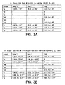
- Figure 4 sets forth various unbalanced faults (phase to ground and phase-to-phase to ground) and their associated phase angle difference (I ot -I 2t ) ranges which result from those faults, for the system shown in Figure 1.
- each ⁇ 60o sector in Figure 4 has two possible .
- Figure 5 illustrates the three ⁇ 60o angular sectors (24, 26, 28), centered, respectively, about the ideal center angles of 60o, 120o and -120o (300o), in which the faults of Figure 3 are located.
- the ⁇ 60o angle range about each center line accounts for distributed line capacitance, non-homogeneity and other system errors. Typically, however, the errors will not approach the 60o range limits.
- a phase angle difference in the first sector is the result of an A phase-to-ground or a BC phase-to-phase to ground fault.
- the BC phase-to-phase to ground fault possibility can, however, be eliminated if it is determined that the current I BC under those circumstances is not the largest phase-to-phase current (i.e . not the largest relative to I AB and I CA ).
- determining the angular difference between the total zero sequence current and the total negative sequence current when there is a fault, results in an angle sector value which in turn indicates that the fault is one of only two different types associated uniquely with that particular angular sector.
- the three sectors include all the phase to ground and phase-to-phase to ground fault-type possibilities.
- phase A, B and C three conventional single-phase protective elements (phase A, B and C) are included to provide input to a fault type logic circuit. These are shown as 87A, 87B and 87C signals.
- 87 is the industry designation for a differential protective element.
- the letter suffix after 87 indicates the monitored phase.
- single phase elements are identified but phase-to-phase elements could also be used.
- the fault type is a phase-to-phase fault, between the phases of the two picked-up phases, e.g. if phase A and phase B elements assert, the fault is an AB phase-to-phase fault. If all three phase elements pick up, the fault is three phase.
- the determination of a fault by the single phase elements is only reliable if the fault impedance is low.
- pick-up (or lack thereof) of the individual phase elements cannot be relied upon as an accurate determination of the existence of a fault, as the pick-up thresholds are often set higher than the fault current which may be present during higher impedance ground faults, so that an actual fault may not be recognized by the individual phase elements.
- the present system is directed toward solving that problem, among others, in identifying fault type.
- negative sequence and zero sequence angle determinations are used in addition to phase elements. If none of the phase elements pick up, and the angle determination circuitry is enabled, logic circuitry is enabled to identify the particular faulted phases. When the angle determination circuitry is enabled, the angle of both the zero sequence and negative sequence quantities is determined and the difference between the two is calculated. The difference angle is identified as being in one of the three sectors noted above ( Figure 5), and then the two possible are reduced to one by further processing, as discussed below. An output signal identifies the fault type. Hence, accurate fault type determination is made regardless of the magnitude of fault resistance, whether it be high or low, and also under a variety of power system conditions.
- phase elements 87A, 87B, 87C
- the outputs of the phase elements 30, 32 and 34 are applied as inputs to AND gates 40-45.
- AND gate 40 the output of phase A element 30 is applied to a non-inverting input, while the outputs of phase B and phase C elements 32 and 34 are applied to inverting inputs.
- AND gate 41 the output of B phase element 32 is applied to a non-inverting input, while the output of A phase and C phase elements 30 and 34 are applied to inverting inputs.
- the output of C phase element 34 is applied to an inverting input, while the outputs of A and B phase elements 30 and 32 are applied to non-inverting inputs.
- AND gate 40 will be high when the phase A element asserts (picks-up) and the phase B and C elements 32 and 34 do not assert.
- the output of AND gate 41 will be high when the phase B element 32 asserts, and the phase A and phase C elements 32 and 34 do not assert.
- the output of AND gate 42 will be high when C phase element 34 asserts, but A and B phase elements 30 and 32 do not assert. High outputs from AND gates 40, 41 and 42 indicate A, B and C phase single-line-to-ground faults, respectively.
- AND gate 43 the outputs of A phase and B phase elements 30 and 32 are applied to non-inverting inputs, while the output from C phase element 34 is applied to an inverting input.
- the output of AND gate 43 will be high when both phase elements 30 and 32 assert, but phase element 34 does not assert.
- a high output from AND gate 43 indicates either an AB phase-to-phase or an AB phase-to-phase to ground fault.
- AND gate 44 the outputs of B and C phase elements 32 and 34 are applied to non-inverting inputs, while the output from A phase element 30 is applied to an inverting input.
- the output of AND gate 44 will be high when elements 32 and 34 assert, while phase element 30 does not assert.
- This high input indicates either a BC phase-to-phase fault or a BC phase-to-phase to ground fault.
- AND gate 45 the outputs of A and C phase elements 30 and 34 are applied to non-inverting inputs, while the output of B phase element 32 is applied to an inverting input.
- the output of AND gate 45 will be high when phase elements 30 and 34 are asserted but phase element 32 is not asserted.
- a high output from AND gate 45 indicates a CA phase-to-phase fault or a CA phase-to-phase to ground fault.
- OR gates 50-55 The outputs of AND gates 40-45 are applied, respectively, to a series of output bit OR gates 50-55.
- phase elements (87LA, 87LB and 87LC) 30, 32 and 34 are also applied to an AND gate 66.
- the output of AND gate 66 is high when all three phase elements are asserted. A high output indicates a three-phase internal fault for the protected line.
- the output of AND gate 66 is applied at one input to OR gate 68.
- the other input to OR gate 68 is an input labeled FABC, which is a signal from the angle logic circuit ( Figure 7) which also is capable of determining a three-phase fault, as discussed below.
- the output of OR gate 68 is labeled FTABC.
- the FTABC signal is an output bit indicating a three-phase fault.
- a high output of FTABC may be used by the protective relay to block the operation of reclosing circuitry, since reclosing is usually ineffective for a three phase fault, and further can be used to illuminate the three-phase fault LED indicator on the front panel of the relay, as well as being used to indicate the fault type in the event summary report and event history, if desired.
- phase element outputs 30, 32 and 34 are also applied to an OR gate 70, the output of which is high when any of the phase elements 30, 32 and 34 pick-up. Otherwise, the output is low. As indicated above, the outputs of elements 30, 32 and 34 are reliable only when the fault resistance is low.
- OR gate 70 is applied to inverting inputs of AND gates 58-63. The actual inputs thus will be high only when none of the outputs 30, 32 34 of the phase elements are asserted. This could be due to non-fault conditions or there may be a fault with high fault resistance.
- signals FA, FB and FC from the angle logic circuitry of Figure 7 described below.
- OR gates 50, 51 and 52 will be high, respectively, for the conditions where there is phase A, B or C to ground faults. These are low resistance fault determinations. These outputs can be used to control tripping, the reclosing circuitry, illuminate the A phase, B phase or C phase LEDs on the relay front panel and indicate the in the event report summary and history, if desired.
- the other inputs to AND gates 61, 62 and 63, respectively, are the outputs of OR gates 74, 80 and 82.
- the inputs to OR gate 74 are a signal FAB from the angle logic circuit of Figure 7 discussed below and the output of a timer 76.
- Timer 76 is a time-delayed pickup, instantaneous dropout timer, which is initiated by an AB signal which is a signal from the angle logic circuit of Figure 7 discussed below.
- the FAB and the AB signals from the angle logic circuit are signals indicating that the angle circuit has determined a high resistance fault of AB phase-to-phase to ground or AB phase-to-phase.
- Either output produces a high output from OR gate 74 to AND gate 61 and then to OR gate 53 to produce an output bit which is used by the relay to control tripping, illuminate the A and B phase LEDs on the front panel and to indicate the fault type in the event summary and event history, if desired.
- BC phase-to-phase type faults including phase-to-phase to ground (OR gate 80 and timer 84) and CA phase-to-phase type faults (OR gate 82 and timer 86).
- OR gate 80 and timer 84 phase-to-phase to ground
- CA phase-to-phase type faults OR gate 82 and timer 86.
- the outputs of OR gates 80 and 82 are applied, respectively, to AND gates 62 and 63.
- the timers 76, 84 and 86 are all delayed in pickup (three counts or 3/16 of a power cycle) for security. This pick-up delay could be varied, depending on the desired security.
- the following description is directed toward the enablement of and the determination of the phase angle between the zero sequence and negative sequence values for follow-on determination of fault type for faults with high fault resistance.
- comparator 90 has an input of the ratio of the magnitude of the scaled (factor of 3) total zero sequence line current from all line terminals (3I o ) and the magnitude of the maximum phase-to-phase line current.
- the other input is 0.3 (30%).
- the output of comparator 90 is high.
- one input is the magnitude of the maximum phase-to-phase current and the other input is a threshold value of 4•I nom where I nom is the nominal secondary current rating for the relay (typically 1 or 5 amps).
- I nom is the nominal secondary current rating for the relay (typically 1 or 5 amps).
- Comparator 94 has at one input the ratio of the magnitude of the total zero sequence line current (I OT ) and the magnitude of the total negative sequence line current (I 2T ), and at the other input a threshold ratio value of 0.078. Hence, the output of comparator 94 will be high when the ratio is larger than 8%. This threshold value, however, can be varied.
- the outputs of comparators 90 and 92 are applied to an AND gate 96.
- the output of AND gate 96 is high when the threshold comparisons of comparators 90 and 92 are both satisfied.
- the output of comparator 92 is also applied to an inverting input of AND gate 98. Applied to the other input to AND gate 98 is the output of comparator 94.
- the output of AND gate 98 will be high when the output of comparator 94 is high, meaning that the threshold comparison of comparator 94 has been satisfied, and further, that the maximum phase-to-phase current magnitude is less than four times the nominal secondary current value, as determined by comparator 92.
- the output of AND gate 98 should thus be high for all faults having a current magnitude which satisfies the threshold values which are set high enough to ensure that the currents can be sensed by the relay.
- AND gate 96 The output of AND gate 96 is applied to an inverting input of AND gate 100.
- the output of comparator 92 is also applied to a non-inverting input of AND gate 100.
- a third input to AND gate 100 is from comparator 102.
- One input to comparator 102 is the ratio of the magnitude of the total zero sequence line current (I OT ) to the magnitude of the total positive sequence line current (I 1T ).
- the other input is a threshold value settable by the user. Typically, this setting value will be above the maximum current transformer imbalance value, which will range from 0-0.3 (0-30%), with a typical value of 0.03.
- AND gate 100 will thus be high for all high magnitude faults where the zero sequence current magnitude exceeds 3.0% of the maximum phase-to-phase current magnitude.
- This circuitry provides a safeguard against false outputs during high fault phase-to-phase faults, where one current transformer (CT) may saturate, which results in a false zero sequence current.
- CT current transformer
- the output of AND gate 100 is applied to an OR gate 104.
- the output of OR gate 104 is high when either (or both) of the outputs of AND gates 98 and 100 are high.
- the output from OR gate 104 is applied as one input to AND gate 106, the output of which enables the difference angle determination circuit 136.
- a second input to AND gate 106 is from comparator 108.
- One input to comparator 108 is the ratio of the total negative sequence line current (I 2T ) and the total positive sequence line current (I 1T ).
- the other input is a threshold ratio value of 0.02.
- the output of comparator 108 will be high for all unbalanced faults. For three-phase faults or normal load, the output of this comparator will block the enabling of the angle logic circuit, as this ratio threshold of comparator 108 should not be satisfied for those conditions.
- a third input to AND gate 106 is from OR gate 110.
- the inputs to OR gate 110 are the outputs from negative sequence current detectors for both local and remote negative sequence current. These are shown with industry designations 50L2 (local) and 50R2 (remote).
- a high output of OR gate 110 requires that at least one terminal have sufficient negative sequence current to be sensed by the relay.
- a fourth input to AND gate 106 is a signal indicating whether or not there is a three-pole (circuit breaker) open. If there is a three-pole open on the circuit breaker, a high signal will be applied to a non-inverting input of AND gate 106. This will block a high output from AND gate 106 and hence will block the enabling of the difference angle determining circuit.
- OR gate 112 The last input to AND gate 106 is from OR gate 112.
- a high output of OR gate 112 indicates that the zero sequence currents at one or more terminals are of sufficient magnitude for the angle of the zero sequence current to be relied upon.
- the output of OR gate 112 is determined as follows.
- a comparator 120 has one input which is the magnitude of the scaled total zero local sequence current from all terminals (3•I OL ); the other input is the scaled total local positive sequence current (3•I 1L ) multiplied by a setting factor "a" determined by the user. Typically, this setting factor will be 0.02, with a possible range of 0-0.30. Comparator 120 will be high for phase-to-ground faults and phase-to-phase to ground faults but will be low for normal load, phase-to-phase and three-phase faults.
- Comparator 122 compares the total local zero sequence current against a threshold value of 0.25 amps, which is typically 5% of I nom for a 5 amp nominal relay. The purpose of comparator 122 is to ensure that there is sufficient zero sequence current for a reliable angle.
- the outputs of comparators 120 and 122 are applied as inputs to an AND gate 124, the output of which is high when the outputs of comparators 120 and 122 are high, indicating that the stated thresholds involving zero sequence and positive sequence current ratios have been satisfied.
- Comparators 128 and 130 and AND gate 134 provide similar functions for the total remote terminal zero sequence and positive sequence currents.
- the outputs of AND gates 124 and 132 are then applied to OR gate 112, the output of which, as indicated, is the fifth input to AND gate 106.
- a high output of OR gate 112 requires that either or both outputs of AND gates 124 and 134 be high.
- a high output from AND gate 106 indicates that all of the threshold requirements for operation of the angle determination circuitry have been satisfied, specifically that the outputs of OR gates 108 and 110 are both high, as well as the output of OR gate 104, that there is not a three-pole open in the circuit breaker, and finally that OR gate 112 is high.
- These threshold security determinations basically confirm that the angle to be determined can be relied upon.
- the output of AND gate 106 is an FTSE signal (an output bit indicating that the fault logic has been enabled), which serves as an enable signal applied to difference angle determination circuit 136.
- difference angle determination circuit 136 the resulting angle value is the angular difference between the total zero sequence current and the total negative sequence current.
- the angle from circuit 136 will always be within one of the three angle sectors shown in Figure 5. These three sectors again are: 0o ⁇ 60o, 120o ⁇ 60o and -120o (240o) ⁇ 60o.
- the outputs of the three sector block 138 are applied to AND gates 140, 141 and 142, along with the enable signal from AND gate 106.
- the outputs of AND gates 140-142 are applied to timers 144, 145 and 146.
- timer 144 The output of timer 144 is an FSA' signal, indicating that the difference angle is within the first sector of 0o ⁇ 60o; the output from timer from 145 is an FSB' signal, indicating that the angle is within the second sector, and the third signal FSC' from timer 146 indicates that the angle is within the third sector.
- the FSA', FSB' and FSC' signals discussed above are applied to the supplemental (angle) logic circuit of Figure 7.
- the logic circuit of Figure 7 does not operate if any of the individual phase elements (87LA, 87LB, 87LC) assert, which indicates the presence of a low resistance fault, for which the circuit of Figure 7 is not necessary to provide fault identification.
- the circuit of Figure 7 is a processing routine which continuously examines the outputs of timers 144, 145 and 146. In block 150, a determination is made as to whether or not the FSA' bit has been asserted.
- the fault type is an A phase to ground fault or a BC phase-to-phase to ground fault. If the FSA' bit has not been asserted, then a determination is made as to whether or not the FSB' bit has been asserted, as shown in block 152. If this bit has been asserted, then the fault is either a B phase to ground fault or a CA phase-to-phase to ground fault. If FSB' has not asserted, then the FSC' bit is checked, at block 154, to determine whether that relay bit has been asserted. If that bit has been asserted, the fault is either a C phase-to-ground or an AB phase-to-phase to ground fault.
- the next check is to determine the fault type for unbalanced faults which do not involve ground, i.e . AB, BC and CA (block 156). If this fault detection variable is picked up, then the next step is to decipher whether or not the variable is picked up due to errant negative-sequence current. If the detection variable block does not assert, then the routine proceeds to the end.
- the ratio of the magnitude of the total negative sequence current (I 2T ) to the magnitude of the total positive sequence current (I 1T ) is checked against a threshold of 20% (block 158). If the ratio is less than 20%, then the fault is determined to be three-phase and the logic asserts an FABC output fault-type indication, which is applied back to the circuit of Figure 6, as an output to OR gate 68.
- the output of OR gate 68 sets an output bit indicative of a three-phase fault.
- the fault-type is identified by determining the maximum phase-to-phase current magnitude, either AB, BC or CA (depending on which phase-to-phase current magnitude is the greatest at that point).
- the ratio check of block 158 must be true for at least 3/16 of a cycle for the fault type to be asserted.
- the 3/16 of a cycle delay is provided by timers 76, 84 or 86 ( Figure 6), and can be varied. This is explained above relative to the output bits ultimately asserted at the output of OR gates 53, 54 or 55. These outputs again signify the fault type.
- the fault type could be either an A phase to ground or a B phase-to-C phase to ground fault.
- I BC will have the least total phase current among the three possible phase-phase currents, because the B-C phase pair is not involved in an AG fault.
- a comparison is thus made at block 160 to determine whether I BC has the maximum phase-to-phase current. If I BC is the maximum phase-to-phase current, the fault type must be a BC phase-to-phase to ground fault. That fault type is then set at block 162 and an FBC bit is set for application to OR gate 80 in Figure 6. The output for the fault type is through OR gate 54 for the BC fault type.
- a block 172 which first determines whether the total A phase current is the maximum current. If it is YES, the fault type is indicated to be an A phase-to-ground fault and an FA bit is set, at block 174, for application back to Figure 6, specifically AND gate 58, and ultimately output OR gate 50. If the total B phase current is maximum (block 176), then an FB bit is set at block 178 and applied back to Figure 6 to AND gate 59 and output OR gate 51. If neither A phase or B phase current is maximum, then the FC bit is set, at block 180, which is applied back to Figure 6 to AND gate 60 and then output gate 52. In operation, blocks 172 and 176 are not necessary but included for additional protection and ultimate simplicity of operation.
- the output bits from blocks 162, 166, 170, 174, 178 and 180 are used by the logic circuit of Figure 6 to indicate fault types which involve high resistance faults, from output OR gates 50-55. Those bit outputs are used to control tripping, reclosers, panel LEDs and event reports, as well as fault processing circuitry.
- the conventional 87A, 87B and 87C elements are used to provide the bit outputs through OR gates 50-55 when low resistance faults are involved.
- phase elements 87LA, 87LB and 87LC could in effect be replaced by sequence quantity element(s) (e.g. a positive sequence element).
- sequence quantity element(s) e.g. a positive sequence element.
- the FTAG, FTBG and FTCG outputs in Figure 6 are supplied by the FA, FB and FC signals from Figure 7 and the FTAB, FTBC and FTCA outputs in Figure 6 are provided directly from OR gates 74, 80 and 82, which are responsive to the inputs shown in Figure 6.
- AND gates 40-45 and 58-63 and OR gates 50-55 are eliminated in this arrangement.
- the process routine of Figure 7 is started by an indication of the existence of a fault condition by action of a sequence element.
- the remaining circuitry of Figures 6 and 7 determines the fault type as explained above.
Landscapes
- Engineering & Computer Science (AREA)
- Power Engineering (AREA)
- Physics & Mathematics (AREA)
- Electromagnetism (AREA)
- Emergency Protection Circuit Devices (AREA)
- Testing Of Short-Circuits, Discontinuities, Leakage, Or Incorrect Line Connections (AREA)
Abstract
Description
Claims (21)
- A system for fault type identification in an electric power system, using three-phase current information on the power line, comprising:a first circuit means responsive to protective elements which recognize the presence of single line-to-ground (SLG) faults for phases A, B and C on a power transmission line, the first circuit means including a portion thereof for recognizing and asserting output indications of single line-to-ground faults, faults involving two phases and three-phase faults, in response to the occurrence of different combinations of outputs from the protective elements;a calculation circuit, responsive to an enable signal generated upon the determination of the existence of selected threshold current conditions on the line, for determining the angular difference between the total zero sequence current and the total negative sequence current for the three-phase current on the power line, for identifying high resistance faults, wherein the angular difference is in one of three pre-selected angular difference sectors, wherein an angle difference in the first sector indicates an A phase to ground fault or a BC phase-to-phase to ground- fault, wherein an angle difference in the second sector indicates a B phase to ground fault or a CA phase-to-phase to ground fault, and where an angle difference in the third sector indicates a C phase to ground fault or an AB phase-to-phase to ground fault angle differences in each of the three sectors being indicated by sector signals; andprocessing means for determining which of the two possible fault types indicated by the determined angular difference is the actual fault type and for providing a signal indication of said actual fault type.
- The system of claim 1, wherein the first sector covers an angle difference range of ±60º about a 0º center, wherein the second sector covers an angle difference range of ±60º about a 120º center, and wherein the third sector covers an angle difference of ±60º about a -120º center.
- The system of claim 1, wherein the processing means asserts a three-phase fault and provides an output indication thereof in the event that none of the sector signals are present and the total negative sequence current is less than a selected fraction of the total positive sequence current.
- The system of claim 3, wherein the selected fraction is 1/5.
- The system of claim 1, wherein a three-phase fault is asserted by said first circuit means when all three protective elements assert, indicating a fault on all three phases.
- The system of claim 1, including means for transmitting the signal indications of fault type produced by the processing means to the first circuit means which is responsive thereto and to the protective elements to produce said output indications of fault type.
- The system of claim 2 wherein if a first sector signal is asserted and the BC phase-to-phase current (IBC) is the maximum phase-to-phase current, the fault type is asserted as a BC phase-to-phase to ground fault, otherwise the fault is asserted as an A phase-to-ground fault; wherein if a third sector signal is asserted and the CA phase-to-phase current (ICA) is the maximum phase-to-phase current, the fault type is asserted as a CA phase-to-phase to ground fault, otherwise the fault is asserted as a B phase-to-ground fault; and wherein if the second sector signal is asserted and the AB phase current (IAB) is the maximum phase-to-phase current, the fault type is asserted as an AB phase-to-phase to ground fault, otherwise, a C phase-to-ground fault is asserted.
- The system of claim 1, including a first timer means for delaying the assertion of the sector signals.
- The system of claim 8, wherein the delay is 3/16 of a power system cycle.
- The system of claim 1, including an enable circuit for the calculation circuit, the enable circuit including a plurality of threshold determinations which must be satisfied prior to the calculation circuit being enabled.
- The system of claim 1, wherein the processing means asserts a phase-to-phase fault type indication (AB, BC, CA) for the maximum phase-to-phase current value when none of the sector signals are asserted and the total negative sequence current is larger than a selected fraction of the total positive sequence current.
- The system of claim 11, including second timers for delaying said assertion of said phase-to-phase faults identified by the processing means, the delay being 3/16 of a power system cycle.
- The system of claim 10, wherein one threshold is the presence of a selected minimum amount of negative sequence current.
- The system of claim 10, wherein one threshold is a selected minimum ratio of zero sequence current to negative sequence current, in combination with a selected minimum value of zero sequence current.
- The system of claim 10, wherein one threshold is a selected minimum ratio of total negative sequence current to total positive sequence current.
- The system of claim 15, wherein the minimum ratio is 0.02.
- The system of claim 10, wherein one threshold is the combination of: 1) the ratio of total zero sequence current to total positive sequence current is greater than 0.03; (2) the maximum phase-to-phase current is greater than four times the nominal secondary current; and (3) the ratio of the total zero sequence current over the maximum phase-to-phase current is less than 0.3.
- The system of claim 17, wherein another threshold includes: (1) the ratio of the total zero sequence current to the total negative sequence current is greater than 0.078 and (2) the maximum phase-to-phase current is less than four times the nominal secondary current.
- A system for fault type identification useful in a protective relay for an electric power system, using three phase current information from the power line, comprising:a first circuit means responsive to protective elements which recognize the presence of single phase to ground faults for phases A, B and C on the power line, the first circuit means including a portion thereof for recognizing and then asserting output indications of single phase to ground faults; faults involving two phases, and three phase faults, in response to the currents of different combinations of outputs from the protective elements;a calculation circuit, responsive to an enable signal generated upon the determination of the existence of selected threshold current conditions on the line, for determining the angular difference between the total zero sequence current and the total negative sequence for the three phase current on the power line, for identifying high resistance faults, wherein the angular difference is in one of three angular difference sectors, wherein an angular difference in a first sector indicates first and second possible fault types, wherein an angle difference in the second sector indicates third and fourth possible fault types, and wherein an angle difference in the third sector indicates fifth and sixth possible fault types; andprocessing means for determining which of the two possible fault types in each sector is the actual fault type and providing a signal indication of said actual fault type.
- A system for fault type identification useful in a protective relay for an electric power system, using three phase current information from the power line, comprising:a calculation circuit, responsive to an enable signal generated upon the determination of the existence of selected threshold current conditions on the line, for determining the angular difference between the total zero sequence current and the total negative sequence for the three phase current on the power line, wherein the angular difference is in one of three angular difference sectors, wherein an angular difference in a first sector indicates first and second possible fault types , wherein an angle difference in the second sector indicates third and fourth possible fault types, and wherein an angle difference in the third sector indicates fifth and sixth possible fault types; andprocessing means for determining which of the two possible fault types in each sector is the actual fault type and providing a signal indication of said actual fault type, the processing means being responsive to a protective element recognizing the existence of a fault condition, the processing means having the capability of identifying phase-to-phase fault types, which are not part of the first through sixth fault types and which do not involve ground.
- The system of claim 20, wherein the first and second fault types are A phase to ground and BC phase-to-phase to ground, wherein the third and fourth possible fault types are B phase to ground and CA phase-to-phase to ground and wherein the fifth and sixth fault types are C phase to ground and AB phase-to-phase to ground.
Applications Claiming Priority (2)
| Application Number | Priority Date | Filing Date | Title |
|---|---|---|---|
| US09/693,607 US6525543B1 (en) | 2000-10-20 | 2000-10-20 | Fault type selection system for identifying faults in an electric power system |
| US693607 | 2000-10-20 |
Publications (2)
| Publication Number | Publication Date |
|---|---|
| EP1207610A2 true EP1207610A2 (en) | 2002-05-22 |
| EP1207610A3 EP1207610A3 (en) | 2005-12-14 |
Family
ID=24785364
Family Applications (1)
| Application Number | Title | Priority Date | Filing Date |
|---|---|---|---|
| EP01308792A Withdrawn EP1207610A3 (en) | 2000-10-20 | 2001-10-16 | Fault type selection system for identifying faults in an electric power system |
Country Status (11)
| Country | Link |
|---|---|
| US (1) | US6525543B1 (en) |
| EP (1) | EP1207610A3 (en) |
| KR (1) | KR100822988B1 (en) |
| CN (1) | CN1355585A (en) |
| AU (1) | AU776631B2 (en) |
| BR (1) | BRPI0104617B1 (en) |
| CA (1) | CA2359500C (en) |
| HK (1) | HK1045410A1 (en) |
| MX (1) | MXPA01010502A (en) |
| NZ (1) | NZ514894A (en) |
| ZA (1) | ZA200108588B (en) |
Cited By (6)
| Publication number | Priority date | Publication date | Assignee | Title |
|---|---|---|---|---|
| EP1696531A3 (en) * | 2005-02-22 | 2006-11-02 | AREVA T&D UK Ltd. | A method and an apparatus for supervising the operation of current transformers of a protection relay |
| WO2011060814A1 (en) * | 2009-11-17 | 2011-05-26 | Areva T&D Uk Limited | Fuzzy interference relay and method for current differential protection of a transmission line |
| CN103592537A (en) * | 2013-10-31 | 2014-02-19 | 李景禄 | Electric line fault alternating-current impedance fast tracking and judging method |
| WO2016091334A1 (en) * | 2014-12-12 | 2016-06-16 | Siemens Aktiengesellschaft | Method and protection device for generating an error signal indicating an error type of an error in a multi-phase electrical energy supply network |
| WO2016193529A1 (en) * | 2015-06-03 | 2016-12-08 | Jyväskylän Energia Oy | Method for earth fault protection for a three-phase electrical network |
| CN116609615A (en) * | 2023-05-31 | 2023-08-18 | 国网陕西省电力有限公司电力科学研究院 | High-resistance fault detection method, device and equipment based on arc current change trend |
Families Citing this family (81)
| Publication number | Priority date | Publication date | Assignee | Title |
|---|---|---|---|---|
| US6525543B1 (en) * | 2000-10-20 | 2003-02-25 | Schweitzer Engineering Laboratories | Fault type selection system for identifying faults in an electric power system |
| DE10139318C2 (en) * | 2001-08-09 | 2003-06-18 | Siemens Ag | Method for error detection in an electrical radiation network, an application of the method and an arrangement for error detection in an electrical radiation network |
| US6922656B2 (en) * | 2002-04-18 | 2005-07-26 | Caterpillar Inc | Method and system of identifying a problem prone part |
| US6839210B2 (en) * | 2002-10-25 | 2005-01-04 | Schweitzer Engineering Laboratories, Inc. | Bus total overcurrent system for a protective relay |
| DE10251001B3 (en) * | 2002-10-30 | 2004-02-26 | Siemens Ag | Earth short-circuit fault signal provision method for multi-phase transmission line monitoring with detection of phase current transducer saturation |
| CN100346548C (en) * | 2004-02-19 | 2007-10-31 | 烟台东方电子信息产业股份有限公司 | Discriminiting element for developmental fault of high-voltage transmission line of power system |
| US7400150B2 (en) * | 2004-08-05 | 2008-07-15 | Cannon Technologies, Inc. | Remote fault monitoring in power lines |
| US7355412B1 (en) | 2004-08-05 | 2008-04-08 | Cannon Technologies, Inc. | Remote fault monitoring system |
| US20060152866A1 (en) * | 2005-01-13 | 2006-07-13 | Gabriel Benmouyal | System for maintaining fault-type selection during an out-of-step condition |
| US7660088B2 (en) * | 2005-09-07 | 2010-02-09 | Schweitzer Engineering Laboratories, Inc. | System, apparatus and method for compensating the sensitivity of a sequence element in a line current differential relay in a power system |
| EP2122795A1 (en) * | 2007-02-20 | 2009-11-25 | ABB Technology AG | Device and method for detecting faulted phases in a multi-phase electrical network |
| CA2585820A1 (en) * | 2007-04-18 | 2008-10-18 | Hydro-Quebec | Localizing faults on an electrical network using distributed voltage measurement |
| EP2160809A1 (en) * | 2007-06-27 | 2010-03-10 | Siemens Aktiengesellschaft | Method for increasing the sensitivity of a differential protection system |
| US7969155B2 (en) * | 2007-07-03 | 2011-06-28 | Thomas & Betts International, Inc. | Directional fault current indicator |
| US8405944B2 (en) * | 2007-10-09 | 2013-03-26 | Schweitzer Engineering Laboratories Inc | Distributed bus differential protection using time-stamped data |
| US8031447B2 (en) * | 2007-10-09 | 2011-10-04 | Schweitzer Engineering Laboratories, Inc. | Transformer through-fault current monitor |
| EP2319151A4 (en) * | 2008-08-29 | 2013-12-25 | Abb Research Ltd | METHOD AND DEVICE FOR ERROR IDENTIFICATION IN AN ENERGY TRANSMISSION LINE |
| US9614389B2 (en) * | 2009-04-14 | 2017-04-04 | Ford Global Technologies, Llc | Method and system for controlling current flow through a power distribution circuit |
| WO2010148570A1 (en) * | 2009-06-26 | 2010-12-29 | Abb Research Ltd. | Method for identifying type of fault on power line |
| US8575941B2 (en) * | 2009-09-08 | 2013-11-05 | Schweitzer Engineering Laboratories Inc | Apparatus and method for identifying a faulted phase in a shunt capacitor bank |
| US9132741B2 (en) * | 2009-10-08 | 2015-09-15 | Ford Global Technologies, Llc | Method and system for controlling current flow through a power distribution circuit |
| CN101789583B (en) * | 2010-01-15 | 2012-08-29 | 许昌开普电器检测研究院 | Real-time digital emulation automatic test method |
| US8797018B2 (en) * | 2010-01-22 | 2014-08-05 | Schweitzer Engineering Laboratories, Inc. | Apparatus and method for identifying the phase and terminal for power system devices |
| US8855951B2 (en) * | 2010-04-13 | 2014-10-07 | Ford Global Technologies, Llc | Power distribution circuit diagnostic system and method |
| US8525522B2 (en) * | 2010-04-21 | 2013-09-03 | Schweitzer Engineering Laboratories Inc | Fault location in electric power delivery systems |
| US8558551B2 (en) | 2010-04-21 | 2013-10-15 | Schweitzer Engineering Laboratories Inc | Fault location in electric power delivery systems |
| US8717725B2 (en) | 2010-12-02 | 2014-05-06 | Schweitzer Engineering Laboratories Inc | Dual-comparator restricted earth fault protection |
| US9435835B2 (en) | 2010-12-27 | 2016-09-06 | Schweitzer Engineering Laboratories, Inc. | Validation of electric power system monitoring systems |
| CN102279345A (en) * | 2011-03-09 | 2011-12-14 | 天津大学 | Comprehensive phase selecting method for common-tower parallel transmission lines |
| CN102332707B (en) * | 2011-06-08 | 2014-04-16 | 高政 | Earth fault signal measuring method and protective device for ungrounded system |
| CN102288871B (en) * | 2011-06-23 | 2014-06-04 | 陕西电力科学研究院 | Method for judging and processing large-span interphase short circuit grounding fault |
| US8867181B2 (en) * | 2011-09-23 | 2014-10-21 | GM Global Technology Operations LLC | Protection of motor drive systems from current sensor faults |
| US8791704B2 (en) * | 2011-10-11 | 2014-07-29 | Schweitzer Engineering Laboratories Inc. | Fault-type identification for electric power delivery systems |
| CN103852688B (en) * | 2012-11-30 | 2016-11-16 | 施耐德电器工业公司 | For the method and apparatus determining the position of earth fault |
| CN103344875B (en) * | 2013-07-02 | 2015-07-22 | 福州大学 | Classification line selection method for single-phase earth fault of resonance earthing system |
| DE102013114729B4 (en) * | 2013-12-20 | 2021-09-30 | Sma Solar Technology Ag | Inverter and method for detecting a phase failure in an energy supply network |
| CN103728538B (en) * | 2013-12-30 | 2016-09-21 | 国家电网公司 | A kind of ground fault line selecting method of small current neutral grounding system |
| US20160054421A1 (en) * | 2014-08-19 | 2016-02-25 | Dipl.-Ing. H. Horstmann Gmbh | Method for calibrating a short circuit indicator with direction detection and short circuit indicator to use such a method |
| CN104391229B (en) * | 2014-12-04 | 2017-02-22 | 山东大学 | Transmission line fault fast phase selection method based on S conversion |
| CN104502802A (en) * | 2014-12-24 | 2015-04-08 | 国家电网公司 | Method and system for recognizing lightning strike fault and lightning strike fault type of power transmission line |
| CN104502804B (en) * | 2014-12-24 | 2017-07-11 | 国家电网公司 | The recognition methods of transmission line lightning stroke failure and lightning fault type and system |
| CN104614638A (en) * | 2014-12-24 | 2015-05-13 | 国家电网公司 | Grounding line selection method for small current system |
| US9941684B2 (en) * | 2015-05-12 | 2018-04-10 | Schweitzer Engineering Laboratories, Inc. | Phase and ground protection using tilt-limited adaptive quadrilateral characteristic |
| CN105589012B (en) * | 2015-07-27 | 2018-08-03 | 中国计量学院 | Interconnection type micro-capacitance sensor unbalanced fault regional detection device and diagnostic method |
| CN105334748B (en) * | 2015-10-16 | 2018-03-02 | 国网重庆市电力公司电力科学研究院 | A kind of conversion of power system multiple faults type and temporal scalable simulator based on RTDS |
| CN105510731B (en) * | 2015-11-26 | 2018-04-20 | 国网辽宁省电力有限公司大连供电公司 | Power transformer medium voltage side power grid parallel resonance detects alarm method and system |
| CN105911883B (en) * | 2016-04-29 | 2018-09-18 | 许昌开普检测研究院股份有限公司 | The failure point control system of electric power real time data display |
| US10381823B2 (en) * | 2016-05-20 | 2019-08-13 | Infineon Technologies Ag | Device with power switch |
| US20180145497A1 (en) * | 2016-11-23 | 2018-05-24 | Schneider Electric USA, Inc. | Method to utilize multiple configuration software for df/cafi breakers |
| US10495680B2 (en) | 2017-06-14 | 2019-12-03 | Schweitzer Engineering Laboratories, Inc. | Systems and methods for detecting current transformer ultrasaturation to enhance relay security and dependability |
| CN109038513B (en) * | 2017-08-21 | 2019-09-10 | 李景禄 | A kind of intelligent processing method of the broken string ground connection for failure phase transfer earthing or grounding means |
| EP3729581A1 (en) | 2017-12-20 | 2020-10-28 | ABB Power Grids Switzerland AG | Zero sequence current based differential protection of a transmission line |
| WO2019120517A1 (en) | 2017-12-20 | 2019-06-27 | Abb Schweiz Ag | Phase selection using multi-terminal measurements of a transmission line |
| CN108459233B (en) * | 2018-03-27 | 2024-01-19 | 深圳供电局有限公司 | Equivalent circuit of main transformer high-voltage two-phase disconnection fault and identification method |
| US10775448B2 (en) | 2018-06-18 | 2020-09-15 | Schweitzer Engineering Laboratories, Inc. | Automatic phase identification for electric power delivery lines |
| CN109188206A (en) * | 2018-09-11 | 2019-01-11 | 国网江苏省电力有限公司泰州供电分公司 | A kind of guard method with branched line based on petal type power grid |
| US10677834B2 (en) | 2018-09-14 | 2020-06-09 | Schweitzer Engineering Laboratories, Inc. | Distance protection of electric power delivery systems using time domain and frequency domain |
| US10641815B2 (en) | 2018-09-27 | 2020-05-05 | Schweitzer Engineering Laboratories, Inc. | Secure distance protection of electric power delivery systems under transient conditions |
| US10859639B2 (en) | 2018-10-02 | 2020-12-08 | Schweitzer Engineering Laboratories, Inc. | Fault-type identification in an electric power delivery system using composite signals |
| CN112054487B (en) * | 2019-06-05 | 2022-05-03 | 李景禄 | Single-phase earth fault judgment and processing method for direct-distribution new energy power plant |
| US11567109B2 (en) | 2019-10-11 | 2023-01-31 | Schweitzer Engineering Laboratories, Inc. | Capacitor bank control using wireless electrical measurement sensors away from capacitor bank |
| US11177645B2 (en) | 2019-11-22 | 2021-11-16 | Schweitzer Engineering Laboratories, Inc. | Systems and methods for improving restricted earth fault protection |
| CN111060739B (en) * | 2020-02-14 | 2021-10-12 | 东方电子股份有限公司 | Fault type identification method based on differential current and fault characteristic quantity |
| US11159010B1 (en) * | 2020-05-19 | 2021-10-26 | Russell W. Patterson | Apparatus and method for producing negative sequence current |
| EP3961836B1 (en) * | 2020-09-01 | 2026-02-25 | Hitachi Energy Ltd | Determining of a power line fault |
| US11592498B2 (en) | 2020-10-02 | 2023-02-28 | Schweitzer Engineering Laboratories, Inc. | Multi-phase fault identification in capacitor banks |
| CN112330615B (en) * | 2020-10-27 | 2022-11-29 | 华能新能源股份有限公司河北分公司 | Method and system for monitoring state of high-strength bolt of rotating part |
| US11411390B2 (en) | 2020-12-31 | 2022-08-09 | Schweitzer Engineering Laboratories, Inc. | Secure and dependable restricted earth fault protection for electric power generators and transformers |
| US11735907B2 (en) | 2021-02-03 | 2023-08-22 | Schweitzer Engineering Laboratories, Inc. | Traveling wave overcurrent protection for electric power delivery systems |
| US11808824B2 (en) | 2021-03-17 | 2023-11-07 | Schweitzer Engineering Laboratories, Inc. | Systems and methods to identify open phases of a capacitor bank |
| US12313701B2 (en) | 2021-03-17 | 2025-05-27 | Schweitzer Engineering Laboratories, Inc. | Capacitor bank fault detection and identification |
| AU2021212036B1 (en) * | 2021-05-06 | 2021-10-21 | Russell Patterson | Apparatus and method for producing negative sequence current |
| CN113358979B (en) * | 2021-07-07 | 2023-10-20 | 长沙理工大学 | A phase selection method and phase selection device for single-phase disconnection fault in distribution network |
| US12244135B2 (en) | 2021-12-01 | 2025-03-04 | Schweitzer Engineering Laboratories, Inc. | Differential protection using instrument transformer signal transducers |
| CN114613221A (en) * | 2022-03-11 | 2022-06-10 | 王波 | Training and checking device for intelligent setting and recovery of electrical control fault |
| CN115021206B (en) * | 2022-06-17 | 2025-03-18 | 广东电网有限责任公司广州供电局 | High-resistance grounding fault longitudinal protection method and device based on double-terminal zero-sequence current ratio |
| US12308635B2 (en) | 2022-08-01 | 2025-05-20 | Schweitzer Engineering Laboratories, Inc. | Unbalance protection for shunt capacitor banks |
| US12287362B2 (en) | 2022-11-07 | 2025-04-29 | Ge Infrastructure Technology Llc | Systems and methods for identifying grid fault type and faulted phase |
| US12418168B2 (en) | 2023-01-25 | 2025-09-16 | Schweitzer Engineering Laboratories, Inc. | High-impedance differential protection using a diversity of signals |
| US12603490B2 (en) | 2023-11-01 | 2026-04-14 | Schweitzer Engineering Laboratories, Inc. | Protective device with multi-channel line current differential protection |
| CN119165401B (en) * | 2024-09-30 | 2025-12-16 | 广东电网有限责任公司 | Methods, devices, electronic equipment and storage media for detecting high-resistance grounding faults in power distribution networks |
Family Cites Families (9)
| Publication number | Priority date | Publication date | Assignee | Title |
|---|---|---|---|---|
| FR1597420A (en) * | 1968-07-05 | 1970-06-29 | ||
| EP0207610A1 (en) * | 1985-06-14 | 1987-01-07 | W.R. Grace & Co. | Taped bag chain with cassette |
| US4704653A (en) * | 1985-12-10 | 1987-11-03 | Westinghouse Electric Corp. | Transformer differential relay with speed-up apparatus |
| US4795983A (en) * | 1988-03-07 | 1989-01-03 | Westinghouse Electric Corp. | Method and apparatus for identifying a faulted phase |
| US5179495A (en) * | 1990-08-02 | 1993-01-12 | Furnas Electric Company | Solid state overload relay |
| CA2108442C (en) * | 1992-10-16 | 2000-04-25 | Jeffrey B. Roberts | Fault identification system for use in protective relays for power transmission lines |
| US5796258A (en) * | 1997-01-30 | 1998-08-18 | Abb Power T&D Company, Inc. | Adaptive quadrilateral characteristic distance relay |
| US6256592B1 (en) * | 1999-02-24 | 2001-07-03 | Schweitzer Engineering Laboratories, Inc. | Multi-ended fault location system |
| US6525543B1 (en) * | 2000-10-20 | 2003-02-25 | Schweitzer Engineering Laboratories | Fault type selection system for identifying faults in an electric power system |
-
2000
- 2000-10-20 US US09/693,607 patent/US6525543B1/en not_active Expired - Lifetime
-
2001
- 2001-10-16 AU AU79454/01A patent/AU776631B2/en not_active Ceased
- 2001-10-16 EP EP01308792A patent/EP1207610A3/en not_active Withdrawn
- 2001-10-17 MX MXPA01010502A patent/MXPA01010502A/en active IP Right Grant
- 2001-10-17 NZ NZ514894A patent/NZ514894A/en not_active IP Right Cessation
- 2001-10-18 BR BRPI0104617-9A patent/BRPI0104617B1/en not_active IP Right Cessation
- 2001-10-18 ZA ZA200108588A patent/ZA200108588B/en unknown
- 2001-10-19 KR KR1020010064800A patent/KR100822988B1/en not_active Expired - Fee Related
- 2001-10-19 CA CA2359500A patent/CA2359500C/en not_active Expired - Fee Related
- 2001-10-22 CN CN01141580A patent/CN1355585A/en active Pending
-
2002
- 2002-09-20 HK HK02106859.5A patent/HK1045410A1/en unknown
Cited By (8)
| Publication number | Priority date | Publication date | Assignee | Title |
|---|---|---|---|---|
| EP1696531A3 (en) * | 2005-02-22 | 2006-11-02 | AREVA T&D UK Ltd. | A method and an apparatus for supervising the operation of current transformers of a protection relay |
| WO2011060814A1 (en) * | 2009-11-17 | 2011-05-26 | Areva T&D Uk Limited | Fuzzy interference relay and method for current differential protection of a transmission line |
| CN103592537A (en) * | 2013-10-31 | 2014-02-19 | 李景禄 | Electric line fault alternating-current impedance fast tracking and judging method |
| CN103592537B (en) * | 2013-10-31 | 2016-03-02 | 李景禄 | Electric line fault AC impedance follows the tracks of determining method fast |
| WO2016091334A1 (en) * | 2014-12-12 | 2016-06-16 | Siemens Aktiengesellschaft | Method and protection device for generating an error signal indicating an error type of an error in a multi-phase electrical energy supply network |
| US11175329B2 (en) | 2014-12-12 | 2021-11-16 | Siemens Aktiengesellschaft | Method and protection device for generating an error signal indicating an error type of an error in a multi-phase electrical energy supply network |
| WO2016193529A1 (en) * | 2015-06-03 | 2016-12-08 | Jyväskylän Energia Oy | Method for earth fault protection for a three-phase electrical network |
| CN116609615A (en) * | 2023-05-31 | 2023-08-18 | 国网陕西省电力有限公司电力科学研究院 | High-resistance fault detection method, device and equipment based on arc current change trend |
Also Published As
| Publication number | Publication date |
|---|---|
| MXPA01010502A (en) | 2003-05-19 |
| CA2359500A1 (en) | 2002-04-20 |
| EP1207610A3 (en) | 2005-12-14 |
| CA2359500C (en) | 2011-02-08 |
| US6525543B1 (en) | 2003-02-25 |
| NZ514894A (en) | 2003-04-29 |
| AU7945401A (en) | 2002-05-02 |
| AU776631B2 (en) | 2004-09-16 |
| BR0104617A (en) | 2002-12-10 |
| BRPI0104617B1 (en) | 2015-06-16 |
| KR100822988B1 (en) | 2008-04-16 |
| ZA200108588B (en) | 2002-08-08 |
| HK1045410A1 (en) | 2002-11-22 |
| CN1355585A (en) | 2002-06-26 |
| KR20020031078A (en) | 2002-04-26 |
Similar Documents
| Publication | Publication Date | Title |
|---|---|---|
| US6525543B1 (en) | Fault type selection system for identifying faults in an electric power system | |
| US5515227A (en) | Fault identification system for use in protective relays for power transmission lines | |
| US10859639B2 (en) | Fault-type identification in an electric power delivery system using composite signals | |
| CA2464323C (en) | Directional element to determine faults on ungrounded power systems | |
| US7196884B2 (en) | Apparatus and method for detecting the loss of a current transformer connection coupling a current differential relay to an element of a power system | |
| US6518767B1 (en) | Line differential protection system for a power transmission line | |
| US6785105B2 (en) | Ground fault detection system for ungrounded power systems | |
| US20020101229A1 (en) | Line differential protection system for a power transmission line | |
| CN103733458B (en) | The method of the distance protection of parallel transmission-line | |
| EP1940001A2 (en) | Relay device and corresponding method | |
| US5783946A (en) | Fault type classification algorithm | |
| US6914762B2 (en) | Protection of electrical power lines | |
| US11271389B2 (en) | Distance protection using supervised sequence currents and voltages for electric power delivery systems | |
| US20030123204A1 (en) | Protection of double circuit power lines | |
| US5808845A (en) | System for preventing sympathetic tripping in a power system | |
| JP2004080839A (en) | Ground fault directional relay and ground fault directional relay | |
| US20060152866A1 (en) | System for maintaining fault-type selection during an out-of-step condition | |
| EP3830920A2 (en) | A method and a device for supervision of a voltage transformer | |
| US8395871B2 (en) | Device and method for detecting faulted phases in a multi-phase electrical network | |
| Bo | Adaptive non-communication protection for power lines BO scheme 3-The accelerated operation approach | |
| US12166340B2 (en) | Method and system for detecting faults in a low voltage three-phase network | |
| US6101075A (en) | System for improving protective relay coordination with other protective elements in power system | |
| US11962140B2 (en) | Coordination of protective elements in an electric power system | |
| Rizvi et al. | Using symmetrical components for internal external fault discrimination in differential protection schemes | |
| JP2002139538A (en) | Base point terminal selection method for multiple-port fault point locating device |
Legal Events
| Date | Code | Title | Description |
|---|---|---|---|
| PUAI | Public reference made under article 153(3) epc to a published international application that has entered the european phase |
Free format text: ORIGINAL CODE: 0009012 |
|
| AX | Request for extension of the european patent |
Free format text: AL;LT;LV;MK;RO;SI |
|
| PUAL | Search report despatched |
Free format text: ORIGINAL CODE: 0009013 |
|
| AK | Designated contracting states |
Kind code of ref document: A3 Designated state(s): AT BE CH CY DE DK ES FI FR GB GR IE IT LI LU MC NL PT SE TR |
|
| AX | Request for extension of the european patent |
Extension state: AL LT LV MK RO SI |
|
| RIC1 | Information provided on ipc code assigned before grant |
Ipc: 7H 02H 3/34 B Ipc: 7H 02H 7/26 B Ipc: 7H 02H 3/40 A |
|
| 17P | Request for examination filed |
Effective date: 20060613 |
|
| AKX | Designation fees paid |
Designated state(s): AT BE CH CY DE DK ES FI FR GB GR IE IT LI LU MC NL PT SE TR |
|
| STAA | Information on the status of an ep patent application or granted ep patent |
Free format text: STATUS: THE APPLICATION IS DEEMED TO BE WITHDRAWN |
|
| 18D | Application deemed to be withdrawn |
Effective date: 20080503 |