EP1207458A2 - Data-storing device - Google Patents
Data-storing device Download PDFInfo
- Publication number
- EP1207458A2 EP1207458A2 EP01126866A EP01126866A EP1207458A2 EP 1207458 A2 EP1207458 A2 EP 1207458A2 EP 01126866 A EP01126866 A EP 01126866A EP 01126866 A EP01126866 A EP 01126866A EP 1207458 A2 EP1207458 A2 EP 1207458A2
- Authority
- EP
- European Patent Office
- Prior art keywords
- power
- data
- interface
- supplied
- coupled
- Prior art date
- Legal status (The legal status is an assumption and is not a legal conclusion. Google has not performed a legal analysis and makes no representation as to the accuracy of the status listed.)
- Withdrawn
Links
Images





Classifications
-
- G—PHYSICS
- G06—COMPUTING OR CALCULATING; COUNTING
- G06F—ELECTRIC DIGITAL DATA PROCESSING
- G06F1/00—Details not covered by groups G06F3/00 - G06F13/00 and G06F21/00
- G06F1/16—Constructional details or arrangements
- G06F1/18—Packaging or power distribution
-
- G—PHYSICS
- G06—COMPUTING OR CALCULATING; COUNTING
- G06F—ELECTRIC DIGITAL DATA PROCESSING
- G06F1/00—Details not covered by groups G06F3/00 - G06F13/00 and G06F21/00
- G06F1/26—Power supply means, e.g. regulation thereof
- G06F1/266—Arrangements to supply power to external peripherals either directly from the computer or under computer control, e.g. supply of power through the communication port, computer controlled power-strips
-
- G—PHYSICS
- G06—COMPUTING OR CALCULATING; COUNTING
- G06F—ELECTRIC DIGITAL DATA PROCESSING
- G06F13/00—Interconnection of, or transfer of information or other signals between, memories, input/output devices or central processing units
- G06F13/38—Information transfer, e.g. on bus
- G06F13/382—Information transfer, e.g. on bus using universal interface adapter
- G06F13/387—Information transfer, e.g. on bus using universal interface adapter for adaptation of different data processing systems to different peripheral devices, e.g. protocol converters for incompatible systems, open system
-
- G—PHYSICS
- G06—COMPUTING OR CALCULATING; COUNTING
- G06F—ELECTRIC DIGITAL DATA PROCESSING
- G06F3/00—Input arrangements for transferring data to be processed into a form capable of being handled by the computer; Output arrangements for transferring data from processing unit to output unit, e.g. interface arrangements
- G06F3/06—Digital input from, or digital output to, record carriers, e.g. RAID, emulated record carriers or networked record carriers
- G06F3/0601—Interfaces specially adapted for storage systems
-
- G—PHYSICS
- G06—COMPUTING OR CALCULATING; COUNTING
- G06F—ELECTRIC DIGITAL DATA PROCESSING
- G06F3/00—Input arrangements for transferring data to be processed into a form capable of being handled by the computer; Output arrangements for transferring data from processing unit to output unit, e.g. interface arrangements
- G06F3/06—Digital input from, or digital output to, record carriers, e.g. RAID, emulated record carriers or networked record carriers
- G06F3/0601—Interfaces specially adapted for storage systems
- G06F3/0668—Interfaces specially adapted for storage systems adopting a particular infrastructure
- G06F3/0671—In-line storage system
- G06F3/0673—Single storage device
-
- Y—GENERAL TAGGING OF NEW TECHNOLOGICAL DEVELOPMENTS; GENERAL TAGGING OF CROSS-SECTIONAL TECHNOLOGIES SPANNING OVER SEVERAL SECTIONS OF THE IPC; TECHNICAL SUBJECTS COVERED BY FORMER USPC CROSS-REFERENCE ART COLLECTIONS [XRACs] AND DIGESTS
- Y02—TECHNOLOGIES OR APPLICATIONS FOR MITIGATION OR ADAPTATION AGAINST CLIMATE CHANGE
- Y02D—CLIMATE CHANGE MITIGATION TECHNOLOGIES IN INFORMATION AND COMMUNICATION TECHNOLOGIES [ICT], I.E. INFORMATION AND COMMUNICATION TECHNOLOGIES AIMING AT THE REDUCTION OF THEIR OWN ENERGY USE
- Y02D10/00—Energy efficient computing, e.g. low power processors, power management or thermal management
Definitions
- the present invention relates to an interfacing technology, which is mainly employed in personal computers and can enlarge a number of and a kind of devices connectable to the personal computers.
- a personal computer put in the market, incorporates connectors (also referred to as terminals or connecting ports) to which various kinds of peripheral devices can be coupled.
- Such the personal computer also incorporates expansion slots (such as PCI, ISA, VL, etc.), mounted on a circuit board disposed in the interior of the personal computer, to expand its functions.
- expansion slots such as PCI, ISA, VL, etc.
- circuit boards can be mounted onto such the expansion slots. This makes it possible to add various kinds of new functions to the personal computer.
- one of the new functions is an interfacing function for coupling an external peripheral device to the personal computer
- circuit boards having such the interfacing function include multi I/O boards, SCSI (Small Computer System Interface) boards, USB (Universal Serial Bus) boards, IEEE1394 boards, etc.
- USB interface when a SCSI or a USB interface is employed, a predetermined number of peripheral devices can be coupled to the personal computer in a daisy-chain mode. Recently, the USB interface has been proliferated widely, since the USB interface has not only a high-adaptability for general purposes, but also high-speed and intelligent features, compared to the SCSI interface.
- external data-storing devices which employ the USB and/or IEEE1394 interface(s) for coupling it to the personal computer, such as a MOD (Magnet-Optics Disk Drive), a HDD (Hard Disk Drive), a CD-R/RW (Recordable/Rewritable Compact Disk Drive), etc., have been widely put in the market.
- MOD Magnetic-Optics Disk Drive
- HDD Hard Disk Drive
- CD-R/RW Recordable/Rewritable Compact Disk Drive
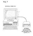
- Fig. 7 shows a personal computer and an external data-storing device, which are coupled each other.
- numeral 1 indicates a personal computer, to which an external data-storing device is coupled through a USB cable.
- a bridge system having a conventional ATAPI or a conventional SCSI, serving as an interface is added to an external data-storing unit (such as an inhouse-MOD, an inhouse-HDD, an inhouse-CD-R/RW, etc., so to speak).
- an external data-storing unit such as an inhouse-MOD, an inhouse-HDD, an inhouse-CD-R/RW, etc., so to speak.
- the meritorious solution has been to develop or purchase the bridge system for converting the ATAPI or the SCSI into the USB or the IEEE1394 interface, in order to externally connect it to the personal computer.
- Fig. 8 shows an example of an outsight configuration of an external data-storing device having the USB or the IEEE1394 interface.
- This configuration makes conventional external data-storing unit 10 usable by adding bridge system 20 to conventional external data-storing unit 10.
- Bridge system 20 is assembled by mounting various kinds of necessary parts onto the circuit board.
- numerals 21, 22, 23 and 24 indicate a power jack, a power switch, a USB or an IEEE1394 connector and an ATAPI or a SCSI connector, respectively, and those are connected onto bridge system 20.
- the bridge system allows the data-storing unit having a conventional ATAPI or a conventional SCSI to be utilized as the data-storing device being active with the USB or the IEEE1394 interface.
- USB connecting ports One or at most two of USB connecting ports has/have been equipped in a conventional personal computer put in the market, and as for IEEE1394 connecting ports, only one port has been allocated for its purpose in the personal computer. Therefore, when a certain small number of devices occupy those USB or IEEE1394 connecting ports, other devices could not be connected to the personal computer.
- a unit named "Hub” has been provided as a "data-distributing" unit, which makes a “multiple-distribution wiring" possible.
- a data-storing device which employs the abovementioned interface and makes it possible to bilaterally supply the power current between the data-storing device and other devices coupled through the interface and to operate the whole system including the coupled devices in a good power balance by controlling the power-supplying mode corresponding to the states of the devices.
- USB Universal Serial Bus
- IEEE1394 IEEE1394
- Such the interface includes a data bus on which data transmit bilaterally, and in addition to the data bus, also includes a path through which an electronic-power for driving a device can be supplied to the device.
- USB interfaces There have been two kinds of the USB interfaces, one of which is a low-speed version having a communication rate of 1.5 Mbps, and another one of which is a high-speed version having a communication rate of 12 Mbps.
- a USB cable comprising a pair of signal lines and a pair of power lines.
- the USB interface can be utilized for connecting 127 peripheral devices at maximum, and suites applications of the plug-and-play mode.
- peripheral devices such as a keyboard, a mouse, a tablet, a FDD, etc.
- the other peripheral device which consumes relatively large amount of electronic power, incorporates a power unit to supply the power current by itself (a self-powered mode).
- the IEEE1394 bus is a serial bus, which is also called as the serial SCSI, the FireWire or the iLINK, etc., and makes it possible to communicate each other at 400 Mbps as a maximum rate with a cable comprising two pairs of signal lines and one pair of power lines.
- the IEEE1394 bus is frequently utilized for communicating movie-image data or still-image data between a video camera and the personal computer.
- a FDD a Floppy-Disk Drive
- a MOD a Magneto-Optics Drive
- a HDD a Hard-Disk Drive
- a CDD a Compact-Disk Drive
- a CD-R/RW a Compact-Disk Drive Recordable / Rewritable
- a DVDD a Digital Video-Disk Drive or Digital Versatile Disk Drive
- a ZipD a high-capacity floppy-disk drive
- Fig. 1 shows an illustrative block-diagram of the first embodiment of the present invention.
- Numeral 1 indicates a personal computer, having USB connecting port UP, serving as a USB interface.
- Personal computer 1 is coupled to data-storing device 2, embodied in the present invention, through USB cable UC1, one end of which is connected to USB connecting port UP, and another end of which is connected to first USB connecting port U1 of data-storing device 2.
- USB cable UC1 comprises data communication path DB, indicated by the line having arrows at both ends, and power-supplying path PB, indicated by the bold line.
- the bilateral data communication is performed through data communication path DB, while the power current is supplied through power supplying path PB, and both are assembled as one cable.
- USB interface circuit USB-I/F having first USB connecting port U1 and second USB connecting port U2, and bridge section BC are equipped in the interior of data-storing device 2.
- USB interface itself comprises data communication path DB and power-supplying path PB as mentioned above
- personal computer 1 supplies the electric power for driving floppy-disk drive FDD through USB interface circuit USB-I/F and further through bridge section BC, while performing the bilateral data communication with data-storing device 2.
- bridge section BC conducts a data/signal converting operation so that personal computer 1 can recognize floppy-disk drive FDD as a USB device.
- the electronic power is supplied to floppy-disk drive FDD through bridge section BC in the configuration shown in Fig. 1, it is also applicable that the power-supplying path and the data communication path are separately disposed in the interior of data-storing device 2.
- data-storing device 2 comprises a plurality of USB connecting ports
- another device can be further coupled to data-storing device 2 by using second USB connecting port U2, which is not used for coupling to personal computer 1.
- the electronic power for driving such "the other device” is supplied from personal computer 1 through the USB interface.
- pen-tablet PT having a feature of low-power consumption, is coupled to data-storing device 2 through second USB connecting port U2 in the first embodiment shown in Fig. 1, it is also possible to connect a keyboard, mouse, etc., which have a feature of low-power consumption as well.
- Fig. 2 shows an illustrative block-diagram of the second embodiment of the present invention.
- the same structural elements as those shown in Fig. 1 are denoted by the same reference numerals.
- data-storing device 2 comprises USB interface circuit USB-I/F, bridge section BC, magneto-optics drive MOD serving as a data-storing unit, first USB connecting port U1 and second USB connecting port U2, and further, power-supply unit PS, serving as a power-supply section of the device.
- the electronic power for driving magneto-optics drive MOD is supplied from power-supply unit PS. Therefore, provided with the power-supply section of the device, which supplies the auxiliary power current to the data-storing unit, it becomes possible that the data-storing device consuming a large amount of electronic power is coupled to the personal computer and another device is further coupled to the data-storing device through the USB interface.
- personal computer 1 supplies the electronic power for driving USB interface circuit USB-I/F and bridge section BC in the configuration shown in Fig. 2, it is also possible that power-supply unit PS supplies the electronic power for driving them, instead of personal computer 1.
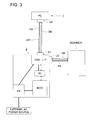
- FIG. 3 shows an illustrative block-diagram of the third embodiment of the present invention.
- the same structural elements as those shown in Fig. 1 and Fig. 2 are denoted by the same reference numerals.
- data-storing device 2 comprises USB interface circuit USB-I/F, bridge section BC, magneto-optics drive MOD serving as a data-storing unit, first USB connecting port U1 and second USB connecting port U2, and further, power-supply unit PS, serving as a power-supply section of the device, as well as that in the configuration of the second embodiment. It is possible, however, that the electronic power generated by power-supply unit PS can be further supplied to another device through power-supplying path PB included in USB interface circuit USB-I/F, by utilizing second USB connecting port U2, which is not used for the connection to personal computer 1.
- an exemplified scanner is coupled to data-storing device 2.
- the electronic power other than the power current supplied from the personal computer can be supplied to another device coupled to the data-storing device through the USB interface, it becomes possible that the other device of high-power consumption can be sufficiently driven by the electronic power supplied from power-supply unit PS without occurring any trouble.
- many peripheral devices can be coupled to the Hub, which is coupled to the data-storing device through second USB connecting port U2.
- personal computer 1 supplies the electronic power for driving USB interface circuit USB-I/F and bridge section BC in the configuration shown in Fig. 3, it is also possible that power-supply unit PS supplies the electronic power for driving them, instead of personal computer 1, as well.
- Fig. 4 shows an illustrative block-diagram of the fourth embodiment of the present invention.
- the same structural elements as those shown in Figs. 1 - 3 are denoted by the same reference numerals.
- data-storing device 2 comprises USB interface circuit USB-I/F, bridge section BC, magneto-optics drive MOD serving as a data-storing unit, first USB connecting port U1 and second USB connecting port U2, and further, power-supply unit PS, serving as a power-supply section of the device, as well as that in the configurations of the second and third embodiments.
- power-supply unit PS serving as a power-supply section of the device, as well as that in the configurations of the second and third embodiments.
- the electronic power generated by power-supply unit PS can be further supplied to another device through power-supplying path PB included in USB interface circuit USB-I/F, by utilizing second USB connecting port U2, which is not used for the connection to personal computer 1.
- the feature of the fourth embodiment lies on a point that data-storing device 2 comprises power controller PCntrl, under the controlling actions of which the electronic power supplied through power-supplying path PB included in USB cable UC1 can be adjusted.
- the fourth embodiment is featured by the point that, when the electronic power generated by the power-supply section of the data-storing device is supplied to another device, power controller PCntrl can adjust an amount of electronic power to be supplied to the other device.
- Data-storing device 2 is coupled to personal computer 1 with USB cable UC1, which comprises data communication path DB and power-supplying path PB.
- USB cable UC1 has a power-supplying function as well as a bilateral data communicating function, and is connected to first USB connecting port U1.
- USB interface circuit USB-I/F having first USB connecting port U1 and second USB connecting port U2 as aforementioned, is equipped in the interior of data-storing device 2.
- first USB connecting port U1 is utilized for the connection with personal computer 1
- second USB connecting port U2 is utilized for the connection with another device.
- an exemplified scanner is coupled to data-storing device 2 through second USB connecting port U2.
- USB interface circuit USB-I/F is coupled to power controller PCntrl, serving as a power controlling section.
- Power-supply unit PS serving as a power-supply section of the device, converts an alternative power current fed from an external AC power source to a direct power current, which is supplied to magneto-optics drive MOD, USB interface circuit USB-I/F, etc.
- the default interface of magneto-optics drive MOD is converted to the USB interface through bridge section BC, serving as a data bridging circuit. Accordingly, magneto-optics drive MOD can be utilized as a device having the USB interface by converting data, even if the default interface of magneto-optics drive MOD is not the USB interface (for instance, ATAPI, SCSI, etc.). It is needless to say, however, that bridge section BC is not necessary, when the default interface of magneto-optics drive MOD is the USB interface.
- power-supply unit PS supplies the electronic power for driving bridge section BC in the fourth embodiment, it is also applicable that the electronic power for driving bridge section BC is supplied through USB interface circuit USB-I/F.
- Power controller PCntrl to which USB interface circuit USB-I/F supplies the electronic power, conducts controlling actions for adjusting the power-distributing operation from power-supply unit PS to each of the devices and units. Concretely speaking, power controller PCntrl controls an amount of electronic power to be supplied to the device coupled through second USB connecting port U2, while supplying the electronic power to magneto-optics drive MOD.
- the power current is adjusted so as to maintain at least a minimum amount of power current required for flowing into the power current path as specified in the USB or the IEEE1394 standard. Conversely, the power current is also adjusted so as not to exceed a maximum amount of power current, being an upper-limit durable for the power current path included in the interface.
- Such the upper-limit or the lower-limit can be freely set at a value within the scope of the standards or the specifications of the product.
- power-supply unit PS supplies the power current for driving power controller PCntrl.
- the electronic power outputted from personal computer 1 can be directly supplied to the other device, coupled to data-storing device 2, through second USB connecting port U2.
- bridge section BC is coupled to magneto-optics drive MOD through power controller PCntrl.
- power-supply unit PS supplies the total power current only to power controller PCntrl, which distributes the total power current among another device and units.
- the fifth embodiment will be detailed in the following.
- the configuration of the fifth embodiment is substantially the same as that of the fourth embodiment.
- power controller PCntrl serving as a power controlling section, controls the switching status of the power current supplied to the other device through second USB connecting port U2, in response to whether or not power-supply unit PS, serving as a power-supply section of the device, is turned ON.
- power controller PCntrl determines that power-supply unit PS has a sufficient capacity for supplying the power current, and turns ON the power current to be supplied to the other device coupled through second USB connecting port U2.
- power-supply unit PS is not directly coupled to power controller PCntrl in the configuration shown in Fig. 4, it is also applicable that those are directly coupled each other to detect the operating status of power-supply unit PS.
- the abovementioned controlling operation makes it possible to optimally control the power-supplying status for the device, coupled to data-storing device 2, in response to the operating status of power-supply unit PS.
- the sixth embodiment will be detailed in the following.
- the configuration of the sixth embodiment is substantially similar to those of the fourth and fifth embodiments, the difference between them lies on the point that the configuration of the sixth embodiment comprises a detecting section to detect and collect information pertaining to the device currently coupled.
- the controlling operation in the sixth embodiment which is performed by the power controlling section on the basis of detected results of the detecting section, is also different from those in the fourth and fifth embodiments.
- the detecting section detects the devices coupled through USB interface circuit USB-I/F, so that power controller PCntrl, serving as a power controlling section, adjusts the power-supplying mode on the basis of the information detected by the detecting section.
- the distinguished block illustrated in the block-diagram shown in Fig. 5 is sensor SE, serving as a detecting section.
- the sensor SE has a function of obtaining information pertaining to the device currently coupled through USB interface circuit USB-I/F.
- sensor SE detects all of the devices and units currently coupled through USB interface circuit USB-I/F, it is needless to say that sensor SE also detects magneto-optics drive MOD through bridge section BC.
- sensor SE is coupled to magneto-optics drive MOD through USB interface circuit USB-I/F and bridge section BC
- the configuration in which sensor SE is directly coupled to bridge section BC or magneto-optics drive MOD is also applicable.
- power controller PCntrl serving as a controlling section, receives the information pertaining to the devices and units currently coupled and detected by sensor SE, power controller PCntrl sends command signals in response to the states of the devices to power-supply unit PS.
- the DC power source generated by converting the AC power source fed from the outside, can be effectively distributed to the devices and units concerned by performing the abovementioned controlling actions, it becomes possible to harmonize the power conditions of the external devices coupled through the interface, resulting in improvement of the efficiency of the whole system.
- the connecting status of the external devices is periodically detected with a predetermined time interval, to change the power-supplying status in a time domain.
- power controller PCntrl has a function of the sensor.
- Such the embodiment would desirably simplify the circuit configuration, resulting in cost-reduction of the data-storing device.
- the seventh embodiment is a variation of the sixth embodiment described in the above.
- USB-interface circuit USB-I/F makes it possible to supply the power current from the original connecting device (mainly being a personal computer) to the device(s) coupled through it.
- an amount of the abovementioned power current supplied from the original connecting device is not an object to be controlled by the power controller mentioned above, it is possible to guarantee a minimum amount of the power current for driving the devices coupled through the interface, while performing the controlling actions for the power supply.
- the eighth embodiment is a variation of the sixth embodiment described in the above, as well as the seventh embodiment.
- power controller PCntrl controls the power-supplying mode of the whole system, so as to share a total amount of the power current supplied from the original connecting device and the other power current supplied from power-supply unit PS among the devices coupled through the interface.
- the suppliable power current can be shared among the devices coupled through the interface on the basis of the overall needs of the devices, it becomes possible to efficiently operate the whole system without generating any power loss.
- the power current for driving power controller PCntrl is supplied from personal computer 1 through USB-interface circuit USB-I/F, as aforementioned.
- power controller PCntrl can be always activated, even if power-supply unit PS is deactivated.
- power controller PCntrl has a function of switching the power sources for driving itself.
Landscapes
- Engineering & Computer Science (AREA)
- Theoretical Computer Science (AREA)
- General Engineering & Computer Science (AREA)
- Physics & Mathematics (AREA)
- General Physics & Mathematics (AREA)
- Power Engineering (AREA)
- Human Computer Interaction (AREA)
- Computer Hardware Design (AREA)
- Power Sources (AREA)
Abstract
Description
in the data-storing device provided with the interface, which has two paths including a data path for transmitting and receiving data and a power source path through which an operating power current is received from an original connecting device and/or the operating power current is supplied to coupled devices, and a data-storing unit,
the data-storing device comprises a plurality of interface connecting ports.
in the data-storing device provided with the interface, which has two paths including a data path for transmitting and receiving data and a power source path through which an operating power current is received from an original connecting device and/or the operating power current is supplied to coupled devices, and a data-storing unit,
the data-storing device comprises a plurality of interface connecting ports and a power-supply section to supply a power current for driving the data-storing unit.
in the data-storing device provided with the interface, which has two paths including a data path for transmitting and receiving data and a power source path through which an operating power current is received from an original connecting device and/or the operating power current is supplied to coupled devices, and a data-storing unit,
the data-storing device comprises a plurality of interface connecting ports and a power-supply section to supply a power current for driving the data-storing unit, and a part of the first power current supplied from the power-supply section through the power source path is supplied to the device coupled through the interface connecting port.
in the data-storing device provided with the interface, which has two paths including a data path for transmitting and receiving data and a power source path through which an operating power current is received from an original connecting device and/or the operating power current is supplied to coupled devices, and a data-storing unit,
the data-storing device comprises a plurality of interface connecting ports, a power-supply section to supply a power current for driving the data-storing unit, and a power-source controlling section to adjust an amount of power current to be supplied, when a part of the first power current supplied from the power-supply section through the power source path is supplied to the device coupled through the interface connecting port.
in the data-storing device provided with the interface, which has two paths including a data path for transmitting and receiving data and a power source path through which an operating power current is received from an original connecting device and/or the operating power current is supplied to coupled devices, and a data-storing unit,
the data-storing device comprises a plurality of interface connecting ports, a power-supply section to supply a power current for driving the data-storing unit, and a power-source controlling section to supply a power current to the coupled device with adding new power source to the power-source path from the power-supply section only when the power-supply section is activated, in case that the operating power source supplied from the original connecting device through a certain interface connecting port is supplied to the device coupled through another interface connecting port.
in the data-storing device provided with the interface, which has two paths including a data path for transmitting and receiving data and a power source path through which an operating power current is received from an original connecting device and/or the operating power current is supplied to coupled devices, and a data-storing unit,
the data-storing device comprises a plurality of interface connecting ports, a power-supply section to supply a power current for driving the data-storing unit wherein the power-supply section is also capable of supplying a power current to the coupled device, a detecting section to detect power-source information, which is necessary for the device and the other device, through the data path in regard to the devices including the data-storing unit and coupled through the interface, and a power-source controlling section to adjust the share of the amounts of the power currents to be distributed, on the basis of the power-source information obtained by the detecting section, when supplying the power currents to the devices including the data-storing unit and coupled through the interface.
when supplying the power currents to the devices including the data-storing unit and coupled through the interface, an operating power source, supplied from the original connecting device coupled through the interface, passes through.
when supplying the power currents to the devices including the data-storing unit and coupled through the interface, the power-supply section adjust the share of a total amount of a power current, supplied from the original connecting device coupled through the interface connecting port, and another power current, supplied from the power-supply section.
the power-supply section is driven by the operating power source supplied from the original connecting device.
the power-supply section is driven by the power source supplied from the power-supply section when the the power-supply section is activated, while the power-supply section is driven by the operating power source supplied from the original connecting device when the power-supply section is activated.
Claims (14)
- A device for storing data, comprising:an interfacing circuit that includes a data communication path through which said data can be bilaterally communicated between said device and an external device, which is coupled to said device with an interface cable, and a power-supplying path through which a power current can be bilaterally supplied between said device and said external device, wherein said interface cable also includes said data communication path and said power-supplying path;a data-storing unit to store said data sent from said interfacing circuit; anda plurality of interface connecting ports serving as input/output terminals of said interfacing circuit, wherein said interface cable can be connected to one of said interface connecting ports.
- The device of claim 1,
wherein said external device is a personal computer and said data-storing unit is a magneto-optics disk drive, and a peripheral device can be also coupled to said device through another one of said interface connecting ports with another interface cable. - A device for storing data, comprising:an interfacing circuit that includes a data communication path through which said data can be bilaterally communicated between said device and an external device, which is coupled to said device with a first interface cable, and a power-supplying path through which a power current can be bilaterally supplied between said device and said external device, wherein said first interface cable also includes said data communication path and said power-supplying path;a data-storing unit to store said data sent from said interfacing circuit;a plurality of interface connecting ports serving as input/output terminals of said interfacing circuit, wherein said first interface cable can be connected to a first interface connecting port being one of said interface connecting ports; anda power-supply section to supply a first power current for driving said data-storing unit.
- The device of claim 3,
wherein a peripheral device can be also coupled to said device through a second interface connecting port being another one of said interface connecting ports with a second interface cable. - The device of claim 4,
wherein a second power current, being a part of said first power current outputted by said power-supply section, is also supplied to said peripheral device through said power-supplying path included in said second interface cable connected to said second interface connecting port. - The device of claim 5,
wherein said external device is a personal computer and said data-storing unit is a magneto-optics disk drive. - The device of claim 5, further comprising:a power controller to control an amount of said second power current to be supplied to said peripheral device.
- The device of claim 5, further comprising:a power controller to control said interfacing circuit in such a manner that a third power current, supplied from said external device through said first interface connecting port, is further supplied to said peripheral device through said second interface connecting port, only when said power controller detects that said power-supply section is activated.
- A device for storing data, comprising:an interfacing circuit that includes a data communication path through which said data can be bilaterally communicated between said device and an external device, which is coupled to said device with a first interface cable, and a power-supplying path through which a power current can be bilaterally supplied between said device and said external device, wherein said interface cable also includes said data communication path and said power-supplying path;a data-storing unit to store said data sent from said interfacing circuit;a plurality of interface connecting ports serving as input/output terminals of said interfacing circuit, wherein said first interface cable can be connected to a first interface connecting port being one of said interface connecting ports, and plural peripheral devices are coupled to said device with plural interface cables through said interface connecting ports other than said first interface connecting port;a power-supply section to supply power currents for driving said peripheral devices and for driving units and sections included in said device, wherein said units includes said data-storing unit;a detecting section to detect power-status information sets pertaining to amounts of said power currents required for driving said peripheral devices coupled through said interface connecting ports and required for driving said units and sections included in said device; anda power controller to adjust each of said amounts of said power currents to be distributed among said peripheral devices, said units and sections, on the basis of said power-status information sets detected by said detecting section.
- The device of claim 9,
wherein a power current, supplied from said external device through said first interface connecting port and further supplied to one of said peripheral devices through one of said interface connecting ports, passes through said interfacing circuit as it is. - The device of claim 9,
wherein said power controller controls a power-supplying mode of said device, so as to share a total amount of a power current, supplied from said external device coupled through said first interface connecting port, and another power current, supplied from said power-supply unit, among said peripheral devices coupled through said interface connecting ports other than said first interface connecting port. - The device of claim 9,
wherein said external device is a personal computer and said data-storing unit is a magneto-optics disk drive. - The device of claim 9,
wherein said power controller is driven by a power current supplied from said external device through said first interface connecting port. - The device of claim 9,
wherein said power controller is driven by a power current supplied from said power-supply section when said power-supply section is activated, while said power controller is driven by a power current supplied from said external device through said first interface connecting port when said power-supply section is deactivated.
Applications Claiming Priority (2)
| Application Number | Priority Date | Filing Date | Title |
|---|---|---|---|
| JP2000347135A JP2002149284A (en) | 2000-11-14 | 2000-11-14 | Storage apparatus |
| JP2000347135 | 2000-11-14 |
Publications (2)
| Publication Number | Publication Date |
|---|---|
| EP1207458A2 true EP1207458A2 (en) | 2002-05-22 |
| EP1207458A3 EP1207458A3 (en) | 2004-02-04 |
Family
ID=18820915
Family Applications (1)
| Application Number | Title | Priority Date | Filing Date |
|---|---|---|---|
| EP01126866A Withdrawn EP1207458A3 (en) | 2000-11-14 | 2001-11-12 | Data-storing device |
Country Status (3)
| Country | Link |
|---|---|
| US (1) | US6845422B2 (en) |
| EP (1) | EP1207458A3 (en) |
| JP (1) | JP2002149284A (en) |
Cited By (1)
| Publication number | Priority date | Publication date | Assignee | Title |
|---|---|---|---|---|
| ES2381276A1 (en) * | 2010-10-04 | 2012-05-24 | Destell Gestion, S.L. | Device for storage and transmission-selective data reception. (Machine-translation by Google Translate, not legally binding) |
Families Citing this family (19)
| Publication number | Priority date | Publication date | Assignee | Title |
|---|---|---|---|---|
| GB2374259B (en) * | 2001-04-06 | 2004-04-21 | Nokia Corp | Universal serial bus circuit |
| JP3675394B2 (en) * | 2001-11-30 | 2005-07-27 | ソニー株式会社 | Communication device |
| TW564349B (en) * | 2002-02-27 | 2003-12-01 | Acer Labs Inc | Method and related apparatus for controlling transmission interface of external device of computer system |
| JP4316838B2 (en) * | 2002-05-16 | 2009-08-19 | 富士通株式会社 | Device drivers and devices |
| US20040103223A1 (en) * | 2002-11-26 | 2004-05-27 | Motorola, Inc. | USB accessory adaptor |
| US7679791B2 (en) * | 2003-01-06 | 2010-03-16 | Chun-Jen Chen | Method for selecting and adjusting scanner illuminant |
| US7114085B1 (en) * | 2003-04-24 | 2006-09-26 | Audavi Corporation | Portable storage device startup |
| US7400469B2 (en) | 2003-09-16 | 2008-07-15 | Spectra Logic Corporation | Magazine-based library |
| US7508621B2 (en) * | 2003-06-26 | 2009-03-24 | Spectra Logic Corporation | Magazine-based data cartridge library |
| DE20312002U1 (en) * | 2003-08-02 | 2003-10-30 | Power 7 Technology Corp., Chung-Ho, Taipeh | Digital data transmission device |
| JP2007299146A (en) * | 2006-04-28 | 2007-11-15 | Mitsumi Electric Co Ltd | Information processing apparatus and video receiving apparatus |
| JP2012019368A (en) * | 2010-07-08 | 2012-01-26 | Nikon Corp | Image preservation device |
| US9502079B2 (en) | 2011-02-01 | 2016-11-22 | 3M Innovative Properties Company | Passive interface for an electronic memory device |
| US8400728B2 (en) | 2011-05-23 | 2013-03-19 | Spectra Logic Corp. | Efficient moves via repository |
| US9368148B2 (en) | 2011-10-25 | 2016-06-14 | Spectra Logic, Corporation | Efficient moves via spare chamber |
| US9159357B2 (en) | 2013-08-14 | 2015-10-13 | Spectra Logic Corporation | Efficient moves via repository |
| JP2019128761A (en) * | 2018-01-24 | 2019-08-01 | キヤノン株式会社 | Electronic device, and control method therefor and program |
| CN110162497A (en) * | 2019-04-15 | 2019-08-23 | 深圳市普威技术有限公司 | Interconnecting device, adapting system, host system and the terminal system of data-interface |
| KR20250084610A (en) * | 2023-12-04 | 2025-06-11 | 삼성전자주식회사 | Electronic device and operating method for the same |
Family Cites Families (11)
| Publication number | Priority date | Publication date | Assignee | Title |
|---|---|---|---|---|
| US5675813A (en) | 1995-10-26 | 1997-10-07 | Microsoft Corporation | System and method for power control in a universal serial bus |
| US5784581A (en) * | 1996-05-03 | 1998-07-21 | Intel Corporation | Apparatus and method for operating a peripheral device as either a master device or a slave device |
| JP3747564B2 (en) * | 1997-04-28 | 2006-02-22 | 株式会社日立製作所 | Display device |
| DE69834316T2 (en) * | 1997-07-17 | 2006-09-21 | Matsushita Electric Industrial Co., Ltd., Kadoma | DATA MANAGEMENT DEVICE |
| US6678464B1 (en) * | 1997-12-26 | 2004-01-13 | Canon Kabushiki Kaisha | Preventing copying of digital information |
| JPH11353061A (en) * | 1998-06-09 | 1999-12-24 | Casio Electronics Co Ltd | Power control device |
| JP3562563B2 (en) * | 1998-06-12 | 2004-09-08 | ティアック株式会社 | Data storage device using exchangeable recording medium |
| JP2000214953A (en) | 1999-01-25 | 2000-08-04 | Fujitsu Ltd | Function expansion device for electronic equipment |
| JP2000214954A (en) | 1999-01-26 | 2000-08-04 | Mitsubishi Electric Corp | Computer |
| US20020114613A1 (en) * | 2001-02-16 | 2002-08-22 | Sony Corporation | Audio/video editing in digital network recorders |
| US6691187B1 (en) * | 2001-07-02 | 2004-02-10 | Canon U.S.A., Inc. | Printer-based interface with removable digital storage media |
-
2000
- 2000-11-14 JP JP2000347135A patent/JP2002149284A/en active Pending
-
2001
- 2001-11-09 US US09/986,614 patent/US6845422B2/en not_active Expired - Fee Related
- 2001-11-12 EP EP01126866A patent/EP1207458A3/en not_active Withdrawn
Cited By (1)
| Publication number | Priority date | Publication date | Assignee | Title |
|---|---|---|---|---|
| ES2381276A1 (en) * | 2010-10-04 | 2012-05-24 | Destell Gestion, S.L. | Device for storage and transmission-selective data reception. (Machine-translation by Google Translate, not legally binding) |
Also Published As
| Publication number | Publication date |
|---|---|
| JP2002149284A (en) | 2002-05-24 |
| US6845422B2 (en) | 2005-01-18 |
| EP1207458A3 (en) | 2004-02-04 |
| US20020057608A1 (en) | 2002-05-16 |
Similar Documents
| Publication | Publication Date | Title |
|---|---|---|
| US6845422B2 (en) | Data-storing device | |
| US6317839B1 (en) | Method of and apparatus for controlling supply of power to a peripheral device in a computer system | |
| US6105097A (en) | Device and method for interconnecting universal serial buses including power management | |
| JP3861614B2 (en) | Electronic device having interface terminal | |
| US7007175B2 (en) | Motherboard with reduced power consumption | |
| US6841898B2 (en) | Automatic power supply selector for a ACPI-compliant PCI devices | |
| US7231485B2 (en) | Universal serial bus (USB) interface for mass storage device | |
| US7502947B2 (en) | System and method of controlling a graphics controller | |
| US20040200631A1 (en) | Cable and connection module for a universal serial bus interface | |
| KR100386360B1 (en) | Power-on device in computer | |
| EP0778532A2 (en) | An information processing apparatus | |
| KR20030087895A (en) | Double interface CF flash memory card | |
| TWI754183B (en) | Hdd backplane management device | |
| EP1248203B1 (en) | Universal serial bus circuit to detect connection status | |
| US6983383B1 (en) | Method for providing priority to an ac adaptor if the input to the ac adaptor is above a predetermined value even if the power supply via an interface is present | |
| US6218817B1 (en) | Voltage-switching regulator with built-in voltage-switching module for a memory module | |
| US6871252B1 (en) | Method and apparatus for logical detach for a hot-plug-in data bus | |
| EP1766497B1 (en) | System and method for routing data and power to external devices | |
| US6647435B1 (en) | Method and apparatus system with first and second controller connected via uart chip for controlling peripheral device of computer system in second power mode | |
| JP2002073219A (en) | Interface device equipped with part for supplying power to external device and method for supplying power to external device | |
| KR101206504B1 (en) | External type multi-device bay | |
| US20020172115A1 (en) | Disk drive device | |
| KR200230770Y1 (en) | An external storage device having compatibility to multi-interfaces | |
| KR20120047153A (en) | Control board, external type multi-device bay having the control board and system using thereof | |
| US6970349B2 (en) | Expandale modular storage unit |
Legal Events
| Date | Code | Title | Description |
|---|---|---|---|
| PUAI | Public reference made under article 153(3) epc to a published international application that has entered the european phase |
Free format text: ORIGINAL CODE: 0009012 |
|
| AX | Request for extension of the european patent |
Free format text: AL;LT;LV;MK;RO;SI |
|
| PUAL | Search report despatched |
Free format text: ORIGINAL CODE: 0009013 |
|
| AK | Designated contracting states |
Kind code of ref document: A3 Designated state(s): AT BE CH CY DE DK ES FI FR GB GR IE IT LI LU MC NL PT SE TR |
|
| AX | Request for extension of the european patent |
Extension state: AL LT LV MK RO SI |
|
| RIC1 | Information provided on ipc code assigned before grant |
Ipc: 7G 06F 3/06 B Ipc: 7G 06F 13/38 B Ipc: 7G 06F 13/40 A |
|
| 17P | Request for examination filed |
Effective date: 20040804 |
|
| AKX | Designation fees paid |
Designated state(s): AT BE CH CY DE DK ES FI FR GB GR IE IT LI LU MC NL PT SE TR |
|
| AXX | Extension fees paid |
Extension state: SI Payment date: 20040804 Extension state: RO Payment date: 20040804 Extension state: MK Payment date: 20040804 Extension state: LV Payment date: 20040804 Extension state: LT Payment date: 20040804 Extension state: AL Payment date: 20040804 |
|
| 17Q | First examination report despatched |
Effective date: 20080530 |
|
| STAA | Information on the status of an ep patent application or granted ep patent |
Free format text: STATUS: THE APPLICATION IS DEEMED TO BE WITHDRAWN |
|
| 18D | Application deemed to be withdrawn |
Effective date: 20081010 |