EP1766497B1 - System and method for routing data and power to external devices - Google Patents
System and method for routing data and power to external devices Download PDFInfo
- Publication number
- EP1766497B1 EP1766497B1 EP05760528.9A EP05760528A EP1766497B1 EP 1766497 B1 EP1766497 B1 EP 1766497B1 EP 05760528 A EP05760528 A EP 05760528A EP 1766497 B1 EP1766497 B1 EP 1766497B1
- Authority
- EP
- European Patent Office
- Prior art keywords
- power
- booster
- rail
- nominal voltage
- power rail
- Prior art date
- Legal status (The legal status is an assumption and is not a legal conclusion. Google has not performed a legal analysis and makes no representation as to the accuracy of the status listed.)
- Active
Links
Images


Classifications
-
- G—PHYSICS
- G06—COMPUTING; CALCULATING OR COUNTING
- G06F—ELECTRIC DIGITAL DATA PROCESSING
- G06F1/00—Details not covered by groups G06F3/00 - G06F13/00 and G06F21/00
- G06F1/26—Power supply means, e.g. regulation thereof
- G06F1/266—Arrangements to supply power to external peripherals either directly from the computer or under computer control, e.g. supply of power through the communication port, computer controlled power-strips
Description
- The present invention is related to data transmission, and more particularly to a system and method for routing power to external devices.
- Universal Serial Bus (USB) provides both data and power to downstream devices. Under the standard, each USB interface includes two data lines, plus power and ground. The maximum power available under USB for a downstream device is 500mA@5V (2.5W). Any device demanding higher power must use an external power source, such as a power brick, eliminating some of the simplicity and advantage of a single cable connection for both power and data.
- USB+ was developed as a way of providing additional power to external devices without the use of an external power brick. A USB+ connector defines four additional power pins, providing an additional ground conductor and up to 6A of+5V, +12V and +24V power. In contrast to the 2.5W available from standard USB, a single USB+ connector can, therefore, provide up to 144W of power.
- USB ports are standard on any new motherboard today. However, USB+ ports typically are added as either an add-on card to the PC (e.g., a PCI card) or as a standalone USB+ HUB with its own power supply.
- In case of the external HUB, the external power supply provides the power distributed to the attached devices via the USB+ connector.
- In case of a PCI add-on card the power typically comes from the internal power supply of the PC. The +5V or +12V comes directly from the internal power supply and the +24V is boosted from the +12V.
- Today's competitive PC marketplace demands that the size of the internal power supply of the PC be in line with the projected maximum internal power consumption. Installing a larger power supply than required would increase the cost of the PC. PCs do not, therefore, typically have a great deal of extra power capacity, at least in the low-end units. Therefore, a typical power supply will not have sufficient reserve (unused) power available to provide the up to 144W that could be required for external USB+ devices. In addition, while the sum of the reserve power of the power supplies on all different voltage outputs may be sufficient reserve power, it may not match the power requirements. That is, reserve power may be available on the +5V rail where the demand may be needed on the +12V or +24V or vice-versa.
- Finally, power demand, and the amount of power that a power supply can provide, vary as a function of time, temperature and operating mode. A PC can be reconfigured by adding either external or internal devices, activating or deactivating high-powered functions.
- What is needed is a system and method for routing power to external devices that addresses the issues raised above and other issues that will become apparent in reading the following description of the present invention.
-
US5852544 A (Lee et al. ) discloses a computer assembly containing an internal power supply that powers both peripherals located within the housing of a computer and peripherals located external to the housing of the computer. - In the drawings, like numerals describe substantially similar components throughout the several views.
-
Figure 1 illustrates a system that routes power from power rails of a power supply to an external device; -
Figures 2-4 illustrate embodiments of the system ofFigure 1 ; -
Figure 5 illustrates a system having a power router which operates automatically to draw power from two or more sources; and -
Figure 6 illustrates an embodiment of the system ofFigure 5 . - In the following detailed description of the preferred embodiments, reference is made to the accompanying drawings that form a part hereof, and in which is shown by way of illustration specific embodiments in which the invention may be practiced. It is to be understood that other embodiments may be utilized and structural changes may be made without departing from the scope of the present invention.
- In the following description and claims, the terms "coupled" and connected," along with their derivatives, may be used. It should be understood that these terms are not intended as synonyms for each other. Rather, in particular embodiments, "connected" may be used to indicate that two or more elements are in direct physical or electrical contact with each other. However, "coupled" may also mean that two or more elements are not in direct contact with each other, but yet still co-operate or interact with each other.
- As noted above, personal computers do not typically have a great deal of extra power capacity. Furthermore, even if the sum of the reserve power of the power supplies on all different voltage outputs is sufficient to power an external device, the form in which that power is available may not match the needs of the external device. That is, reserve power may be available on the +5V rail where the demand may be needed on the +12V or +24V or vice-versa.
- A system that routes power dynamically from power rails of a
power supply 16 internal to acomputer 10 to an external device is shown inFig. 1 . In the example shown inFig. 1 , acomputer 10 includes ahousing 12. Aprocessor 14,power supply 16 andcommunications interface 20 are encased withinhousing 12. In one embodiment (not shown),processor 14 includescommunications interface 20. -
Processor 14 communicates with external devices throughcommunications interface 20 andconnector 18.Connector 18 also includespower conductors conductors - In one embodiment,
computer 10 provides the first and second nominal voltages viabooster 26 andpower router 28.Power router 28 is connected topower supply 16 and tobooster 26 and routes power toconductors Fig.2 . - In the embodiment shown in
Fig. 2 ,router 28 includes aswitch 30 used to select between a power rail ofpower supply 16 and the output ofbooster 26. In one such embodiment,conductor 22 is connected to the +5V rail ofpower supply 16, whileconductor 24 is connected to switch 30. Booster 26 is connected to the +5V rail ofpower supply 16 and outputs +12V power. Switch 30, then, is used to select between the +12V power rail ofpower supply 16 and the +12V output ofbooster 26. - In one such embodiment,
processor 14 senses power demand on each of the +5V and +12V power rails ofpower supply 16 andsets switch 30 to draw power from the rail with the lowest load. In another embodiment, circuitry other thanprocessor 14 senses power demand on each of the +5V and +12V power rails ofpower supply 16 and setsswitch 30 to draw power from the rail with the lowest load. Such an embodiment is shown inFigs. 5 and6 and will be discussed below. - In one comparative embodiment not describing the claimed invention,
switch 30 is replaced with a jumper. The routing logic can be as simple as a jumper as long as the user has prior information of the expected power demand. - One comparative embodiment of a manual jumper routing which is not describing the claimed invention is a configuration where the +12V output is either directly connected to the +12V input or it is generated via
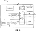
power booster circuitry 26 from the +5V output. This reduces demand on the +12V input and leaves more reserves on the +12V input. In one such embodiment, this extra reserve of the +12V input is boosted to +24V and supplies a +24V output (as shown inFig. 3 ). - In the embodiment shown in
Fig. 3 ,connector 18 includes athird power conductor 34 connected to abooster 32. In one such embodiment,booster 32 boosts power from the +12V rail ofpower supply 16 to +24V. In another embodiment (not shown), a booster connected to the +5V rail ofpower supply 16 provides the boost to +24V. - The dual booster architecture of
Fig. 3 has some advantages over the single booster architecture ofFigs. 1 and2 . USB+ devices will primarily use the +12V and +24V output as their power source. A single booster architecture can put the entire high power demand on the +12V power rail, quickly exhausting the reserve power. The dual booster approach distributes this power demand over multiple power rails. - In yet another embodiment, +24V is supplied by an
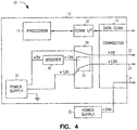
external power supply 36 routed throughcomputer 10 toconductor 34. An example of this is shown inFig. 4 . An optional external power booster supply can also be connected if the overall internal power reserve is not sufficient for the total power demand. The input of this booster supply is typically +24V, but it could be theoretically anything else. - In one embodiment,
power router 28 ofFig. 1 monitors, either by itself or in cooperation withprocessor 14, the load on the +5V and +12V power rails. As power demand increases due to either additional internal or external demand, the corresponding power rail will experience a voltage drop. The power routing circuitry could then route reserve power from power rails having reserve to power rails experiencing heavy demand. - In one
embodiment power router 28 operates automatically to draw power from two or more sources. In one such embodiment, automatic routing circuitry includes power-monitoring circuitry. By actively monitoring the output voltage,power router 28 can detect overload of an individual power rail and route additional reserve power to the power rail under heavy demand. - One such embodiment is shown in
Fig. 5 . In thecomputer 10 ofFig. 5 ,internal power supply 16 provides a first and a second power rail (at +5V and +12V, respectively). Power routing andconversion unit 40 receives power from the first and second power rails and outputs power at a first, second and third nominal voltage. In the example shown, the nominal voltages are +5V, +12V and +24V, but any combination of voltages could be supplied in a similar manner. In the embodiment shown, power routing andconversion unit 40 includesreserve power router 42, output power conditioner 44 andcontrol logic 46.Control logic 46 monitors the first, second and third nominal voltages and adjusts the power drawn byreserve power router 42 from the first and second power rails accordingly, driving, for instance, the +12V power conductor with power selectively drawn from the +12V power rail and from the output ofbooster 26. In one such embodiment,control logic 46 also controls operation of output power conditioner 44. - In one embodiment, power routing and
conversion unit 40 employs a dual booster architecture (such as is shown inFig. 3 ). Such an embodiment is shown inFig. 6 . In the embodiment shown inFig. 6 , the +24V output is boosted out of the +12V power rail and the +12V output is primarily generated from the +12V power rail as well. The +12V output is, however, monitored continuously bycontrol logic 46 and, upon detecting a pre-set minimum threshold, the secondary +5V to +12V booster circuit transfers reserve power from the +5V into the +12V power rail. - One might, for instance, connect a device to the +24V. The primary power booster will transfer power from the +12V input to the +24V output. Additional devices connected either to the +12V or +24V will put more demand on the +12V output causing it to drop the voltage and reaching the minimum threshold. At that point the secondary +5V to +12V booster will transfer power into the +12V rail.
- In another embodiment, power routing and
conversion unit 40 employs a single booster withexternal power supply 36 such as is shown inFig. 4 . In one such embodiment, power routing andconversion unit 40 uses the +24V power input ofexternal power supply 36 to supplement the power available on the +12V or +5V outputs. - The embodiments shown in
Figs. 1-6 could also be sold as kits used to retrofit existingcomputer systems 10. For instance, a PCI card could be used to add powered USB to a computer system. In one such embodiment, power power routing andconversion unit 40 uses the +24V power input ofexternal power supply 36 to supplement the power available on the +12V or +5V outputs. - The embodiments shown in
Figs. 1-6 could also be sold as kits used to retrofit existingcomputer systems 10. For instance, a PCI card could be used to add powered USB to a computer system. In one such embodiment, power routing andconversion unit 40 would be provided with a USB controller in a PCI card form factor in order to provide powered USB. Other serial and parallel communications interfaces could be provided in a similar manner. In one such embodiment, the PCI card includes a connector for connecting the card to an external power supply (such asexternal power supply 36 shown inFigs. 4 and5 ). - In the above discussion and in the attached appendices, the term "computer" is defined to include any digital or analog data processing unit. Examples include any personal computer, workstation, set top box, mainframe, server, supercomputer, laptop or personal digital assistant capable of embodying the inventions described herein. Although specific embodiments have been illustrated and described herein, it
will be appreciated by those of ordinary skill in the art that any arrangement that is calculated to achieve the same purpose may be substituted for the specific embodiment shown.
Claims (13)
- A method of providing power to external devices connected to a computer (10) having a computer housing (12), wherein the computer housing (12) includes an externally accessible connector (18) having a first power conductor (24) and a ground conductor, the method comprising:installing a power supply (16) in the computer housing (12), wherein the power supply (16) includes a ground and a first and a second power rail, wherein the first power rail is at a first nominal voltage and the second power rail is at a second nominal voltage;electrically connecting a first booster (26) to the first power rail, wherein the first booster (26) includes a first booster output and wherein the first booster output is at the second nominal voltage;electrically connecting the second power rail and the output of the booster (26) to a power router (28, 40); anddriving the first power conductor (24) with power selectively drawn from the second power rail and from the booster output, wherein driving includes dynamically converting reserve power available on the first and second power rails to approximately the second nominal voltage and outputting the dynamically converted power to the external device.
- The method according to claim 1, wherein the method further comprises:electrically connecting a second booster (32) to the second power rail, wherein the second booster outputs power at a third nominal voltage; andelectrically connecting an output of the second booster (32) to a second power conductor (34).
- The method according to any of claims 1 and 2, wherein the method further comprises electrically connecting the power and ground conductors to the external device.
- The method according to any of claims 1 and 2, wherein driving the first power conductor (24) includes:sensing a voltage on the first power conductor (24); anddrawing power from the second power rail and from the first booster output as a function of the voltage sensed on the first power conductor (24).
- A system for providing power to external devices connected to a computer (10) having a computer housing (12), a processor (14) installed in the computer housing (12) and a power supply (16) installed in the computer housing (12), wherein the power supply (16) is connected to the processor (14) and wherein the power supply (14) includes a ground rail, a first power rail having a first nominal voltage and a second power rail having a second nominal voltage, wherein the system comprises:a first booster (26) for electrically connecting to the first power rail, wherein the first booster (26) is capable of boosting power from the first power rail to a voltage approximately equal to the second nominal voltage;power routing means (28, 40) for electrically connecting to the first booster and to the second power rail; andan externally accessible connector (18), wherein the connector (18) includes a ground conductor and first and second power conductors (22, 24), the first power conductor (22) for electrically connecting to the first power rail and the second power conductor (24) for electrically connecting to the power routing means (28, 40);wherein the power routing means(28, 40), when electrically connected, drives the second power conductor (24) at approximately the second nominal voltage with power selectively drawn from the first booster (26) and the second power rail, wherein the power routing means (28, 40), when electrically connected, dynamically converts reserve power available on the first and second power rails to approximately the second nominal voltage and outputs the dynamically converted power to the external device.
- The system of claim 5, wherein the system comprises the computer (10).
- The system according to claim 5, wherein the computer (10) further comprises a communications interface (20), connected to the processor (14), for communicating with the external device, wherein the externally accessible connector (18) is configured to be electrically connected to the communications interface (20).
- The system of claims 7, wherein the communications interface (20) includes a serial communications interface.
- The system of claim 7, wherein the communications interface (20) includes a universal serial bus (USB) interface.
- The system of claim 7, wherein the communications interface (20) includes a parallel communications interface.
- The system according to claim 5, wherein the system comprises a retrofit kit suitable for adding a powered connector to the computer (10).
- The system according to any of claims 5-11, wherein the system further comprises a second booster (32), wherein the second booster (32) can be electrically connected to the first power rail and to a third power rail and wherein the second booster (32) is capable of boosting power from the first power rail to a third nominal voltage and outputs the third nominal voltage on the third power rail.
- The system according to any of claims 5-11, wherein the system further comprises a second booster (32), wherein the second booster (32) can be electrically connected to the second power rail and to a third power rail and wherein the second booster (32) is capable of boosting power from the second power rail to a third nominal voltage and of outputting the third nominal voltage on the third power rail.
Applications Claiming Priority (2)
| Application Number | Priority Date | Filing Date | Title |
|---|---|---|---|
| US10/865,018 US7240229B2 (en) | 2004-06-10 | 2004-06-10 | System and method for routing data and power to external devices |
| PCT/US2005/020373 WO2005124515A2 (en) | 2004-06-10 | 2005-06-09 | System and method for routing data and power to external devices |
Publications (2)
| Publication Number | Publication Date |
|---|---|
| EP1766497A2 EP1766497A2 (en) | 2007-03-28 |
| EP1766497B1 true EP1766497B1 (en) | 2018-05-30 |
Family
ID=34972509
Family Applications (1)
| Application Number | Title | Priority Date | Filing Date |
|---|---|---|---|
| EP05760528.9A Active EP1766497B1 (en) | 2004-06-10 | 2005-06-09 | System and method for routing data and power to external devices |
Country Status (3)
| Country | Link |
|---|---|
| US (1) | US7240229B2 (en) |
| EP (1) | EP1766497B1 (en) |
| WO (1) | WO2005124515A2 (en) |
Families Citing this family (10)
| Publication number | Priority date | Publication date | Assignee | Title |
|---|---|---|---|---|
| US7240229B2 (en) | 2004-06-10 | 2007-07-03 | Digi International Inc. | System and method for routing data and power to external devices |
| TWI338840B (en) * | 2006-11-01 | 2011-03-11 | Wistron Corp | Expandable express card and its method for isolating noise and method for combining functionalities of the express card with a non-host device |
| US7701080B2 (en) * | 2007-02-13 | 2010-04-20 | Ford Global Technologies, Llc | USB for vehicle application |
| US20090307390A1 (en) * | 2008-06-04 | 2009-12-10 | Broadcom Corporation | Access of built-in peripheral components by internal and external bus pathways |
| US8661268B2 (en) * | 2010-02-22 | 2014-02-25 | Apple Inc. | Methods and apparatus for intelligently providing power to a device |
| KR20120043851A (en) * | 2010-10-27 | 2012-05-07 | 삼성전자주식회사 | Converter and image forming apparatus for connecting thereof |
| CN103176579A (en) * | 2011-12-22 | 2013-06-26 | 刘骅毅 | Computer power supply |
| GB2520857B (en) | 2012-09-20 | 2019-12-04 | Hewlett Packard Development Co | Detecting key positions to determine a type of cable |
| CN104021809A (en) * | 2013-03-01 | 2014-09-03 | 鸿富锦精密电子(天津)有限公司 | Universal serial bus (USB) storage |
| US11402888B1 (en) * | 2021-02-04 | 2022-08-02 | Cisco Technology, Inc. | USB type-A power extension to support high power modules |
Family Cites Families (10)
| Publication number | Priority date | Publication date | Assignee | Title |
|---|---|---|---|---|
| US5483656A (en) * | 1993-01-14 | 1996-01-09 | Apple Computer, Inc. | System for managing power consumption of devices coupled to a common bus |
| KR960030631A (en) * | 1995-01-27 | 1996-08-17 | 김광호 | Energy-saving fax |
| DE29511762U1 (en) | 1995-07-21 | 1995-09-21 | Price Robert | DC power supply adapter for personal computers |
| KR100190599B1 (en) * | 1996-04-22 | 1999-06-01 | 윤종용 | A bracket device |
| US6357011B2 (en) * | 1998-07-15 | 2002-03-12 | Gateway, Inc. | Bus-powered computer peripheral with supplement battery power to overcome bus-power limit |
| US6697892B1 (en) * | 1999-07-08 | 2004-02-24 | Intel Corporation | Port expansion system |
| AU2002259015A1 (en) * | 2001-04-24 | 2002-11-05 | Broadcom Corporation | Power management system and method |
| US20030110403A1 (en) * | 2001-12-10 | 2003-06-12 | Intel Corporation | System for shared power supply in computer peripheral devices |
| US7642672B2 (en) * | 2004-04-05 | 2010-01-05 | Agere Systems Inc. | Control of integrated supply voltage regulation due to on-chip internal resistance fluctuations in integrated circuits |
| US7240229B2 (en) | 2004-06-10 | 2007-07-03 | Digi International Inc. | System and method for routing data and power to external devices |
-
2004
- 2004-06-10 US US10/865,018 patent/US7240229B2/en active Active
-
2005
- 2005-06-09 EP EP05760528.9A patent/EP1766497B1/en active Active
- 2005-06-09 WO PCT/US2005/020373 patent/WO2005124515A2/en active Application Filing
Non-Patent Citations (1)
| Title |
|---|
| None * |
Also Published As
| Publication number | Publication date |
|---|---|
| US7240229B2 (en) | 2007-07-03 |
| WO2005124515A3 (en) | 2006-05-04 |
| US20050278554A1 (en) | 2005-12-15 |
| WO2005124515A2 (en) | 2005-12-29 |
| EP1766497A2 (en) | 2007-03-28 |
Similar Documents
| Publication | Publication Date | Title |
|---|---|---|
| EP1766497B1 (en) | System and method for routing data and power to external devices | |
| KR102092103B1 (en) | System and method for rack mountable modular dc power unit | |
| US8261102B2 (en) | Power management system capable of saving power and optimizing operating efficiency of power supplies for providing power with back-up or redundancy to plural loads | |
| US8782449B2 (en) | Power supply system with a plurality of power supply units capable of powering a plurality of load units depending on the type and operation state of each load unit | |
| US6357011B2 (en) | Bus-powered computer peripheral with supplement battery power to overcome bus-power limit | |
| US7851944B2 (en) | Integrated uninterrupted power supply unit | |
| US20060277420A1 (en) | Power supply for portable computer | |
| US20070114852A1 (en) | Parallel uninterruptible power supply system | |
| EP2330710A2 (en) | Electronic assembly provided with a paralell circuit for connecting electrically to two battery units | |
| EP1277121B1 (en) | System providing expansion capabilities outside of a personal computer | |
| US20130227309A1 (en) | Server system | |
| US20040003306A1 (en) | Information processing apparatus and power supply method used in the apparatus | |
| CN101989763B (en) | Power supply backup system and device and communication equipment | |
| CN101963824A (en) | Rack-mount computer | |
| US7592715B2 (en) | Multiple sources of operating power to a load | |
| US20140108829A1 (en) | External storage device and driving method thereof | |
| US20050162017A1 (en) | Power supply device for peripheral device | |
| US20140125128A1 (en) | Power redundancy apparatus for rack-mounted server | |
| KR100541728B1 (en) | computer system | |
| JP2000010671A (en) | Power supplying device using peripheral equipment connector | |
| US7190267B2 (en) | System and method for managing power control and data communication among devices | |
| CN106557141A (en) | A kind of electronic equipment | |
| CN112955826A (en) | Gating circuit, communication control method and device | |
| CN210297531U (en) | Power supply unit | |
| KR20080097847A (en) | Power distributor and electronic device using the same |
Legal Events
| Date | Code | Title | Description |
|---|---|---|---|
| PUAI | Public reference made under article 153(3) epc to a published international application that has entered the european phase |
Free format text: ORIGINAL CODE: 0009012 |
|
| 17P | Request for examination filed |
Effective date: 20070110 |
|
| AK | Designated contracting states |
Kind code of ref document: A2 Designated state(s): DE FR GB |
|
| DAX | Request for extension of the european patent (deleted) | ||
| RBV | Designated contracting states (corrected) |
Designated state(s): DE FR GB |
|
| 17Q | First examination report despatched |
Effective date: 20170105 |
|
| GRAP | Despatch of communication of intention to grant a patent |
Free format text: ORIGINAL CODE: EPIDOSNIGR1 |
|
| INTG | Intention to grant announced |
Effective date: 20171215 |
|
| GRAS | Grant fee paid |
Free format text: ORIGINAL CODE: EPIDOSNIGR3 |
|
| GRAA | (expected) grant |
Free format text: ORIGINAL CODE: 0009210 |
|
| AK | Designated contracting states |
Kind code of ref document: B1 Designated state(s): DE FR GB |
|
| REG | Reference to a national code |
Ref country code: GB Ref legal event code: FG4D |
|
| REG | Reference to a national code |
Ref country code: FR Ref legal event code: PLFP Year of fee payment: 14 |
|
| REG | Reference to a national code |
Ref country code: DE Ref legal event code: R096 Ref document number: 602005054049 Country of ref document: DE |
|
| REG | Reference to a national code |
Ref country code: DE Ref legal event code: R097 Ref document number: 602005054049 Country of ref document: DE |
|
| PLBE | No opposition filed within time limit |
Free format text: ORIGINAL CODE: 0009261 |
|
| STAA | Information on the status of an ep patent application or granted ep patent |
Free format text: STATUS: NO OPPOSITION FILED WITHIN TIME LIMIT |
|
| 26N | No opposition filed |
Effective date: 20190301 |
|
| PGFP | Annual fee paid to national office [announced via postgrant information from national office to epo] |
Ref country code: FR Payment date: 20230510 Year of fee payment: 19 Ref country code: DE Payment date: 20230510 Year of fee payment: 19 |
|
| PGFP | Annual fee paid to national office [announced via postgrant information from national office to epo] |
Ref country code: GB Payment date: 20230504 Year of fee payment: 19 |