EP1207442A1 - Dispositif électrique programmable - Google Patents
Dispositif électrique programmable Download PDFInfo
- Publication number
- EP1207442A1 EP1207442A1 EP01410153A EP01410153A EP1207442A1 EP 1207442 A1 EP1207442 A1 EP 1207442A1 EP 01410153 A EP01410153 A EP 01410153A EP 01410153 A EP01410153 A EP 01410153A EP 1207442 A1 EP1207442 A1 EP 1207442A1
- Authority
- EP
- European Patent Office
- Prior art keywords
- function
- processing unit
- output
- selecting
- electrical
- Prior art date
- Legal status (The legal status is an assumption and is not a legal conclusion. Google has not performed a legal analysis and makes no representation as to the accuracy of the status listed.)
- Granted
Links
Images



Classifications
-
- G—PHYSICS
- G05—CONTROLLING; REGULATING
- G05B—CONTROL OR REGULATING SYSTEMS IN GENERAL; FUNCTIONAL ELEMENTS OF SUCH SYSTEMS; MONITORING OR TESTING ARRANGEMENTS FOR SUCH SYSTEMS OR ELEMENTS
- G05B19/00—Program-control systems
- G05B19/02—Program-control systems electric
- G05B19/04—Program control other than numerical control, i.e. in sequence controllers or logic controllers
- G05B19/05—Programmable logic controllers, e.g. simulating logic interconnections of signals according to ladder diagrams or function charts
- G05B19/056—Programming the PLC
-
- G—PHYSICS
- G05—CONTROLLING; REGULATING
- G05B—CONTROL OR REGULATING SYSTEMS IN GENERAL; FUNCTIONAL ELEMENTS OF SUCH SYSTEMS; MONITORING OR TESTING ARRANGEMENTS FOR SUCH SYSTEMS OR ELEMENTS
- G05B19/00—Program-control systems
- G05B19/02—Program-control systems electric
- G05B19/04—Program control other than numerical control, i.e. in sequence controllers or logic controllers
- G05B19/042—Program control other than numerical control, i.e. in sequence controllers or logic controllers using digital processors
- G05B19/0426—Programming the control sequence
Definitions
- the invention relates to a programmable electrical device comprising a processing, at least one output connected to the processing unit, means for display connected to the processing unit, selection means connected to the unit processing, and storage means associated with the processing unit.
- programmable electrical devices such as programmable logic controllers of industrial electrical panels require an elaborate programming language.
- This programming language is generally based on logical functions which are written line by line or called graphically. These logic functions allow to determine the value of an output according to the state of one or more entries.
- a programming language of known type is not easily accessible or usable by installers or users accustomed to conventional installations where functions are carried out by electrical devices arranged in panels.
- electrical devices are not programmable, they do not allow a easy evolution of an electrical installation.
- the object of the invention is a programmable electrical device which can be easily used and not requiring a complex programming language.
- the processing unit includes allocation means for assigning at least one output at least one function selected from electrical control gear functions predefined and to assign to said selected electrical switchgear function the at least one value of operating parameters selected from values of predefined parameters.
- At least one input is connected to the processing, and at least one output is dependent on at least one fitting function predefined control electric using the state of said at least one input.
- At least one electrical control device function is a timer function, or timer relay function, or counter function, or a down-counter function triggered by a change in the state of said input.
- At least one electrical control device function is a clock function, or a time switch function or a flashing function.
- the allocation means make it possible to allocate at least one output two different predefined control gear functions.
- the display means have an operating mode displaying the states of a set of outputs.
- the method comprises a step of selecting parameters for operation of said first function.
- the method includes a step of selecting an entry to be assigned to said first function.
- the method includes a step of selecting a second function electrical control equipment to be assigned to said output.
- the selection method includes a step of selecting parameters for operation of said first function.
- the selection method includes a step of selecting an input to assign to said first function.
- the selection method includes a step of selecting a second electrical equipment function to be assigned to said output.
- the display means have an operating mode displaying the states of a set of outputs.
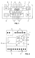
- a programmable electrical device 1 represented in FIG. 1 comprises a unit for processing 2, outputs 3 connected to the processing unit, inputs 4 connected to the processing unit, selection means 5 such as push button keys or a keyboard connected to the processing unit, display means 6 such as a display connected to the processing unit, storage means 7 associated with the processing unit, and a supply circuit 8 for supplying in particular the processing and display means.
- the processing unit includes an electronic circuit 9 to control relays 10 having output contacts connected to outputs 3.
- the processing unit includes allocation means for assigning to at least one output 3 at least one function selected from electrical switchgear functions predefined command and to assign to said electrical equipment function selected at least one operating parameter value selected from among predefined parameter values. For example if a function requires an input, a said function uses the state of said input to determine the state of said output.
- a function of electrical control equipment can be, in particular, a function clock, or a time switch function, or a flashing function, or a timer function, or timer relay function, or counter function, or a down counter function, Some functions can be triggered by a changes the state of an entry.
- One or more different predefined electrical control device functions can be assigned to an output.
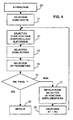
- Figure 2 shows a device according to Figure 1 arranged in a modular housing.
- the inlets 4 are arranged on the upper part and the outlets 3 are arranged on the part bottom of the case.
- a front face 11 of said housing comprises a display 6, of preferably of the liquid crystal type, and of the keys of the selection means 5.
- four keys 12 make it possible to control the scrolling of lists of predefined functions and parameters
- two keys 15 and 16 are used to control the change of predefined parameter values
- a key 13 is used to control display of an installation or programming menu
- a button 14 validates assigning functions of parameter values and / or changing values.
- the flow diagram of FIG. 3 includes a step 20 for selecting the display language and a step 21 for selecting the date and time. These first two steps can be necessary when the programmable electrical device is put into service for the first time. Then, a permanent display step 22 makes it possible to display, for example, the date and time or status of inputs and outputs according to the default permanent display mode or the display mode chosen in particular in a preliminary step.
- a step 24 of selecting actions makes it possible to display a menu for choosing actions, in particular following a command of key 13.
- a drop-down menu during the step 24 allows in particular to choose a date or time change step 25 which returns for example in step 21, a step 26 for permanently displaying the states of the inputs and / or outputs, a step 27 to display the details of the outputs.
- Step 26 it is possible to select an output and then display details of the associated functions at said exit.
- Step 24 also allows you to choose a step 28 to access a menu of installation and a phase 29 of allocation of functions to outputs according to a mode realization of the invention.
- step 24 can also steer towards a phase 30 of modification of parameters so as to modify directly parameter values that can be variable and freely accessible.
- FIG. 4 A flowchart of an allocation phase is shown in Figure 4.
- an output is selected in a step 31 of selecting an output.
- a function is assigned to said output.
- an entry is assigned to said function in step 33.
- a step 34 makes it possible to select parameters associated with the chosen function.
- a step 35 makes it possible to exit from assigning a function to an output to a step 36 of returning or returning to assigning a function to select an additional function at a step 37.
- a step 38 makes it possible to choose a logical operator between functions to control the selected output.
- Steps 36 and 37 are also validation and memorization steps making it possible to store in stores the functions assigned to the outputs.
- the operating ranges can be in particular daily, weekly and / or yearly.
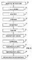
- a step 49 return to function selection allows you to exit this drop-down menu and go to a next menu which consists in selecting in particular an entry or parameters of operation. This step also allows you to validate or memorize the function assigned to the exit.
- Figure 6 shows a flowchart for selecting parameters for a timer function of a programmable electrical device.
- a menu makes it possible to choose an entry during a step 50.
- a menu allows you to choose a timeout value or a timeout value command of the selected output following a command on the selected input.
- a step 52 makes it possible to exit the timer function selection menu.
- FIG. 7 represents a flowchart for selecting parameters of a clock function or time switch of a programmable electric device.
- a menu allows you to choose an operating range during of a stage 53.
- One hour and one day of start and one hour and one day of end the actuation of an output are assigned to this operating range in a step 54.
- a step 55 makes it possible to repeat the hours of start and end over several days.
- a step 56 makes it possible to return to step 53 to define a new time range.
- a step 57 makes it possible to assign conditions for example the status of an input to control the selected output.
- a step 58 makes it possible to validate and exit the selection of the clock function.
- This phase allows direct access to modifiable parameters without going through the phase 29.
- modifiable parameters there can be the delay times time relays or timer functions, the time periods of the switches times, or the thresholds of counters or down counters.
- the device described above and shown in Figures 1 and 2 has four outputs and six inputs, however in other embodiments devices according to the invention of different numbers of inputs and outputs can be provided. Entries can be logic or analog.
- the outputs can also be three-terminal change-over contacts with a common, a rest contact and work contact.
- the device casing is preferably modular, but other casings can also suit.
- Some devices may also include a communication device for communicate with a remote central.
- a communication device for communicate with a remote central.
- the states of the outputs and inputs can be carried over as well as the assignments of functions and parameters.
Landscapes
- Physics & Mathematics (AREA)
- General Physics & Mathematics (AREA)
- Engineering & Computer Science (AREA)
- Automation & Control Theory (AREA)
- Programmable Controllers (AREA)
Abstract
Description
- une étape de sélection d'une sortie,
- une étape de sélection d'une première fonction d'appareillage électrique de commande à attribuer à ladite sortie, et
- une étape de validation ou de mémorisation.
- une étape de sélection d'une sortie,
- une étape de sélection d'une première fonction d'appareillage électrique à attribuer à ladite sortie, et
- une étape de validation ou de mémorisation.
- la figure 1 représente un schéma d'un dispositif électrique programmable ;
- la figure 2 représente un boítier modulaire comportant un dispositif électrique programmable ;
- la figure 3 représente un organigramme de fonctionnement d'un dispositif électrique programmable ;
- la figure 4 représente un premier organigramme d'attribution de fonctions d'un dispositif électrique programmable selon un mode de réalisation l'invention ;
- la figure 5 représente un second organigramme d'attribution de fonctions d'un dispositif électrique programmable selon un mode de réalisation l'invention ;
- la figure 6 représente un organigramme de sélection de paramètres d'une fonction minuterie d'un dispositif électrique programmable selon un mode de réalisation l'invention ;
- la figure 7 représente un organigramme de sélection de paramètres d'une horloge d'un dispositif électrique programmable selon un mode de réalisation l'invention.
- une étape 40 pour attribuer une fonction où la sortie est représentative de l'état d'une entrée ou de son inverse,
- une étape 41 pour attribuer une fonction minuterie pouvant être déclenchée par l'état ou le changement d'état d'une entrée,
- une étape 42 pour attribuer une fonction compteur pour compter des changements d'état d'une entrée et faire changer d'état d'une sortie si une valeur de seuil correspondant à un nombre prédéterminé est dépassée,
- une étape 43 pour attribuer une fonction décompteur pour décompter des changements d'état d'une entrée et faire changer d'état d'une sortie si une valeur de seuil correspondant à un nombre prédéterminé est atteinte,
- une étape 44 ou une étape 45 pour attribuer une fonction horloge ou une fonction interrupteur horaire pour commander une sortie en fonction d'au moins une plage horaire prédéterminée, pour certaines plages horaires ladite sortie sélectionnée pouvant aussi être dépendante de l'état d'une entrée,
- une étape 46 pour attribuer une fonction clignotant pour activer et désactiver une sortie en fonction d'un cycle et d'une période prédéterminés, ou
- une étape 47 ou une étape 48 pour attribuer une fonction temporisateur pouvant être déclenché à l'enclenchement ou au déclenchement d'une entrée pour retarder la commande d'une sortie sélectionnée. Une fonction temporisateur peut aussi être appelée fonction de relais temporisé.
Claims (10)
- Dispositif électrique programmable comportant :dispositif caractérisé en ce que l'unité de traitement (2) comporte des moyens (29, 31-34) d'attribution pour attribuer à au moins une sortie (3, 31) au moins une fonction (32) sélectionnée parmi des fonctions d'appareillage électrique de commande prédéfinies (40-49) et pour attribuer à ladite fonction d'appareillage électrique sélectionnée au moins une valeur de paramètres (34) de fonctionnement sélectionnée parmi des valeurs de paramètres prédéfinies.une unité de traitement (2),au moins une sortie (3) connectée à l'unité de traitement,des moyens (6) de visualisation connectés à l'unité de traitement,des moyens (5, 12-16) de sélection connectés à l'unité de traitement, etdes moyens (7) de mémorisation associés à l'unité de traitement,
- Dispositif selon la revendication 1 caractérisé en ce qu'il comporte au moins une entrée (4) connectée à l'unité de traitement (2), et en ce qu'au moins une sortie (3) est dépendante d'au moins une fonction (40-49) d'appareillage électrique de commande prédéfinie utilisant l'état de ladite au moins une entrée (4).
- Dispositif selon la revendication 2 caractérisé en ce qu'au moins une fonction d'appareillage électrique de commande (32, 40-49) est une fonction de minuterie (41), ou une fonction de relais temporisé (47, 48), ou une fonction de compteur (42), ou une fonction de décompteur (43) déclenché par un changement l'état de la dite entrée.
- Dispositif selon l'une quelconque des revendications 1 à 3 caractérisé en ce qu'au moins une fonction d'appareillage électrique de commande (32, 40-49) est une fonction d'horloge (44), ou une fonction d'interrupteur horaire (45) ou une fonction de clignotant (46).
- Dispositif selon l'une quelconque des revendications 1 à 4 caractérisé en ce que les moyens d'attribution (29, 31-35, 37, 38) permettent d'attribuer à une sortie (3) au moins deux fonctions d'appareillage électrique de commande prédéfinies différentes (40-48).
- Dispositif selon l'une quelconque des revendications 1 à 5 caractérisé en ce que les moyens de visualisation (6, 26, 27) ont un mode de fonctionnement affichant les états d'un ensemble de sorties (3).
- Procédé de sélection d'une phase d'attribution (29) d'une unité de traitement d'un dispositif selon l'une quelconque des revendications 1 à 6 caractérisé en ce qu'il comporte :une étape (31) de sélection d'une sortie (4),une étape (32) de sélection d'une première fonction d'appareillage électrique de commande (40-48) à attribuer à ladite sortie (4), etune étape (36, 37, 49, 58) de validation ou de mémorisation.
- Procédé selon la revendication 7 caractérisé en ce qu'il comporte une étape (34, 51, 54-57) de sélection de paramètres de fonctionnement de ladite première fonction.
- Procédé selon l'une des revendications 7 ou 8 caractérisé en ce qu'il comporte une étape (33, 50) de sélection d'une entrée à attribuer à ladite première fonction.
- Procédé selon l'une quelconque des revendications 7 à 9 caractérisé en ce qu'il comporte une étape (37, 38, 32) de sélection d'une seconde fonction d'appareillage électrique de commande à attribuer à ladite sortie.
Applications Claiming Priority (2)
| Application Number | Priority Date | Filing Date | Title |
|---|---|---|---|
| FR0014930A FR2817052B1 (fr) | 2000-11-20 | 2000-11-20 | Dispositif electrique programmable |
| FR0014930 | 2000-11-20 |
Publications (2)
| Publication Number | Publication Date |
|---|---|
| EP1207442A1 true EP1207442A1 (fr) | 2002-05-22 |
| EP1207442B1 EP1207442B1 (fr) | 2004-04-21 |
Family
ID=8856648
Family Applications (1)
| Application Number | Title | Priority Date | Filing Date |
|---|---|---|---|
| EP20010410153 Expired - Lifetime EP1207442B1 (fr) | 2000-11-20 | 2001-11-16 | Dispositif électrique programmable |
Country Status (5)
| Country | Link |
|---|---|
| EP (1) | EP1207442B1 (fr) |
| CN (1) | CN1241077C (fr) |
| DE (1) | DE60102886T2 (fr) |
| ES (1) | ES2217101T3 (fr) |
| FR (1) | FR2817052B1 (fr) |
Families Citing this family (2)
| Publication number | Priority date | Publication date | Assignee | Title |
|---|---|---|---|---|
| CN103904618A (zh) * | 2012-12-27 | 2014-07-02 | 施耐德电器工业公司 | 电机保护器及其编程和操作方法 |
| CN114690625A (zh) * | 2020-12-28 | 2022-07-01 | 直白科技(杭州)有限公司 | 一种自学习吹风机 |
Citations (4)
| Publication number | Priority date | Publication date | Assignee | Title |
|---|---|---|---|---|
| DE4212370A1 (de) * | 1992-04-13 | 1993-10-14 | Siemens Ag | Modell zur programmtechnischen Nachbildung einer verfahrenstechnischen Anlage mit einem "Wegenetz", Automatisierungsgerät zur Führung einer derartigen Anlage und bevorzugte Verwendung desselben |
| DE4410478A1 (de) * | 1994-03-25 | 1995-11-30 | Passtec Ind Elektronik Gmbh | Steuerschaltung für Verschließeinrichtungen mit integriertem Sicherheitssystem |
| DE19513230A1 (de) * | 1995-04-07 | 1996-10-10 | Siemens Ag | Programmiergerät |
| EP0899670A1 (fr) * | 1997-08-26 | 1999-03-03 | Boris Shapiro | Dispositif et procédé pour la conception et mise en oeuvre d'un processus de fabrication |
-
2000
- 2000-11-20 FR FR0014930A patent/FR2817052B1/fr not_active Expired - Fee Related
-
2001
- 2001-11-14 CN CN 01138479 patent/CN1241077C/zh not_active Expired - Fee Related
- 2001-11-16 EP EP20010410153 patent/EP1207442B1/fr not_active Expired - Lifetime
- 2001-11-16 ES ES01410153T patent/ES2217101T3/es not_active Expired - Lifetime
- 2001-11-16 DE DE2001602886 patent/DE60102886T2/de not_active Expired - Lifetime
Patent Citations (4)
| Publication number | Priority date | Publication date | Assignee | Title |
|---|---|---|---|---|
| DE4212370A1 (de) * | 1992-04-13 | 1993-10-14 | Siemens Ag | Modell zur programmtechnischen Nachbildung einer verfahrenstechnischen Anlage mit einem "Wegenetz", Automatisierungsgerät zur Führung einer derartigen Anlage und bevorzugte Verwendung desselben |
| DE4410478A1 (de) * | 1994-03-25 | 1995-11-30 | Passtec Ind Elektronik Gmbh | Steuerschaltung für Verschließeinrichtungen mit integriertem Sicherheitssystem |
| DE19513230A1 (de) * | 1995-04-07 | 1996-10-10 | Siemens Ag | Programmiergerät |
| EP0899670A1 (fr) * | 1997-08-26 | 1999-03-03 | Boris Shapiro | Dispositif et procédé pour la conception et mise en oeuvre d'un processus de fabrication |
Non-Patent Citations (1)
| Title |
|---|
| ZILKER M: "TABELLENGESTEUERTE ECHTZEITVERARBEITUNG", ELEKTRONIK, FRANZIS VERLAG GMBH. MUNCHEN, DE, vol. 38, no. 3, 3 February 1989 (1989-02-03), pages 56 - 58, XP000031870, ISSN: 0013-5658 * |
Also Published As
| Publication number | Publication date |
|---|---|
| CN1354403A (zh) | 2002-06-19 |
| CN1241077C (zh) | 2006-02-08 |
| ES2217101T3 (es) | 2004-11-01 |
| DE60102886T2 (de) | 2005-04-07 |
| DE60102886D1 (de) | 2004-05-27 |
| FR2817052B1 (fr) | 2003-02-07 |
| FR2817052A1 (fr) | 2002-05-24 |
| EP1207442B1 (fr) | 2004-04-21 |
Similar Documents
| Publication | Publication Date | Title |
|---|---|---|
| US12208686B2 (en) | Method for generating and outputting graphical info objects on a graphical user interface | |
| FR2805621A1 (fr) | Systeme, procede, bus, dispositif, module, arrangement et alimentation pour installation programmable d'eclairage | |
| EP0944218A1 (fr) | Appareil électronique comportant un écran et procédé pour afficher des graphismes | |
| GB2365712A (en) | Computing device able to display an application summary window comprising a limited list of common functions offered within that application and/or data | |
| WO2015045931A1 (fr) | Procédé d'adaptation d'une interface utilisateur d'un système de navigation dans un véhicule | |
| FR2703620A1 (fr) | Système de commande multitâche pour un robot. | |
| EP1207442B1 (fr) | Dispositif électrique programmable | |
| MXPA03004466A (es) | Unidad conmutadora. | |
| US20130080959A1 (en) | Simplified navigation among process control views in a process control system | |
| CN110568977A (zh) | 控制显示设备的方法、装置及计算机可读存储介质 | |
| US3931481A (en) | Plural line selector apparatus for enabling selection of one of a plurality of telephone lines | |
| EP0296022A1 (fr) | Dispositif d'adressage sur bus | |
| JP6939047B2 (ja) | 遊技機 | |
| CN1099542A (zh) | 自动百位判别电路 | |
| JP2019103134A (ja) | インターコムネットワーク用通話装置 | |
| JP2021142386A (ja) | 遊技機 | |
| US20040199274A1 (en) | Device for operation and observation, having a fast input keypad | |
| CN103338294A (zh) | 通信设备中基于显示模式的输入键功能再分配 | |
| EP0837537B1 (fr) | Dispositif de commande par télérupteur programmable | |
| CA2560201A1 (fr) | Systeme multimedia de vehicule et procede permettant d'activer une fonction d'un systeme multimedia de vehicule | |
| CN110688041B (zh) | 移动客户端焦点调整方法、装置、移动终端和可读存储介质 | |
| US7112894B2 (en) | Method, programming interface and mechanism for changing vehicle personalization settings/features | |
| KR20080064025A (ko) | 입체 인터페이스를 이용한 이동통신 단말기의 동작방법 | |
| WO2008003428A1 (fr) | Surveillance d'un réseau mstp | |
| EP3531215B1 (fr) | Procédé de fonctionnement d'un module de commande d'une charge électrique |
Legal Events
| Date | Code | Title | Description |
|---|---|---|---|
| PUAI | Public reference made under article 153(3) epc to a published international application that has entered the european phase |
Free format text: ORIGINAL CODE: 0009012 |
|
| AX | Request for extension of the european patent |
Free format text: AL;LT;LV;MK;RO;SI |
|
| RAP1 | Party data changed (applicant data changed or rights of an application transferred) |
Owner name: SCHNEIDER ELECTRIC INDUSTRIES SAS |
|
| 17P | Request for examination filed |
Effective date: 20020902 |
|
| AKX | Designation fees paid |
Designated state(s): DE ES GB IT NL |
|
| 17Q | First examination report despatched |
Effective date: 20030610 |
|
| GRAP | Despatch of communication of intention to grant a patent |
Free format text: ORIGINAL CODE: EPIDOSNIGR1 |
|
| GRAS | Grant fee paid |
Free format text: ORIGINAL CODE: EPIDOSNIGR3 |
|
| GRAA | (expected) grant |
Free format text: ORIGINAL CODE: 0009210 |
|
| AK | Designated contracting states |
Kind code of ref document: B1 Designated state(s): DE ES GB IT NL |
|
| REG | Reference to a national code |
Ref country code: GB Ref legal event code: FG4D Free format text: NOT ENGLISH |
|
| REG | Reference to a national code |
Ref country code: IE Ref legal event code: FG4D Free format text: FRENCH |
|
| REF | Corresponds to: |
Ref document number: 60102886 Country of ref document: DE Date of ref document: 20040527 Kind code of ref document: P |
|
| GBT | Gb: translation of ep patent filed (gb section 77(6)(a)/1977) |
Effective date: 20040608 |
|
| REG | Reference to a national code |
Ref country code: ES Ref legal event code: FG2A Ref document number: 2217101 Country of ref document: ES Kind code of ref document: T3 |
|
| REG | Reference to a national code |
Ref country code: IE Ref legal event code: FD4D |
|
| PLBE | No opposition filed within time limit |
Free format text: ORIGINAL CODE: 0009261 |
|
| STAA | Information on the status of an ep patent application or granted ep patent |
Free format text: STATUS: NO OPPOSITION FILED WITHIN TIME LIMIT |
|
| 26N | No opposition filed |
Effective date: 20050124 |
|
| PGFP | Annual fee paid to national office [announced via postgrant information from national office to epo] |
Ref country code: DE Payment date: 20151109 Year of fee payment: 15 Ref country code: GB Payment date: 20151111 Year of fee payment: 15 Ref country code: IT Payment date: 20151124 Year of fee payment: 15 |
|
| PGFP | Annual fee paid to national office [announced via postgrant information from national office to epo] |
Ref country code: ES Payment date: 20151014 Year of fee payment: 15 Ref country code: NL Payment date: 20151110 Year of fee payment: 15 |
|
| REG | Reference to a national code |
Ref country code: DE Ref legal event code: R119 Ref document number: 60102886 Country of ref document: DE |
|
| REG | Reference to a national code |
Ref country code: NL Ref legal event code: MM Effective date: 20161201 |
|
| GBPC | Gb: european patent ceased through non-payment of renewal fee |
Effective date: 20161116 |
|
| PG25 | Lapsed in a contracting state [announced via postgrant information from national office to epo] |
Ref country code: NL Free format text: LAPSE BECAUSE OF NON-PAYMENT OF DUE FEES Effective date: 20161201 |
|
| PG25 | Lapsed in a contracting state [announced via postgrant information from national office to epo] |
Ref country code: IT Free format text: LAPSE BECAUSE OF NON-PAYMENT OF DUE FEES Effective date: 20161116 |
|
| PG25 | Lapsed in a contracting state [announced via postgrant information from national office to epo] |
Ref country code: DE Free format text: LAPSE BECAUSE OF NON-PAYMENT OF DUE FEES Effective date: 20170601 Ref country code: GB Free format text: LAPSE BECAUSE OF NON-PAYMENT OF DUE FEES Effective date: 20161116 |
|
| PG25 | Lapsed in a contracting state [announced via postgrant information from national office to epo] |
Ref country code: ES Free format text: LAPSE BECAUSE OF FAILURE TO SUBMIT A TRANSLATION OF THE DESCRIPTION OR TO PAY THE FEE WITHIN THE PRESCRIBED TIME-LIMIT Effective date: 20040421 |
|
| REG | Reference to a national code |
Ref country code: ES Ref legal event code: FD2A Effective date: 20181119 |
|
| PG25 | Lapsed in a contracting state [announced via postgrant information from national office to epo] |
Ref country code: ES Free format text: LAPSE BECAUSE OF FAILURE TO SUBMIT A TRANSLATION OF THE DESCRIPTION OR TO PAY THE FEE WITHIN THE PRESCRIBED TIME-LIMIT Effective date: 20161117 |