EP1207375B1 - Arrangement de tubes pour un débimètre à effet Coriolis - Google Patents
Arrangement de tubes pour un débimètre à effet Coriolis Download PDFInfo
- Publication number
- EP1207375B1 EP1207375B1 EP00125054A EP00125054A EP1207375B1 EP 1207375 B1 EP1207375 B1 EP 1207375B1 EP 00125054 A EP00125054 A EP 00125054A EP 00125054 A EP00125054 A EP 00125054A EP 1207375 B1 EP1207375 B1 EP 1207375B1
- Authority
- EP
- European Patent Office
- Prior art keywords
- tube
- elbow
- inlet
- resonant frequency
- mass
- Prior art date
- Legal status (The legal status is an assumption and is not a legal conclusion. Google has not performed a legal analysis and makes no representation as to the accuracy of the status listed.)
- Expired - Lifetime
Links
Images

Classifications
-
- G—PHYSICS
- G01—MEASURING; TESTING
- G01F—MEASURING VOLUME, VOLUME FLOW, MASS FLOW OR LIQUID LEVEL; METERING BY VOLUME
- G01F1/00—Measuring the volume flow or mass flow of fluid or fluent solid material wherein the fluid passes through a meter in a continuous flow
- G01F1/76—Devices for measuring mass flow of a fluid or a fluent solid material
- G01F1/78—Direct mass flowmeters
- G01F1/80—Direct mass flowmeters operating by measuring pressure, force, momentum, or frequency of a fluid flow to which a rotational movement has been imparted
- G01F1/84—Coriolis or gyroscopic mass flowmeters
- G01F1/8409—Coriolis or gyroscopic mass flowmeters constructional details
- G01F1/8413—Coriolis or gyroscopic mass flowmeters constructional details means for influencing the flowmeter's motional or vibrational behaviour, e.g., conduit support or fixing means, or conduit attachments
- G01F1/8418—Coriolis or gyroscopic mass flowmeters constructional details means for influencing the flowmeter's motional or vibrational behaviour, e.g., conduit support or fixing means, or conduit attachments motion or vibration balancing means
-
- G—PHYSICS
- G01—MEASURING; TESTING
- G01F—MEASURING VOLUME, VOLUME FLOW, MASS FLOW OR LIQUID LEVEL; METERING BY VOLUME
- G01F1/00—Measuring the volume flow or mass flow of fluid or fluent solid material wherein the fluid passes through a meter in a continuous flow
- G01F1/76—Devices for measuring mass flow of a fluid or a fluent solid material
- G01F1/78—Direct mass flowmeters
- G01F1/80—Direct mass flowmeters operating by measuring pressure, force, momentum, or frequency of a fluid flow to which a rotational movement has been imparted
- G01F1/84—Coriolis or gyroscopic mass flowmeters
- G01F1/845—Coriolis or gyroscopic mass flowmeters arrangements of measuring means, e.g., of measuring conduits
- G01F1/8468—Coriolis or gyroscopic mass flowmeters arrangements of measuring means, e.g., of measuring conduits vibrating measuring conduits
- G01F1/8472—Coriolis or gyroscopic mass flowmeters arrangements of measuring means, e.g., of measuring conduits vibrating measuring conduits having curved measuring conduits, i.e. whereby the measuring conduits' curved center line lies within a plane
Definitions
- the invention relates to a tube assembly belonging to a mass flow / density / viscosity meter operating on the Coriolis principle. This is referred to below as the Coriolis flowmeter.
- Such Coriolis flowmeters are used to measure the mass flow and / or the density and / or the viscosity of a fluid flowing at least temporarily in a pipeline; the Coriolis flowmeter is inserted into the tubing for this purpose, e.g. attached pressure-tight by means of flanges.
- the inventors have therefore set themselves the goal of the transducer with straight measuring tube according to US-A 60 06 609 ago her known, the two bending vibration basic modes and the two Meßrohr resonance frequencies conditional principle of the cantilever body provided with curved in a plane measuring tube Coriolis To make available flow sensors.
- the tube is bent in a V-shape.
- a first major advantage of the invention is that it enables Coriolis mass flow / density / viscosity transducers to be bent into a flat, single measuring tube, which is virtually immune to both external disturbing frequencies as well as emitting little vibrational energy to the outside that the transducer has a reasonable energy intake.
- Another advantage is that the length of the transducer so the length along the inlet / outlet axis, compared to the length of the prescribed arrangement according to WO-A 99/51946, is substantially shorter. This is among others on the Attributed V-shape of the measuring tube. Overall, therefore, there is a Kompaktaufsacrificing, which also has the measurement accuracy of about 0.5% required by the market today.
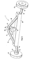
- the tube assembly 1 is an integral part of a Coriolis Masse pressfluß- / density / viscosity meter, which is inserted into a fluid at least temporarily flowed through a pipeline axis having pipe; serve this purpose in the embodiment flanges 21, 22 which are fixed to the pipe assembly 1, esp. So brazed or welded.
- the tube assembly 1 itself has a single, in a plane with respect to a symmetry line 2 symmetrically bent, one-piece tube, which preferably has a V-shape.
- the tube comprises a straight, opening in a first connector 11 inlet piece 13, which has an in-plane inlet axis.
- the symmetry line 2 is in Fig. 1 perpendicular to the inlet axis.
- the pipe includes a straight, opening in a second connector 12 outlet piece 14, which also has an in-plane and aligned with the inlet axis outlet.
- a second connector 12 outlet piece 14 which also has an in-plane and aligned with the inlet axis outlet.
- the pipe further comprises an inlet bend 15, an outlet bend 16, a crown arch 19, a straight first leg tube 17 connecting the inlet bend 15 to the crown arch 19, and a straight second leg tube 18 joining the outlet bend 16 to the crown arch 19.
- the first leg tube piece 17 and the second leg tube piece 18 are passed through a rigid support body 20 and fixed therein for fixing an oscillatable measuring tube 10; this is indicated by a respective fixing point 31, 32 in Fig. 1.
- the fixation is esp. By brazing or welding.
- the measuring tube 10 is thus limited by the fixing points 31, 32 in the carrier body 20.
- the measuring tube 10 is thus formed by a part of the leg tube piece 17, the apex arch 19 and a part of the leg tube piece 18, is capable of oscillation and thus forms a first oscillating system, as is the case for the Function of a Coriolis mass flow / density / viscosity meter is required.
- the support body 20 is a straight body of rectangular cross-section, and it is lying in the vicinity of the inlet arc 15 parts of the first leg tube piece 17 and to the opposite lying in the vicinity of the outlet arc 16 parts of the second leg tube piece 18 passed through the carrier body 20 and fixed therein.
- the mass of the carrier body 20 is at least ten times to 50 times as large as the mass of the empty measuring tube 10.
- the carrier body 20 consists esp. Of solid material, but of course inclined bores for the measuring tube 10. It is also possible, a cuboid tube, a Profile body with similar vibration characteristics or a composite of individual plates body as a carrier body 20 to use.
- the tube assembly 1 further comprises a first cantilever body 91 which is fixed symmetrically to the plane in the center of the apex arch 19 by means of a first spring body 92.
- the mass of the cantilever body 91 is to be selected in the order of the mass of the empty measuring tube 10; this includes that this mass may also be smaller than the mass of the empty measuring tube 10, esp. It may be one third to one fifth smaller.
- the cantilever body 91 is esp. Formed as a cuboid.
- the cantilever body 91 requires that the measuring tube 10 can oscillate either in a first fundamental vibration mode with a first measuring tube resonant frequency or in a second fundamental vibration mode with higher frequency than the first fundamental vibration mode with a second measuring tube resonant frequency.
- the Coriolis mass flow / density / viscosity meter ensure that only the second fundamental vibration mode occurs.
- Inlet piece 13, inlet sheet 15, support body 20, outlet bend 16 and outlet piece 14 form, in addition to the first oscillating system of the oscillatable measuring tube 10, a second oscillating system; it has, by itself, a resonance frequency which is to be dimensioned such that it is at most equal to 0.5 times the second measuring tube resonant frequency of the measuring tube 10 filled with water.
- the first spring body 92 has a spring stiffness dimensioned such that a third oscillating system formed by the cantilever body 91 and the spring body 92 has, by itself, a resonant frequency which, when the measuring tube is filled with water, is approximately equal to 0.8 times the second measuring tube resonant frequency is.
- the spring body 92 is esp. Formed as a leaf spring.
- a second cantilever body 93 is fixed symmetrically to the plane on the carrier body 20 relative to the apex arch 19 by means of a second spring body 94.
- the mass of the second cantilever body 93 is at least ten times as large as the mass of the empty measuring tube 10 to choose.
- the boom body 93 is esp. Formed as a cuboid.
- the second spring body 94 has such a dimensioned spring stiffness that a cantilever body 93 and spring body 94 formed fourth vibration system - by itself Considered - has a resonant frequency, which is approximately equal to the second measuring tube resonant frequency when filled with water measuring tube.
- the spring body 94 is esp. Again designed as a leaf spring.
- the mass of the measuring tube 10 was four times as large as the mass of the cantilever body 91 and the mass of the cantilever body 93 was 40 times as large as the mass of the cantilever body 91.
- the second oscillating system inlet piece 13, inlet sheet 15, carrier piece 20, outlet sheet 16 and outlet piece 14
- the second oscillating system also oscillates at this frequency.
- the cantilever bodies 91, 93 respectively move in opposite phase to the measuring tube 10.
- a combination of lateral and rotational movement occurs at the fixing points 31, 32 of the measuring tube 10 in the carrier body 20, which extends to the flanges 21, 22 down to a minimum.
Landscapes
- Physics & Mathematics (AREA)
- Fluid Mechanics (AREA)
- General Physics & Mathematics (AREA)
- Measuring Volume Flow (AREA)
- Rigid Pipes And Flexible Pipes (AREA)
Claims (2)
- Disposition de tubes (1) d'un débitmètre Coriolis -densitomètre - viscosimètre qui est introduit dans un tube comportant un axe de tube et traversé au moins temporairement par un fluide, laquelle disposition (1) comporte :- un seul tube monobloc courbé dans un plan de façon symétrique par rapport à une ligne de symétrie (2), lequel tube est constitué de :■ une pièce d'entrée (13) droite débouchant dans une première pièce de connexion (11), laquelle pièce d'entrée présente un axe d'entrée situé dans un plan,■ une pièce de sortie (14) droite débouchant dans une deuxième pièce de connexion (12), laquelle pièce de sortie présente un axe de sortie aligné avec l'axe d'entrée,■ un coude d'entrée (15),■ un coude de sortie (16),■ un coude d'apex (19),■ une première branche de pièce tubulaire (17) droite connectant le coude d'entrée (15) avec le coude d'apex (19),■ une deuxième branche de pièce tubulaire (18) droite connectant le coude de sortie (16) avec le coude d'apex (19),--- laquelle première branche de pièce tubulaire (17) et laquelle deuxième branche de pièce tubulaire (18) sont guidées à travers un corps de support rigide (20) et fixées sur ce corps pour immobiliser un tube de mesure (10) formant un premier système oscillant ; le tube de mesure (10) étant formé par une partie de la première branche de pièce tubulaire (17), du coude d'apex (19) et d'une partie de la deuxième branche de pièce tubulaire (18),--- la masse du corps de support (20) étant au moins 10 à 50 fois plus importante que la masse du tube de mesure (10) vide,--- un premier corps cantilever (91),■ qui est fixé de façon symétrique par rapport au plan au moyen d'un premier corps de ressort (92) au milieu du coude apex (19),■ la masse dudit corps cantilever ayant un ordre de grandeur correspondant à la masse du tube de mesure (10) vide et,■ ledit corps cantilever entraînant une oscillation du tube de mesure, soit dans un premier mode de base d'oscillation avec une première fréquence de résonance du tube de mesure, ou dans un deuxième mode de base d'oscillation avec une deuxième fréquence de résonance du tube de mesure présentant une fréquence supérieure premier mode de base d'oscillation,■ où seul le deuxième mode de base d'oscillation apparaît pendant le service et,■ la pièce d'entrée (13), le coude d'entrée (15), le corps de support (20), le coude de sortie (16) et la pièce de sortie (14) formant un deuxième système d'oscillation, dont la fréquence de résonance est au moins égale à 0,5 fois la deuxième fréquence de résonance du tube de mesure (10) rempli d'eau,■ le premier corps de ressort (92) présentant une rigidité de ressort de manière à ce qu'un troisième système d'oscillation formé par le premier corps cantilever (91) et le premier corps de ressort (92) ait une fréquence de résonance qui, pour un tube de mesure rempli d'eau, soit au moins égale à 0,8 fois la deuxième fréquence de résonance du tube de mesure, et- un deuxième corps cantilever (93),■ qui est fixé de façon symétrique par rapport au plan sur le corps de support (20) opposé au coude apex (19) au moyen d'un deuxième corps de ressort (94), et■ dont la masse est au moins dix fois supérieure à la masse du premier corps de ressort (91),■ le deuxième corps de ressort (94) présentant une rigidité de ressort de manière à ce qu'un quatrième système d'oscillation formé par le deuxième corps cantilever (93) et le deuxième corps de ressort (94) ait une fréquence de résonance qui, pour un tube de mesure rempli d'eau, soit au moins égale à la deuxième fréquence de résonance du tube de mesure.
- Disposition selon la revendication 1, dans laquelle le tube est plié selon la forme d'un V.
Priority Applications (3)
| Application Number | Priority Date | Filing Date | Title |
|---|---|---|---|
| DE50013132T DE50013132D1 (de) | 2000-11-16 | 2000-11-16 | Rohranordnung für einen Coriolis-Durchflussmesser |
| EP00125054A EP1207375B1 (fr) | 2000-11-16 | 2000-11-16 | Arrangement de tubes pour un débimètre à effet Coriolis |
| AT00125054T ATE332489T1 (de) | 2000-11-16 | 2000-11-16 | Rohranordnung für einen coriolis-durchflussmesser |
Applications Claiming Priority (1)
| Application Number | Priority Date | Filing Date | Title |
|---|---|---|---|
| EP00125054A EP1207375B1 (fr) | 2000-11-16 | 2000-11-16 | Arrangement de tubes pour un débimètre à effet Coriolis |
Publications (2)
| Publication Number | Publication Date |
|---|---|
| EP1207375A1 EP1207375A1 (fr) | 2002-05-22 |
| EP1207375B1 true EP1207375B1 (fr) | 2006-07-05 |
Family
ID=8170403
Family Applications (1)
| Application Number | Title | Priority Date | Filing Date |
|---|---|---|---|
| EP00125054A Expired - Lifetime EP1207375B1 (fr) | 2000-11-16 | 2000-11-16 | Arrangement de tubes pour un débimètre à effet Coriolis |
Country Status (3)
| Country | Link |
|---|---|
| EP (1) | EP1207375B1 (fr) |
| AT (1) | ATE332489T1 (fr) |
| DE (1) | DE50013132D1 (fr) |
Families Citing this family (6)
| Publication number | Priority date | Publication date | Assignee | Title |
|---|---|---|---|---|
| US7077014B2 (en) | 2004-06-23 | 2006-07-18 | Endress + Hauser Flowtec Ag | Vibration-type measuring transducer |
| US7631561B2 (en) | 2006-03-22 | 2009-12-15 | Endress + Hauser Flowtec Ag | Measuring transducer of vibration-type |
| US7555962B2 (en) | 2006-03-22 | 2009-07-07 | Endress + Hauser Flowtec Ag | Measuring transducer of vibration-type |
| US7546777B2 (en) | 2006-03-22 | 2009-06-16 | Endress + Hauser Flowtec Ag | Measuring transducer of vibration-type |
| DE102006013601A1 (de) | 2006-03-22 | 2007-09-27 | Endress + Hauser Flowtec Ag | Meßaufnehmer vom Vibrationstyp |
| US7921737B2 (en) * | 2008-02-11 | 2011-04-12 | Integrated Sensing Systems, Inc. | Microfluidic device and method of operation |
Family Cites Families (5)
| Publication number | Priority date | Publication date | Assignee | Title |
|---|---|---|---|---|
| US5373745A (en) * | 1991-02-05 | 1994-12-20 | Direct Measurement Corporation | Single path radial mode Coriolis mass flow rate meter |
| US5275061A (en) * | 1991-05-13 | 1994-01-04 | Exac Corporation | Coriolis mass flowmeter |
| DE4124295A1 (de) * | 1991-07-22 | 1993-01-28 | Krohne Ag | Massendurchflussmessgeraet |
| EP0601256B1 (fr) * | 1992-11-18 | 1995-03-08 | Endress + Hauser Flowtec AG | Débimètre massique selon le principe de Coriolis |
| ES2139985T3 (es) * | 1995-10-26 | 2000-02-16 | Flowtec Ag | Sensor de caudal segun el principio de coriolis con un solo tubo de medida. |
-
2000
- 2000-11-16 AT AT00125054T patent/ATE332489T1/de not_active IP Right Cessation
- 2000-11-16 DE DE50013132T patent/DE50013132D1/de not_active Expired - Fee Related
- 2000-11-16 EP EP00125054A patent/EP1207375B1/fr not_active Expired - Lifetime
Also Published As
| Publication number | Publication date |
|---|---|
| DE50013132D1 (de) | 2006-08-17 |
| EP1207375A1 (fr) | 2002-05-22 |
| ATE332489T1 (de) | 2006-07-15 |
Similar Documents
| Publication | Publication Date | Title |
|---|---|---|
| DE19621365C2 (de) | Massendurchflußmeßgerät | |
| EP0398103B1 (fr) | Dispositif de mesure du débit masse | |
| EP1502085B1 (fr) | Transformateur de mesure de type a vibrations | |
| EP1759178B1 (fr) | Transducteur du type transducteur de vibrations | |
| DE102008039867B4 (de) | Massedurchflußmeßgerät | |
| EP1229310B1 (fr) | Débitmètre massique à effet Coriolis avec un seul tuyau de mesure | |
| EP0547455A1 (fr) | Débitmètre de masse | |
| EP2304393B1 (fr) | Transducteur de mesure du type à vibration | |
| EP1253408A1 (fr) | Transducteur de mesure du type vibrant | |
| EP4302066A1 (fr) | Dispositif de mesure modulaire pour la détermination de la densité d'un milieu de mesure | |
| WO2016202537A1 (fr) | Débitmètre massique ou densimètre coriolis | |
| EP1207375B1 (fr) | Arrangement de tubes pour un débimètre à effet Coriolis | |
| DE102005062007A1 (de) | Meßwandler vom Vibrationstyp | |
| EP2201337B1 (fr) | Transducteur de vibrations | |
| DE102009002942A1 (de) | Verfahren zum Bestimmen einer Messrohr-Rohrwanddicke eines Coriolis-Durchflussmessgerätes | |
| WO2007074015A1 (fr) | Convertisseur de mesure du type a vibrations | |
| DE102009046043A1 (de) | Messwandler vom Vibrationstyp | |
| DE102005062004A1 (de) | Meßwandler vom Vibrationstyp | |
| DE10235322A1 (de) | Meßwandler vom Vibrationstyp | |
| EP0871017B1 (fr) | Débitmètre massique Coriolis avec un tube de mesure | |
| DE102016125615A1 (de) | Messaufnehmer vom Vibrationstyp zum Messen der Dichte und/oder des Massedurchflusses eines Mediums | |
| EP1949048B1 (fr) | Convertisseur de mesure du type a vibrations | |
| DE102004060115A1 (de) | Meßaufnehmer vom Vibrationstyp | |
| EP3732448B1 (fr) | Instrument de mesure du type à vibrations muni d'un tube de mesure | |
| EP1223412B1 (fr) | Débitmètre massique de Coriolis monotubulaire courbé avec dispositif d'excitation symétrique |
Legal Events
| Date | Code | Title | Description |
|---|---|---|---|
| PUAI | Public reference made under article 153(3) epc to a published international application that has entered the european phase |
Free format text: ORIGINAL CODE: 0009012 |
|
| AX | Request for extension of the european patent |
Free format text: AL;LT;LV;MK;RO;SI |
|
| 17P | Request for examination filed |
Effective date: 20021120 |
|
| AKX | Designation fees paid |
Designated state(s): AT BE CH CY DE DK ES FI FR GB GR IE IT LI LU MC NL PT SE TR |
|
| RTI1 | Title (correction) |
Free format text: TUBE ARRANGEMENT FOR A CORIOLIS FLOWMETER |
|
| GRAP | Despatch of communication of intention to grant a patent |
Free format text: ORIGINAL CODE: EPIDOSNIGR1 |
|
| GRAS | Grant fee paid |
Free format text: ORIGINAL CODE: EPIDOSNIGR3 |
|
| GRAA | (expected) grant |
Free format text: ORIGINAL CODE: 0009210 |
|
| AK | Designated contracting states |
Kind code of ref document: B1 Designated state(s): AT BE CH CY DE DK ES FI FR GB GR IE IT LI LU MC NL PT SE TR |
|
| PG25 | Lapsed in a contracting state [announced via postgrant information from national office to epo] |
Ref country code: IT Free format text: LAPSE BECAUSE OF FAILURE TO SUBMIT A TRANSLATION OF THE DESCRIPTION OR TO PAY THE FEE WITHIN THE PRESCRIBED TIME-LIMIT;WARNING: LAPSES OF ITALIAN PATENTS WITH EFFECTIVE DATE BEFORE 2007 MAY HAVE OCCURRED AT ANY TIME BEFORE 2007. THE CORRECT EFFECTIVE DATE MAY BE DIFFERENT FROM THE ONE RECORDED. Effective date: 20060705 Ref country code: FI Free format text: LAPSE BECAUSE OF FAILURE TO SUBMIT A TRANSLATION OF THE DESCRIPTION OR TO PAY THE FEE WITHIN THE PRESCRIBED TIME-LIMIT Effective date: 20060705 Ref country code: NL Free format text: LAPSE BECAUSE OF FAILURE TO SUBMIT A TRANSLATION OF THE DESCRIPTION OR TO PAY THE FEE WITHIN THE PRESCRIBED TIME-LIMIT Effective date: 20060705 Ref country code: GB Free format text: LAPSE BECAUSE OF FAILURE TO SUBMIT A TRANSLATION OF THE DESCRIPTION OR TO PAY THE FEE WITHIN THE PRESCRIBED TIME-LIMIT Effective date: 20060705 Ref country code: IE Free format text: LAPSE BECAUSE OF FAILURE TO SUBMIT A TRANSLATION OF THE DESCRIPTION OR TO PAY THE FEE WITHIN THE PRESCRIBED TIME-LIMIT Effective date: 20060705 |
|
| REG | Reference to a national code |
Ref country code: GB Ref legal event code: FG4D Free format text: NOT ENGLISH |
|
| REG | Reference to a national code |
Ref country code: CH Ref legal event code: EP |
|
| REG | Reference to a national code |
Ref country code: IE Ref legal event code: FG4D Free format text: LANGUAGE OF EP DOCUMENT: GERMAN |
|
| REF | Corresponds to: |
Ref document number: 50013132 Country of ref document: DE Date of ref document: 20060817 Kind code of ref document: P |
|
| PG25 | Lapsed in a contracting state [announced via postgrant information from national office to epo] |
Ref country code: DK Free format text: LAPSE BECAUSE OF FAILURE TO SUBMIT A TRANSLATION OF THE DESCRIPTION OR TO PAY THE FEE WITHIN THE PRESCRIBED TIME-LIMIT Effective date: 20061005 Ref country code: SE Free format text: LAPSE BECAUSE OF FAILURE TO SUBMIT A TRANSLATION OF THE DESCRIPTION OR TO PAY THE FEE WITHIN THE PRESCRIBED TIME-LIMIT Effective date: 20061005 |
|
| PG25 | Lapsed in a contracting state [announced via postgrant information from national office to epo] |
Ref country code: ES Free format text: LAPSE BECAUSE OF FAILURE TO SUBMIT A TRANSLATION OF THE DESCRIPTION OR TO PAY THE FEE WITHIN THE PRESCRIBED TIME-LIMIT Effective date: 20061016 |
|
| PG25 | Lapsed in a contracting state [announced via postgrant information from national office to epo] |
Ref country code: MC Free format text: LAPSE BECAUSE OF NON-PAYMENT OF DUE FEES Effective date: 20061130 Ref country code: LI Free format text: LAPSE BECAUSE OF NON-PAYMENT OF DUE FEES Effective date: 20061130 Ref country code: CH Free format text: LAPSE BECAUSE OF NON-PAYMENT OF DUE FEES Effective date: 20061130 Ref country code: BE Free format text: LAPSE BECAUSE OF NON-PAYMENT OF DUE FEES Effective date: 20061130 |
|
| NLV1 | Nl: lapsed or annulled due to failure to fulfill the requirements of art. 29p and 29m of the patents act | ||
| PG25 | Lapsed in a contracting state [announced via postgrant information from national office to epo] |
Ref country code: PT Free format text: LAPSE BECAUSE OF FAILURE TO SUBMIT A TRANSLATION OF THE DESCRIPTION OR TO PAY THE FEE WITHIN THE PRESCRIBED TIME-LIMIT Effective date: 20061205 |
|
| GBV | Gb: ep patent (uk) treated as always having been void in accordance with gb section 77(7)/1977 [no translation filed] |
Effective date: 20060705 |
|
| REG | Reference to a national code |
Ref country code: IE Ref legal event code: FD4D |
|
| EN | Fr: translation not filed | ||
| PLBE | No opposition filed within time limit |
Free format text: ORIGINAL CODE: 0009261 |
|
| STAA | Information on the status of an ep patent application or granted ep patent |
Free format text: STATUS: NO OPPOSITION FILED WITHIN TIME LIMIT |
|
| 26N | No opposition filed |
Effective date: 20070410 |
|
| REG | Reference to a national code |
Ref country code: CH Ref legal event code: PL |
|
| BERE | Be: lapsed |
Owner name: ENDRESS + HAUSER FLOWTEC A.G. Effective date: 20061130 |
|
| PG25 | Lapsed in a contracting state [announced via postgrant information from national office to epo] |
Ref country code: AT Free format text: LAPSE BECAUSE OF NON-PAYMENT OF DUE FEES Effective date: 20061116 |
|
| PG25 | Lapsed in a contracting state [announced via postgrant information from national office to epo] |
Ref country code: FR Free format text: LAPSE BECAUSE OF FAILURE TO SUBMIT A TRANSLATION OF THE DESCRIPTION OR TO PAY THE FEE WITHIN THE PRESCRIBED TIME-LIMIT Effective date: 20070511 Ref country code: GR Free format text: LAPSE BECAUSE OF FAILURE TO SUBMIT A TRANSLATION OF THE DESCRIPTION OR TO PAY THE FEE WITHIN THE PRESCRIBED TIME-LIMIT Effective date: 20061006 |
|
| PG25 | Lapsed in a contracting state [announced via postgrant information from national office to epo] |
Ref country code: LU Free format text: LAPSE BECAUSE OF NON-PAYMENT OF DUE FEES Effective date: 20061116 Ref country code: TR Free format text: LAPSE BECAUSE OF FAILURE TO SUBMIT A TRANSLATION OF THE DESCRIPTION OR TO PAY THE FEE WITHIN THE PRESCRIBED TIME-LIMIT Effective date: 20060705 |
|
| PG25 | Lapsed in a contracting state [announced via postgrant information from national office to epo] |
Ref country code: FR Free format text: LAPSE BECAUSE OF FAILURE TO SUBMIT A TRANSLATION OF THE DESCRIPTION OR TO PAY THE FEE WITHIN THE PRESCRIBED TIME-LIMIT Effective date: 20060705 Ref country code: CY Free format text: LAPSE BECAUSE OF FAILURE TO SUBMIT A TRANSLATION OF THE DESCRIPTION OR TO PAY THE FEE WITHIN THE PRESCRIBED TIME-LIMIT Effective date: 20060705 |
|
| PGFP | Annual fee paid to national office [announced via postgrant information from national office to epo] |
Ref country code: DE Payment date: 20081121 Year of fee payment: 9 |
|
| PG25 | Lapsed in a contracting state [announced via postgrant information from national office to epo] |
Ref country code: DE Free format text: LAPSE BECAUSE OF NON-PAYMENT OF DUE FEES Effective date: 20100601 |