EP1207368A2 - Verfahren zum Messen des Dickenprofils einer röhrenförmigen, dünnen Folie - Google Patents
Verfahren zum Messen des Dickenprofils einer röhrenförmigen, dünnen Folie Download PDFInfo
- Publication number
- EP1207368A2 EP1207368A2 EP01127092A EP01127092A EP1207368A2 EP 1207368 A2 EP1207368 A2 EP 1207368A2 EP 01127092 A EP01127092 A EP 01127092A EP 01127092 A EP01127092 A EP 01127092A EP 1207368 A2 EP1207368 A2 EP 1207368A2
- Authority
- EP
- European Patent Office
- Prior art keywords
- thickness
- tubular film
- longitudinal strips
- film
- axis
- Prior art date
- Legal status (The legal status is an assumption and is not a legal conclusion. Google has not performed a legal analysis and makes no representation as to the accuracy of the status listed.)
- Granted
Links
Images
Classifications
-
- G—PHYSICS
- G01—MEASURING; TESTING
- G01B—MEASURING LENGTH, THICKNESS OR SIMILAR LINEAR DIMENSIONS; MEASURING ANGLES; MEASURING AREAS; MEASURING IRREGULARITIES OF SURFACES OR CONTOURS
- G01B21/00—Measuring arrangements or details thereof, where the measuring technique is not covered by the other groups of this subclass, unspecified or not relevant
- G01B21/02—Measuring arrangements or details thereof, where the measuring technique is not covered by the other groups of this subclass, unspecified or not relevant for measuring length, width, or thickness
- G01B21/08—Measuring arrangements or details thereof, where the measuring technique is not covered by the other groups of this subclass, unspecified or not relevant for measuring length, width, or thickness for measuring thickness
Definitions
- the object of the present invention is a method for measuring the thickness profile of a flattened tubular film.
- the extruded tubular film after having been inflated, is passed through a drawing and flattening device, also known as a castle, in order to obtain a flattened tubular film, that is two superimposed layers of film joined at the edges.
- a drawing and flattening device also known as a castle
- the flattened tubular film is then taken towards a cutting station to be cut at the edges, so as to separate the two superimposed layers of film, obtaining two flat films, with a width substantially equal to half the circumference of the extruded tubular film, which are wound onto reels.
- the castle rotates alternately according to a vertical axis; consequently the axis of flattening of the tubular film varies continuously and so the errors in planarity of the film are uniformly distributed on the collecting reels.
- the thickness profile of the extruded tubular film is kept under control and so action is taken locally on the die of the extruder.
- a scanning head located before the cutting station, measures the thickness of the flattened tubular film.
- the tubular film is ideally divided into a plurality of longitudinal strips or sectors, familiarly known as "die bolts", all of the same width, each one corresponding to a sector of the extruder die.
- a thickness measuring device preferably of a type without contact, is located between the drawing and flattening station and the cutting station and moves with an alternate linear movement, in a direction transverse to the direction of advance movement of the flattened tubular film, between a first position, to which corresponds a first edge of the flattened tubular film, and a second position, to which corresponds a second edge, opposite the first edge, of the flattened tubular film.
- the measuring spot is at less than half the width of the longitudinal strips and the measuring head is synchronised with the rotation of the flattened tubular film, so that in the point corresponding to the opposite edges the reading is taken on two overlapping layers of the same longitudinal strip.
- the various longitudinal strips are taken, in sequence, to the area corresponding to the side edges and their thickness can be measured.
- the thickness measurements taken during the movement from one edge to the other may be used to estimate (dividing by two) the thicknesses of the overlapped longitudinal strips in the flattened tubular film.
- the thickness measurement is precise only on the end longitudinal strips, while on the intermediate longitudinal strips simply an estimate of the thickness is obtained, which is completely inadequate for the purposes of the control and regulation of the thickness profile of the tubular film.
- the measuring head To obtain a reliable measurement it is also necessary for the measuring head to remain for sufficient time on each longitudinal strip, avoiding distortion of the measurement by measuring noise (for example with a ⁇ ray sensor it must remain for a time of about 0.5 seconds).
- the measuring device does not manage to reach the opposite edge in time to measure another folded longitudinal strip; in this case synchronism is lost and the time taken to obtain the thickness profile is doubled.
- the reliability of measurement may be drastically decreased.
- the aim of the present invention is to find a solution to the problems mentioned above.
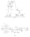
- figure 1 shows, schematically, a system for the production of a tubular film 1, comprising an extruder 2, a flattening and drawing device 3, a cutting station 5 and two stations 6 for winding the film onto reels.
- ⁇ rays for example a source of ⁇ rays and a ⁇ ray sensor, arranged in such a way as to define a space for the passage of the tubular film.
- the means 7 move with an alternate linear movement, performing continuous scanning in a direction transverse to the direction of advance movement of the film.
- the means 7 perform the thickness measurements at intervals of about 5 mm.
- the tubular film 1, or blown film is ideally divided into a certain number of longitudinal strips 9, all of the same width, also called “die bolts", each one corresponding to a sector of the extruder die; typically, the number n of longitudinal strips is between 8 and 360 and their width ranges from 1 to 30 cm approximately.
- the movement of the measuring means 7 and the rotation of the flattening and drawing device 3 cause continuous changing of the combination of longitudinal strips 9 measured by the means 7 (see figure 2).
- Means 10 for example an encoder, continuously supply the angular position of the flattening and drawing device 3, from which may be obtained the present arrangement of the longitudinal strips 9 and, in particular, the longitudinal strips 9 momentarily situated on the measuring axis of the means 7.
- the set of m thickness measurements collected in one or more complete scans of the measuring device 7 on the flattened tubular film may therefore be considered as a system of linear equations in the same unknowns X 1 ...X n of the type
- the resulting system of equations is typically hyperconstrained, that is it has no exact solution.
- Each line in the matrix contains only two coefficients equal to 1 which represent the two overlapping longitudinal strips measured, while the remaining coefficients are null; if the longitudinal strip measured is folded over on itself, the line contains only one non null coefficient which has a value 2.
- is a column matrix of m lines containing the values of the measurements made. is the column matrix of the unknowns.
- the matrices ⁇ and Y collect the data of a number of scans between 2 and 20.
- the thickness profile must be calculated with numerous scans, while to assist rapid regulation of the die it is sufficient to calculate the profile with a few scans.
- the methods of calculation for obtaining the transposed matrix ⁇ T and the inverse matrix ( ⁇ T P ⁇ ) -1 may be chosen from among the various known methods.
- the first profile is obtained with the measurements taken in two scans of the measuring device 7, which are typically completed in 20-60 seconds.
- the profile is then updated at the end of each scan, typically every 10-30 seconds, using also the measurements taken in the previous scans for the calculations.
- each longitudinal strip is calculated on the basis of a much larger number of measurements, so there is improved sensitivity to disturbances, errors and noise of the thickness measurement.
Landscapes
- Physics & Mathematics (AREA)
- General Physics & Mathematics (AREA)
- Extrusion Moulding Of Plastics Or The Like (AREA)
- Length Measuring Devices With Unspecified Measuring Means (AREA)
- Length Measuring Devices By Optical Means (AREA)
Applications Claiming Priority (2)
| Application Number | Priority Date | Filing Date | Title |
|---|---|---|---|
| ITMI002451 | 2000-11-15 | ||
| ITMI20002451 IT1319107B1 (it) | 2000-11-15 | 2000-11-15 | Metodo per misurare il profilo di spessore di un film tubolareappiattito |
Publications (3)
| Publication Number | Publication Date |
|---|---|
| EP1207368A2 true EP1207368A2 (de) | 2002-05-22 |
| EP1207368A3 EP1207368A3 (de) | 2003-08-06 |
| EP1207368B1 EP1207368B1 (de) | 2007-10-24 |
Family
ID=11446107
Family Applications (1)
| Application Number | Title | Priority Date | Filing Date |
|---|---|---|---|
| EP20010127092 Expired - Lifetime EP1207368B1 (de) | 2000-11-15 | 2001-11-15 | Verfahren zum Messen des Dickenprofils einer röhrenförmigen, dünnen Folie |
Country Status (4)
| Country | Link |
|---|---|
| EP (1) | EP1207368B1 (de) |
| DE (1) | DE60131059T2 (de) |
| ES (1) | ES2295099T3 (de) |
| IT (1) | IT1319107B1 (de) |
Cited By (3)
| Publication number | Priority date | Publication date | Assignee | Title |
|---|---|---|---|---|
| EP2128563A1 (de) | 2008-05-30 | 2009-12-02 | Plast-Control GmbH | Verfaren zur Messung des Dickenprofils eines Folienschlauches |
| US20130154145A1 (en) * | 2011-12-15 | 2013-06-20 | Ndc Infrared Engineering, Inc. | Blown film scanning method |
| DE102016012469A1 (de) | 2016-10-18 | 2018-04-19 | Reifenhäuser GmbH & Co. KG Maschinenfabrik | Verfahren und Vorrichtung zum Bestimmen einer Dickenverteilungssystematik einer doppelt flachgelegten Folienbahn, Verfahren zum Anpassen des Foliendickenprofils einer doppelt flachgelegten Folienbahn, Verwendung eines Verfahrens zum Anpassen eines Foliendickenprofils und Blasfolienanlage zum Herstellen einer doppelt flachgelegten Folienbahn |
Family Cites Families (3)
| Publication number | Priority date | Publication date | Assignee | Title |
|---|---|---|---|---|
| US3474160A (en) * | 1965-04-27 | 1969-10-21 | Industrial Nucleonics Corp | Method and apparatus for controlling blown film extruder |
| US3988582A (en) * | 1975-08-28 | 1976-10-26 | Nucleonic Data Systems, Inc. | Blown film thickness gauge |
| DE2947293C2 (de) * | 1979-11-23 | 1983-09-15 | Windmöller & Hölscher, 4540 Lengerich | Verfahren zur Regelung der Foliendicke an einer Blasfolien-Extruderanlage |
-
2000
- 2000-11-15 IT ITMI20002451 patent/IT1319107B1/it active
-
2001
- 2001-11-15 EP EP20010127092 patent/EP1207368B1/de not_active Expired - Lifetime
- 2001-11-15 DE DE2001631059 patent/DE60131059T2/de not_active Expired - Lifetime
- 2001-11-15 ES ES01127092T patent/ES2295099T3/es not_active Expired - Lifetime
Cited By (4)
| Publication number | Priority date | Publication date | Assignee | Title |
|---|---|---|---|---|
| EP2128563A1 (de) | 2008-05-30 | 2009-12-02 | Plast-Control GmbH | Verfaren zur Messung des Dickenprofils eines Folienschlauches |
| US20130154145A1 (en) * | 2011-12-15 | 2013-06-20 | Ndc Infrared Engineering, Inc. | Blown film scanning method |
| US9050760B2 (en) | 2011-12-15 | 2015-06-09 | Ndc Technologies, Inc. | Blown film scanning method |
| DE102016012469A1 (de) | 2016-10-18 | 2018-04-19 | Reifenhäuser GmbH & Co. KG Maschinenfabrik | Verfahren und Vorrichtung zum Bestimmen einer Dickenverteilungssystematik einer doppelt flachgelegten Folienbahn, Verfahren zum Anpassen des Foliendickenprofils einer doppelt flachgelegten Folienbahn, Verwendung eines Verfahrens zum Anpassen eines Foliendickenprofils und Blasfolienanlage zum Herstellen einer doppelt flachgelegten Folienbahn |
Also Published As
| Publication number | Publication date |
|---|---|
| EP1207368B1 (de) | 2007-10-24 |
| EP1207368A3 (de) | 2003-08-06 |
| ITMI20002451A1 (it) | 2002-05-15 |
| IT1319107B1 (it) | 2003-09-23 |
| ES2295099T3 (es) | 2008-04-16 |
| DE60131059D1 (de) | 2007-12-06 |
| DE60131059T2 (de) | 2008-07-24 |
Similar Documents
| Publication | Publication Date | Title |
|---|---|---|
| US3474160A (en) | Method and apparatus for controlling blown film extruder | |
| EP3845856B1 (de) | Vorrichtung zur messung der teleskopierung einer spule | |
| US20090299930A1 (en) | Method of Measuring the Thickness Profile of a Film Tube | |
| WO2008071338A1 (de) | Verfahren und vorrichtung zur dickenmessung | |
| US3899663A (en) | Measuring dimensions of sections | |
| EP1207368A2 (de) | Verfahren zum Messen des Dickenprofils einer röhrenförmigen, dünnen Folie | |
| US4928257A (en) | Method and apparatus for monitoring the thickness profile of a strip | |
| DE102011014518B4 (de) | Verfahren und Vorrichtung zur Kalibrierung eines Sensors zur Materialdicken- bzw. flächengewichtsmessung | |
| JP2664496B2 (ja) | フイルムの画像領域の位置決め方法及び装置 | |
| US3649726A (en) | Method for controlling the thickness of polymeric film structures | |
| US20110112677A1 (en) | Method for controlling a physical property of a tubular blown film | |
| JPH05141957A (ja) | 膜厚測定装置 | |
| US3396219A (en) | Measuring system | |
| JP4089057B2 (ja) | フィルムエッジ厚み測定装置及びフィルムエッジ厚み測定方法 | |
| EP2790893B1 (de) | Blasfolienabtastverfahren | |
| KR920016827A (ko) | 연속적으로 제조되는 제품의 특성에 대한 온라인 비파괴 측정방법 및 장치 | |
| US7266234B2 (en) | Method and device to control the straightness and torsions of long products | |
| JPH0515202B2 (de) | ||
| JP3363281B2 (ja) | 帯状物の2次元形状測定装置 | |
| US20250027761A1 (en) | Method and apparatus for measuring the thickness of one or more layers of a multi-layer film obtained by blow extrusion process | |
| US20030006549A1 (en) | Apparatus for and method of inspecting sheet body | |
| EP0822388A2 (de) | Verfahren und Verfahrensvorrichtung zum Kalibrieren eines Messapparats für dünne Folien | |
| DE69105593T2 (de) | Querachsenabtastverfahren und Vorrichtung zur Messung der Dicke eines Beschichtungsfilms. | |
| CN114341753A (zh) | 边缘堆积测量 | |
| ITMI961611A1 (it) | Apparecchio per misurare la spessore di un film tubolare |
Legal Events
| Date | Code | Title | Description |
|---|---|---|---|
| PUAI | Public reference made under article 153(3) epc to a published international application that has entered the european phase |
Free format text: ORIGINAL CODE: 0009012 |
|
| AX | Request for extension of the european patent |
Free format text: AL;LT;LV;MK;RO;SI |
|
| PUAL | Search report despatched |
Free format text: ORIGINAL CODE: 0009013 |
|
| AK | Designated contracting states |
Designated state(s): AT BE CH CY DE DK ES FI FR GB GR IE IT LI LU MC NL PT SE TR |
|
| AX | Request for extension of the european patent |
Extension state: AL LT LV MK RO SI |
|
| RIC1 | Information provided on ipc code assigned before grant |
Ipc: 7G 01B 15/02 B Ipc: 7G 01B 21/08 A |
|
| 17P | Request for examination filed |
Effective date: 20031118 |
|
| AKX | Designation fees paid |
Designated state(s): DE ES FR GB IT |
|
| 17Q | First examination report despatched |
Effective date: 20060119 |
|
| GRAP | Despatch of communication of intention to grant a patent |
Free format text: ORIGINAL CODE: EPIDOSNIGR1 |
|
| GRAS | Grant fee paid |
Free format text: ORIGINAL CODE: EPIDOSNIGR3 |
|
| GRAA | (expected) grant |
Free format text: ORIGINAL CODE: 0009210 |
|
| AK | Designated contracting states |
Kind code of ref document: B1 Designated state(s): DE ES FR GB IT |
|
| REG | Reference to a national code |
Ref country code: GB Ref legal event code: FG4D |
|
| REF | Corresponds to: |
Ref document number: 60131059 Country of ref document: DE Date of ref document: 20071206 Kind code of ref document: P |
|
| REG | Reference to a national code |
Ref country code: ES Ref legal event code: FG2A Ref document number: 2295099 Country of ref document: ES Kind code of ref document: T3 |
|
| ET | Fr: translation filed | ||
| PLBE | No opposition filed within time limit |
Free format text: ORIGINAL CODE: 0009261 |
|
| STAA | Information on the status of an ep patent application or granted ep patent |
Free format text: STATUS: NO OPPOSITION FILED WITHIN TIME LIMIT |
|
| 26N | No opposition filed |
Effective date: 20080725 |
|
| PGFP | Annual fee paid to national office [announced via postgrant information from national office to epo] |
Ref country code: ES Payment date: 20081125 Year of fee payment: 8 |
|
| PGFP | Annual fee paid to national office [announced via postgrant information from national office to epo] |
Ref country code: FR Payment date: 20081125 Year of fee payment: 8 |
|
| PGFP | Annual fee paid to national office [announced via postgrant information from national office to epo] |
Ref country code: GB Payment date: 20081128 Year of fee payment: 8 |
|
| GBPC | Gb: european patent ceased through non-payment of renewal fee |
Effective date: 20091115 |
|
| REG | Reference to a national code |
Ref country code: FR Ref legal event code: ST Effective date: 20100730 |
|
| PG25 | Lapsed in a contracting state [announced via postgrant information from national office to epo] |
Ref country code: FR Free format text: LAPSE BECAUSE OF NON-PAYMENT OF DUE FEES Effective date: 20091130 |
|
| PG25 | Lapsed in a contracting state [announced via postgrant information from national office to epo] |
Ref country code: GB Free format text: LAPSE BECAUSE OF NON-PAYMENT OF DUE FEES Effective date: 20091115 |
|
| REG | Reference to a national code |
Ref country code: ES Ref legal event code: FD2A Effective date: 20110323 |
|
| PG25 | Lapsed in a contracting state [announced via postgrant information from national office to epo] |
Ref country code: ES Free format text: LAPSE BECAUSE OF NON-PAYMENT OF DUE FEES Effective date: 20110310 |
|
| PG25 | Lapsed in a contracting state [announced via postgrant information from national office to epo] |
Ref country code: ES Free format text: LAPSE BECAUSE OF NON-PAYMENT OF DUE FEES Effective date: 20091116 |
|
| PGFP | Annual fee paid to national office [announced via postgrant information from national office to epo] |
Ref country code: IT Payment date: 20201005 Year of fee payment: 20 Ref country code: DE Payment date: 20201010 Year of fee payment: 20 |
|
| REG | Reference to a national code |
Ref country code: DE Ref legal event code: R071 Ref document number: 60131059 Country of ref document: DE |