EP1207360A2 - Suction line heat exchanger with a storage tank for a transcritical vapor compression cycle - Google Patents
Suction line heat exchanger with a storage tank for a transcritical vapor compression cycle Download PDFInfo
- Publication number
- EP1207360A2 EP1207360A2 EP01309595A EP01309595A EP1207360A2 EP 1207360 A2 EP1207360 A2 EP 1207360A2 EP 01309595 A EP01309595 A EP 01309595A EP 01309595 A EP01309595 A EP 01309595A EP 1207360 A2 EP1207360 A2 EP 1207360A2
- Authority
- EP
- European Patent Office
- Prior art keywords
- storage tank
- heat exchanger
- refrigerant
- valve
- high pressure
- Prior art date
- Legal status (The legal status is an assumption and is not a legal conclusion. Google has not performed a legal analysis and makes no representation as to the accuracy of the status listed.)
- Granted
Links
Images

Classifications
-
- F—MECHANICAL ENGINEERING; LIGHTING; HEATING; WEAPONS; BLASTING
- F25—REFRIGERATION OR COOLING; COMBINED HEATING AND REFRIGERATION SYSTEMS; HEAT PUMP SYSTEMS; MANUFACTURE OR STORAGE OF ICE; LIQUEFACTION SOLIDIFICATION OF GASES
- F25B—REFRIGERATION MACHINES, PLANTS OR SYSTEMS; COMBINED HEATING AND REFRIGERATION SYSTEMS; HEAT PUMP SYSTEMS
- F25B9/00—Compression machines, plants or systems, in which the refrigerant is air or other gas of low boiling point
- F25B9/002—Compression machines, plants or systems, in which the refrigerant is air or other gas of low boiling point characterised by the refrigerant
- F25B9/008—Compression machines, plants or systems, in which the refrigerant is air or other gas of low boiling point characterised by the refrigerant the refrigerant being carbon dioxide
-
- F—MECHANICAL ENGINEERING; LIGHTING; HEATING; WEAPONS; BLASTING
- F25—REFRIGERATION OR COOLING; COMBINED HEATING AND REFRIGERATION SYSTEMS; HEAT PUMP SYSTEMS; MANUFACTURE OR STORAGE OF ICE; LIQUEFACTION SOLIDIFICATION OF GASES
- F25B—REFRIGERATION MACHINES, PLANTS OR SYSTEMS; COMBINED HEATING AND REFRIGERATION SYSTEMS; HEAT PUMP SYSTEMS
- F25B40/00—Subcoolers, desuperheaters or superheaters
-
- F—MECHANICAL ENGINEERING; LIGHTING; HEATING; WEAPONS; BLASTING
- F25—REFRIGERATION OR COOLING; COMBINED HEATING AND REFRIGERATION SYSTEMS; HEAT PUMP SYSTEMS; MANUFACTURE OR STORAGE OF ICE; LIQUEFACTION SOLIDIFICATION OF GASES
- F25B—REFRIGERATION MACHINES, PLANTS OR SYSTEMS; COMBINED HEATING AND REFRIGERATION SYSTEMS; HEAT PUMP SYSTEMS
- F25B2309/00—Gas cycle refrigeration machines
- F25B2309/06—Compression machines, plants or systems characterised by the refrigerant being carbon dioxide
- F25B2309/061—Compression machines, plants or systems characterised by the refrigerant being carbon dioxide with cycle highest pressure above the supercritical pressure
-
- F—MECHANICAL ENGINEERING; LIGHTING; HEATING; WEAPONS; BLASTING
- F25—REFRIGERATION OR COOLING; COMBINED HEATING AND REFRIGERATION SYSTEMS; HEAT PUMP SYSTEMS; MANUFACTURE OR STORAGE OF ICE; LIQUEFACTION SOLIDIFICATION OF GASES
- F25B—REFRIGERATION MACHINES, PLANTS OR SYSTEMS; COMBINED HEATING AND REFRIGERATION SYSTEMS; HEAT PUMP SYSTEMS
- F25B2400/00—Component parts or details not otherwise provided for in this subclass
- F25B2400/16—Receivers
-
- F—MECHANICAL ENGINEERING; LIGHTING; HEATING; WEAPONS; BLASTING
- F25—REFRIGERATION OR COOLING; COMBINED HEATING AND REFRIGERATION SYSTEMS; HEAT PUMP SYSTEMS; MANUFACTURE OR STORAGE OF ICE; LIQUEFACTION SOLIDIFICATION OF GASES
- F25B—REFRIGERATION MACHINES, PLANTS OR SYSTEMS; COMBINED HEATING AND REFRIGERATION SYSTEMS; HEAT PUMP SYSTEMS
- F25B2600/00—Control issues
- F25B2600/05—Refrigerant levels
-
- F—MECHANICAL ENGINEERING; LIGHTING; HEATING; WEAPONS; BLASTING
- F25—REFRIGERATION OR COOLING; COMBINED HEATING AND REFRIGERATION SYSTEMS; HEAT PUMP SYSTEMS; MANUFACTURE OR STORAGE OF ICE; LIQUEFACTION SOLIDIFICATION OF GASES
- F25B—REFRIGERATION MACHINES, PLANTS OR SYSTEMS; COMBINED HEATING AND REFRIGERATION SYSTEMS; HEAT PUMP SYSTEMS
- F25B2600/00—Control issues
- F25B2600/17—Control issues by controlling the pressure of the condenser
-
- F—MECHANICAL ENGINEERING; LIGHTING; HEATING; WEAPONS; BLASTING
- F25—REFRIGERATION OR COOLING; COMBINED HEATING AND REFRIGERATION SYSTEMS; HEAT PUMP SYSTEMS; MANUFACTURE OR STORAGE OF ICE; LIQUEFACTION SOLIDIFICATION OF GASES
- F25B—REFRIGERATION MACHINES, PLANTS OR SYSTEMS; COMBINED HEATING AND REFRIGERATION SYSTEMS; HEAT PUMP SYSTEMS
- F25B2600/00—Control issues
- F25B2600/25—Control of valves
- F25B2600/2523—Receiver valves
-
- F—MECHANICAL ENGINEERING; LIGHTING; HEATING; WEAPONS; BLASTING
- F25—REFRIGERATION OR COOLING; COMBINED HEATING AND REFRIGERATION SYSTEMS; HEAT PUMP SYSTEMS; MANUFACTURE OR STORAGE OF ICE; LIQUEFACTION SOLIDIFICATION OF GASES
- F25B—REFRIGERATION MACHINES, PLANTS OR SYSTEMS; COMBINED HEATING AND REFRIGERATION SYSTEMS; HEAT PUMP SYSTEMS
- F25B2700/00—Sensing or detecting of parameters; Sensors therefor
- F25B2700/19—Pressures
- F25B2700/195—Pressures of the condenser
Definitions
- the present invention relates generally to a means for regulating the high pressure component of a transcritical vapor compression system.
- Chlorine containing refrigerants have been phased out in most of the world due to their ozone destroying potential.
- Hydrofluoro carbons HFCs
- Natural refrigerants such as carbon dioxide and propane, have been proposed as replacement fluids. Unfortunately, there are problems with the use of many of these fluids as well. Carbon dioxide has a low critical point, which causes most air conditioning systems utilizing carbon dioxide to run transcritical under most conditions.
- the present invention relates to a means for regulating the high pressure component of a transcritical vapor compression system.
- a vapor compression system consists of a compressor, a heat rejection heat exchanger, an expansion device, and a heat absorbing heat exchanger.
- a suction line heat exchanger (SLXH) is employed to increase the efficiency and/or capacity of the system and prevent ingestion of liquid refrigerant into the compressor.
- carbon dioxide is used as the refrigerant. This invention uses this type heat of exchanger to regulate the high pressure component.
- This invention regulates the high pressure component of the vapor compression (pressure in the gas cooler) by removing or delivering charge to/from the system and storing it in a storage tank of the suction line heat exchanger.
- a suction line heat exchanger exchanges heat internally between the high pressure hot fluid refrigerant discharged from the gas cooler (heat rejection heat exchanger) and the low pressure cool vapor refrigerant discharged from the evaporator (heat absorbing heat exchanger). There is a volume in these heat exchangers which is used by this invention to store refrigerant.
- the high pressure in the gas cooler is regulated by adjusting valves in the suction line heat exchanger.
- a first valve allows excess charge from the gas cooler to flow into the storage tank if the gas cooler pressure is too high. If the gas cooler pressure is too low, a second valve is opened to release charge from the storage tank back into the system.
- the high pressure component of the system can be regulated to achieve optimal efficiency and/or capacity.
- the present invention provides a method and system for regulating the high pressure component of a transcritical vapor compression system.
- Refrigerant is circulated though the closed circuit cycle 10.
- carbon dioxide is used as the refrigerant. While carbon dioxide is illustrated, other refrigerants may be used. Because carbon dioxide has a low critical point, systems utilizing carbon dioxide as a refrigerant usually require the vapor compression system 10 to run transcritical.
- the system 10 When the system 10 is run transcritical, it is advantageous to regulate the high pressure component of the vapor compression system 10.
- the capacity and/or efficiency of the system 10 can be controlled and optimized.
- Increasing the gas cooler 14 pressure lowers the enthalpy entering the evaporator 18 and increases capacity, but also requires more energy because the compressor 16 must work harder.
- the optimal pressure of the system 10 which changes as the operating conditions change, can be selected.
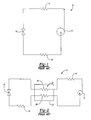
- FIG. 2 illustrates a vapor compression system 10 employing a suction line heat exchanger (SLHX) 20.
- the suction line heat exchanger 20 increases the efficiency and/or capacity of the vapor compression system 10, and prevents ingestion of liquid refrigerant into the compressor 12, which can be detrimental to the system 10.
- This invention regulates the high pressure component of the vapor compression system 10 to achieve the optimal pressure by adding excess charge to or removing excess charge from the system 10 and storing it in the suction line heat exchanger 20 storage tank 22.
- the enthalpy of the refrigerant at the entry of the evaporator can be modified, controlling the capacity of the system 10.
- the refrigerant exits the compressor 12 at high pressure and enthalpy, shown by point A in Figure 3.
- the refrigerant flows through the gas cooler 14 at high pressure, it loses heat and enthalpy, exiting the gas cooler 14 with low enthalpy and high pressure, indicated as point B.
- the hot refrigerant fluid passes through the suction line heat exchanger 20 before entering the expansion device 16.
- the refrigerant travels through the storage tank 20 along a first conduit 24 which connects the exit of the gas cooler 14 to the entry of the expansion device 16.
- the pressure drops, shown by point C.
- the refrigerant After expansion, the refrigerant passes through the evaporator 18 and exits at a high enthalpy and low pressure, represented by point D.
- the cool vapor refrigerant then reenters the storage tank 22 and travels along a second conduit 26 which connects the exit of the evaporator 18 to the entry of the compressor 12. After the refrigerant passes through the compressor 12, it is again at high pressure and enthalpy, completing the cycle.
- the suction line heat exchanger 20 exchanges heat internally between the high pressure hot refrigerant fluid discharged from the gas cooler 14 and the low pressure cool refrigerant vapor discharged from the evaporator 18.
- the pressure in the storage tank 22 is intermediate to the high and low pressures of the system.
- the pressure in the gas cooler 14 is regulated by adjusting valves 28 and 30 in the suction line heat exchanger 20.
- the first valve 28 is located in the storage tank 22 along the first conduit 24, and the second valve 30 is located in the storage tank 22 along the second conduit 26.
- a control 50 senses pressure in the cooler 14 and controls valves 28 and 30.
- the control 50 may be the main control for cycle 10.
- Control 50 is programmed to evaluate the state the cycle 10 and determine a desired pressure in cooler 14. Once a desired pressure has been determined, the valves 28 and 30 are controlled to regulate the pressure. The factors that would be used to determine the optimum pressure are within the skill of a worker in the art.
- control 50 determines the pressure is higher than desired, the first valve 28 is opened to allow charge from the gas cooler 14 to enter the storage tank 22, decreasing the pressure in the gas cooler 14 from A to A" (shown in Figure 3), requiring less energy to run the system.
- the refrigerant then enters the evaporator 18 at a higher enthalpy, represented by point C" in Figure 3.
- the system is not running at maximum capacity. If control 50 determines the pressure is lower then desirable, the second valve 30 is opened and charge from the storage tank 22 flows back into the system 10 to increase capacity.
- the gas cooler 14 pressure increases from A to A' and the refrigerant reenters the evaporator 18 at a lower enthalpy, shown by point C' in Figure 3.
- the enthalpy can be modified to achieve optimal capacity.
- Control 50 is preferably a microprocessor based control or other known controls such as known in the art of refrigerant cycles. While the actuation of the first valve 28 and the second valve 30 can be controlled actively by a control, it could also be controlled passively, such as by pressure relief valves 28 and 30. By controlling the actuation the valves 28 and 30, the high pressure in the gas cooler 14 can be optimally set and controlled, increasing the cooling capacity of the system 10.
- the storage tank 22 is long and of a small diameter. Since the wall thickness of the storage tank 22 is a function of diameter, the tank should be of a small diameter 36 to reduce weight.
- the present invention provides a suction line heat exchanger 20 which provides a means for controlling the high pressure in a transcritical vapor compression system 10.
Landscapes
- Engineering & Computer Science (AREA)
- Physics & Mathematics (AREA)
- Mechanical Engineering (AREA)
- Thermal Sciences (AREA)
- General Engineering & Computer Science (AREA)
- Chemical & Material Sciences (AREA)
- Chemical Kinetics & Catalysis (AREA)
- Filling Or Discharging Of Gas Storage Vessels (AREA)
- Sorption Type Refrigeration Machines (AREA)
- Compression-Type Refrigeration Machines With Reversible Cycles (AREA)
- Heat-Pump Type And Storage Water Heaters (AREA)
Abstract
Description
Claims (10)
- A suction line heat exchanger (20) for regulating a high pressure of a refrigerant circulating in a transcritical vapor compression system comprising:a storage tank (22) for storing charge;a first conduit (24) passing though said storage tank connecting a heat rejecting heat exchanger (14) to an expansion device (16), said refrigerant traveling through said first conduit (24) at a high pressure.a second conduit (26) passing through said storage tank (22) connecting a heat accepting heat exchanger (18) to a compression device (12), said refrigerant traveling though said second conduit (26) at a low pressure.a first valve (28) located on said first conduit (24) to regulate flow of said charge into said storage tank (22), said first valve (28) actuated by a controller (50) monitoring said high pressure; anda second valve (30) located on said second conduit (26) to regulate flow of said charge out of said storage tank (22), said second valve (30) actuated by a controller (50) monitoring said high pressure.
- The suction line heat exchanger as recited in claim 1 wherein decreasing said high pressure is achieved by actuating said first valve (28) to regulate flow of said charge from said system into said storage tank (22).
- The suction line heat exchanger as recited in claim 1 or 2 wherein increasing said high pressure is achieved by actuating said second valve (30) to regulate flow of said charge from storage tank (22) into said system.
- The suction line heat exchanger as recited in any preceding claim wherein said first valve (28) and said second valve (30) are controlled by an active control (50) which is provided with feedback from said heat rejecting heat exchanger (14), and determines a desired pressure at said heat rejecting heat exchanger (14), and controls said valves to achieve said desired pressure.
- A transcritical vapor compression system comprising:a compression device (12) to compress a refrigerant to a high pressure;a heat rejecting heat exchanger (14) for cooling said refrigerant;an expansion device (16) for reducing said refrigerant to a low pressure;a heat accepting heat exchanger (18) for evaporating said refrigerant; anda suction line heat exchanger (20) for regulating said high pressure of said refrigerant comprising a storage tank (22) for storing charge, a first conduit (24) connecting said heat rejecting heat exchanger (14) to said expansion device, a second conduit (26) connecting said heat accepting heat exchanger (18) to said compression device (12), a first valve (28) located on said first conduit to regulate flow of said charge into said storage tank (22), and a second valve (30) located on said second conduit (26) to regulate flow of said charge out of said storage tank (22).
- The system as recited in claim 5 wherein decreasing said high pressure is achieved by actuating said first valve (28) to regulate flow of said charge from said system into said storage tank (22).
- The system as recited in claim 6 wherein increasing said high pressure is achieved by actuating said second valve (30) to regulate flow of said charge from storage tank (22) into said system.
- The system as recited in claim 5, 6 or 7 wherein said first valve (28) and said second valve (30) are controlled by an active control (50) which is provided with feedback from said heat rejecting heat exchanger (14), and determines a desired pressure at said heat rejecting heat exchanger (14), and controls said valves (28,30) to achieve said desired pressure.
- The system or heat exchanger as recited in any preceding claim wherein said refrigerant is carbon dioxide.
- A method of regulation of a high pressure of a transcritical vapor compression system comprising the steps of:compressing a refrigerant to said high pressure;cooling said refrigerant;passing said refrigerant through a first conduit in a suction line heat exchanger storage tank, said first conduit having a first valve to regulate flow of said charge into said storage tank;expanding said refrigerant;evaporating said refrigerant;passing said refrigerant through a second conduit in a suction line heat exchanger storage tank, said second conduit having a second valve to regulate flow of said charge out of said storage tank; andcontrolling said high pressure of said refrigerant by actuating said first valve and said second valve.
Applications Claiming Priority (2)
| Application Number | Priority Date | Filing Date | Title |
|---|---|---|---|
| US09/713,122 US6606867B1 (en) | 2000-11-15 | 2000-11-15 | Suction line heat exchanger storage tank for transcritical cycles |
| US713122 | 2000-11-15 |
Publications (3)
| Publication Number | Publication Date |
|---|---|
| EP1207360A2 true EP1207360A2 (en) | 2002-05-22 |
| EP1207360A3 EP1207360A3 (en) | 2002-08-28 |
| EP1207360B1 EP1207360B1 (en) | 2007-02-21 |
Family
ID=24864825
Family Applications (1)
| Application Number | Title | Priority Date | Filing Date |
|---|---|---|---|
| EP01309595A Expired - Lifetime EP1207360B1 (en) | 2000-11-15 | 2001-11-14 | Suction line heat exchanger with a storage tank for a transcritical vapor compression cycle |
Country Status (9)
| Country | Link |
|---|---|
| US (1) | US6606867B1 (en) |
| EP (1) | EP1207360B1 (en) |
| JP (1) | JP3983520B2 (en) |
| CN (1) | CN1204368C (en) |
| AU (1) | AU767852B2 (en) |
| DE (1) | DE60126724T2 (en) |
| DK (1) | DK1207360T3 (en) |
| ES (1) | ES2278698T3 (en) |
| TW (1) | TW589442B (en) |
Cited By (3)
| Publication number | Priority date | Publication date | Assignee | Title |
|---|---|---|---|---|
| EP1367344A3 (en) * | 2002-05-30 | 2004-01-02 | Praxair Technology, Inc. | Method for operating a transcritical refrigeration system |
| NL1026728C2 (en) * | 2004-07-26 | 2006-01-31 | Antonie Bonte | Improvement of cooling systems. |
| EP1818627A4 (en) * | 2004-11-29 | 2009-04-29 | Mitsubishi Electric Corp | REFRIGERANT AIR CONDITIONER, METHOD FOR MANAGING ITS OPERATION, AND METHOD FOR MANAGING ITS QUANTITY OF REFRIGERANT AGENT |
Families Citing this family (18)
| Publication number | Priority date | Publication date | Assignee | Title |
|---|---|---|---|---|
| NO317847B1 (en) * | 2002-12-23 | 2004-12-20 | Sinvent As | Method for regulating a vapor compression system |
| NO318864B1 (en) * | 2002-12-23 | 2005-05-18 | Sinvent As | Improved heat pump system |
| US7096679B2 (en) * | 2003-12-23 | 2006-08-29 | Tecumseh Products Company | Transcritical vapor compression system and method of operating including refrigerant storage tank and non-variable expansion device |
| CN1333228C (en) * | 2005-01-26 | 2007-08-22 | 清华大学 | Microchannel slab internal heat exchanger of overcritical Co2 refrigerating circulation |
| CN101124438B (en) * | 2005-02-18 | 2010-08-04 | 卡里尔公司 | CO2 refrigeration plant with heat recovery |
| US20070095087A1 (en) * | 2005-11-01 | 2007-05-03 | Wilson Michael J | Vapor compression cooling system for cooling electronics |
| CN101548142B (en) * | 2006-11-30 | 2013-04-24 | 开利公司 | Refrigerant charge storage |
| DE102007035110A1 (en) * | 2007-07-20 | 2009-01-22 | Visteon Global Technologies Inc., Van Buren | Automotive air conditioning and method of operation |
| DK2229579T3 (en) * | 2008-01-17 | 2018-12-17 | Carrier Corp | Detection of CO2 emissions in a container |
| EP2229562B1 (en) * | 2008-01-17 | 2018-09-05 | Carrier Corporation | Carbon dioxide refrigerant vapor compression system |
| US9989280B2 (en) * | 2008-05-02 | 2018-06-05 | Heatcraft Refrigeration Products Llc | Cascade cooling system with intercycle cooling or additional vapor condensation cycle |
| FR2984472B1 (en) * | 2011-12-20 | 2015-10-02 | Astrium Sas | PASSIVE THERMAL CONTROL DEVICE |
| US9234685B2 (en) * | 2012-08-01 | 2016-01-12 | Thermo King Corporation | Methods and systems to increase evaporator capacity |
| US20160223239A1 (en) * | 2015-01-31 | 2016-08-04 | Trane International Inc. | Indoor Liquid/Suction Heat Exchanger |
| US10543737B2 (en) | 2015-12-28 | 2020-01-28 | Thermo King Corporation | Cascade heat transfer system |
| CN108775266B (en) * | 2018-06-11 | 2020-12-15 | 山东理工大学 | A combined heat and power system combining transcritical carbon dioxide power cycle and absorption heat pump for waste heat recovery of high temperature flue gas |
| CN110031362B (en) * | 2019-02-26 | 2024-10-22 | 中国科学技术大学 | A steam extensional rheometer |
| CN115435581A (en) * | 2021-06-02 | 2022-12-06 | 中山市爱美泰电器有限公司 | Double-refrigerant coupling high-temperature drying system containing carbon dioxide |
Family Cites Families (13)
| Publication number | Priority date | Publication date | Assignee | Title |
|---|---|---|---|---|
| CH425848A (en) * | 1964-12-15 | 1966-12-15 | Sulzer Ag | Gas refrigeration system |
| US4030315A (en) * | 1975-09-02 | 1977-06-21 | Borg-Warner Corporation | Reverse cycle heat pump |
| US4316366A (en) * | 1980-04-21 | 1982-02-23 | Carrier Corporation | Method and apparatus for integrating components of a refrigeration system |
| US5245836A (en) | 1989-01-09 | 1993-09-21 | Sinvent As | Method and device for high side pressure regulation in transcritical vapor compression cycle |
| US5095712A (en) * | 1991-05-03 | 1992-03-17 | Carrier Corporation | Economizer control with variable capacity |
| JPH085185A (en) * | 1994-06-16 | 1996-01-12 | Mitsubishi Electric Corp | Refrigeration cycle system |
| JPH0949662A (en) * | 1995-08-09 | 1997-02-18 | Aisin Seiki Co Ltd | Compression air conditioner |
| JPH1019421A (en) | 1996-07-05 | 1998-01-23 | Nippon Soken Inc | Refrigeration cycle and accumulator used for this cycle |
| JPH1163686A (en) | 1997-08-12 | 1999-03-05 | Zexel Corp | Refrigeration cycle |
| JPH11193967A (en) * | 1997-12-26 | 1999-07-21 | Zexel:Kk | Refrigerating cycle |
| JP2000179960A (en) * | 1998-12-18 | 2000-06-30 | Sanden Corp | Vapor compression type refrigeration cycle |
| US6182467B1 (en) * | 1999-09-27 | 2001-02-06 | Carrier Corporation | Lubrication system for screw compressors using an oil still |
| US6202438B1 (en) * | 1999-11-23 | 2001-03-20 | Scroll Technologies | Compressor economizer circuit with check valve |
-
2000
- 2000-11-15 US US09/713,122 patent/US6606867B1/en not_active Expired - Lifetime
-
2001
- 2001-10-25 TW TW090126389A patent/TW589442B/en not_active IP Right Cessation
- 2001-11-12 JP JP2001346143A patent/JP3983520B2/en not_active Expired - Fee Related
- 2001-11-13 AU AU89403/01A patent/AU767852B2/en not_active Ceased
- 2001-11-14 EP EP01309595A patent/EP1207360B1/en not_active Expired - Lifetime
- 2001-11-14 DK DK01309595T patent/DK1207360T3/en active
- 2001-11-14 ES ES01309595T patent/ES2278698T3/en not_active Expired - Lifetime
- 2001-11-14 DE DE60126724T patent/DE60126724T2/en not_active Expired - Lifetime
- 2001-11-15 CN CN01137473.XA patent/CN1204368C/en not_active Expired - Fee Related
Cited By (4)
| Publication number | Priority date | Publication date | Assignee | Title |
|---|---|---|---|---|
| EP1367344A3 (en) * | 2002-05-30 | 2004-01-02 | Praxair Technology, Inc. | Method for operating a transcritical refrigeration system |
| NL1026728C2 (en) * | 2004-07-26 | 2006-01-31 | Antonie Bonte | Improvement of cooling systems. |
| EP1818627A4 (en) * | 2004-11-29 | 2009-04-29 | Mitsubishi Electric Corp | REFRIGERANT AIR CONDITIONER, METHOD FOR MANAGING ITS OPERATION, AND METHOD FOR MANAGING ITS QUANTITY OF REFRIGERANT AGENT |
| US8109105B2 (en) | 2004-11-29 | 2012-02-07 | Mitsubishi Electric Corporation | Refrigerating air conditioning system, method of controlling operation of refrigerating air conditioning system, and method of controlling amount of refrigerant in refrigerating air conditioning system |
Also Published As
| Publication number | Publication date |
|---|---|
| DE60126724T2 (en) | 2007-11-15 |
| TW589442B (en) | 2004-06-01 |
| AU8940301A (en) | 2002-05-16 |
| CN1204368C (en) | 2005-06-01 |
| JP3983520B2 (en) | 2007-09-26 |
| DE60126724D1 (en) | 2007-04-05 |
| AU767852B2 (en) | 2003-11-27 |
| DK1207360T3 (en) | 2007-06-18 |
| CN1353283A (en) | 2002-06-12 |
| ES2278698T3 (en) | 2007-08-16 |
| EP1207360B1 (en) | 2007-02-21 |
| US6606867B1 (en) | 2003-08-19 |
| JP2002195670A (en) | 2002-07-10 |
| EP1207360A3 (en) | 2002-08-28 |
Similar Documents
| Publication | Publication Date | Title |
|---|---|---|
| EP1207360B1 (en) | Suction line heat exchanger with a storage tank for a transcritical vapor compression cycle | |
| US6418735B1 (en) | High pressure regulation in transcritical vapor compression cycles | |
| EP1631773B1 (en) | Supercritical pressure regulation of economized refrigeration system | |
| EP1207359B1 (en) | High pressure regulation in a transcritical vapor compression cycle | |
| US7484374B2 (en) | Flash tank design and control for heat pumps | |
| US6698234B2 (en) | Method for increasing efficiency of a vapor compression system by evaporator heating | |
| US6898941B2 (en) | Supercritical pressure regulation of vapor compression system by regulation of expansion machine flowrate | |
| JPH11193967A (en) | Refrigerating cycle | |
| US6739141B1 (en) | Supercritical pressure regulation of vapor compression system by use of gas cooler fluid pumping device | |
| JP2000346472A (en) | Supercritical steam compression cycle | |
| JP2002310519A (en) | Heat pump water heater | |
| JP2002228282A (en) | Refrigeration equipment | |
| JP4334818B2 (en) | Cooling system | |
| JP2002310497A (en) | Heat pump water heater | |
| JPH10259959A (en) | Heating device using refrigeration cycle | |
| JP2002310498A (en) | Heat pump water heater | |
| KR102966981B1 (en) | Hybrid multi-air conditioning system | |
| JPH067028B2 (en) | Heat pump type air conditioner |
Legal Events
| Date | Code | Title | Description |
|---|---|---|---|
| PUAI | Public reference made under article 153(3) epc to a published international application that has entered the european phase |
Free format text: ORIGINAL CODE: 0009012 |
|
| AX | Request for extension of the european patent |
Free format text: AL;LT;LV;MK;RO;SI |
|
| PUAL | Search report despatched |
Free format text: ORIGINAL CODE: 0009013 |
|
| AK | Designated contracting states |
Kind code of ref document: A3 Designated state(s): AT BE CH CY DE DK ES FI FR GB GR IE IT LI LU MC NL PT SE TR |
|
| AX | Request for extension of the european patent |
Free format text: AL;LT;LV;MK;RO;SI |
|
| RIC1 | Information provided on ipc code assigned before grant |
Free format text: 7F 25B 9/00 A, 7F 25B 40/00 B, 7F 25B 45/00 B |
|
| 17P | Request for examination filed |
Effective date: 20020819 |
|
| AKX | Designation fees paid |
Designated state(s): DE DK ES IE IT NL |
|
| 17Q | First examination report despatched |
Effective date: 20050308 |
|
| GRAP | Despatch of communication of intention to grant a patent |
Free format text: ORIGINAL CODE: EPIDOSNIGR1 |
|
| RAP1 | Party data changed (applicant data changed or rights of an application transferred) |
Owner name: CARRIER CORPORATION |
|
| GRAS | Grant fee paid |
Free format text: ORIGINAL CODE: EPIDOSNIGR3 |
|
| GRAA | (expected) grant |
Free format text: ORIGINAL CODE: 0009210 |
|
| AK | Designated contracting states |
Kind code of ref document: B1 Designated state(s): DE DK ES IE IT NL |
|
| REF | Corresponds to: |
Ref document number: 60126724 Country of ref document: DE Date of ref document: 20070405 Kind code of ref document: P |
|
| REG | Reference to a national code |
Ref country code: IE Ref legal event code: FG4D |
|
| REG | Reference to a national code |
Ref country code: DK Ref legal event code: T3 |
|
| REG | Reference to a national code |
Ref country code: ES Ref legal event code: FG2A Ref document number: 2278698 Country of ref document: ES Kind code of ref document: T3 |
|
| PLBE | No opposition filed within time limit |
Free format text: ORIGINAL CODE: 0009261 |
|
| STAA | Information on the status of an ep patent application or granted ep patent |
Free format text: STATUS: NO OPPOSITION FILED WITHIN TIME LIMIT |
|
| 26N | No opposition filed |
Effective date: 20071122 |
|
| PGFP | Annual fee paid to national office [announced via postgrant information from national office to epo] |
Ref country code: DK Payment date: 20071010 Year of fee payment: 7 Ref country code: ES Payment date: 20071105 Year of fee payment: 7 Ref country code: NL Payment date: 20071010 Year of fee payment: 7 |
|
| REG | Reference to a national code |
Ref country code: DK Ref legal event code: EBP |
|
| PG25 | Lapsed in a contracting state [announced via postgrant information from national office to epo] |
Ref country code: NL Free format text: LAPSE BECAUSE OF NON-PAYMENT OF DUE FEES Effective date: 20090601 |
|
| NLV4 | Nl: lapsed or anulled due to non-payment of the annual fee |
Effective date: 20090601 |
|
| PGFP | Annual fee paid to national office [announced via postgrant information from national office to epo] |
Ref country code: IE Payment date: 20071030 Year of fee payment: 7 |
|
| PG25 | Lapsed in a contracting state [announced via postgrant information from national office to epo] |
Ref country code: IE Free format text: LAPSE BECAUSE OF NON-PAYMENT OF DUE FEES Effective date: 20081114 Ref country code: DK Free format text: LAPSE BECAUSE OF NON-PAYMENT OF DUE FEES Effective date: 20081130 |
|
| REG | Reference to a national code |
Ref country code: ES Ref legal event code: FD2A Effective date: 20081115 |
|
| PG25 | Lapsed in a contracting state [announced via postgrant information from national office to epo] |
Ref country code: ES Free format text: LAPSE BECAUSE OF NON-PAYMENT OF DUE FEES Effective date: 20081115 |
|
| PGFP | Annual fee paid to national office [announced via postgrant information from national office to epo] |
Ref country code: IT Payment date: 20121114 Year of fee payment: 12 |
|
| PG25 | Lapsed in a contracting state [announced via postgrant information from national office to epo] |
Ref country code: IT Free format text: LAPSE BECAUSE OF NON-PAYMENT OF DUE FEES Effective date: 20131114 |
|
| PGFP | Annual fee paid to national office [announced via postgrant information from national office to epo] |
Ref country code: DE Payment date: 20161020 Year of fee payment: 16 |
|
| REG | Reference to a national code |
Ref country code: DE Ref legal event code: R082 Ref document number: 60126724 Country of ref document: DE Representative=s name: SCHMITT-NILSON SCHRAUD WAIBEL WOHLFROM PATENTA, DE |
|
| REG | Reference to a national code |
Ref country code: DE Ref legal event code: R119 Ref document number: 60126724 Country of ref document: DE |
|
| PG25 | Lapsed in a contracting state [announced via postgrant information from national office to epo] |
Ref country code: DE Free format text: LAPSE BECAUSE OF NON-PAYMENT OF DUE FEES Effective date: 20180602 |