EP1207332A2 - Flow control valve coupling structure - Google Patents
Flow control valve coupling structure Download PDFInfo
- Publication number
- EP1207332A2 EP1207332A2 EP01126563A EP01126563A EP1207332A2 EP 1207332 A2 EP1207332 A2 EP 1207332A2 EP 01126563 A EP01126563 A EP 01126563A EP 01126563 A EP01126563 A EP 01126563A EP 1207332 A2 EP1207332 A2 EP 1207332A2
- Authority
- EP
- European Patent Office
- Prior art keywords
- flow control
- control valve
- grommet
- sealing member
- elastic sealing
- Prior art date
- Legal status (The legal status is an assumption and is not a legal conclusion. Google has not performed a legal analysis and makes no representation as to the accuracy of the status listed.)
- Granted
Links
- 230000008878 coupling Effects 0.000 title claims abstract description 128
- 238000010168 coupling process Methods 0.000 title claims abstract description 128
- 238000005859 coupling reaction Methods 0.000 title claims abstract description 128
- 238000007789 sealing Methods 0.000 claims abstract description 22
- 230000002093 peripheral effect Effects 0.000 claims abstract description 13
- 229920003002 synthetic resin Polymers 0.000 claims description 7
- 239000000057 synthetic resin Substances 0.000 claims description 7
- 238000002485 combustion reaction Methods 0.000 claims description 5
- 229920001971 elastomer Polymers 0.000 claims description 2
- 239000000463 material Substances 0.000 claims description 2
- 230000013011 mating Effects 0.000 claims description 2
- 239000005060 rubber Substances 0.000 claims description 2
- 238000003754 machining Methods 0.000 abstract description 5
- 238000009434 installation Methods 0.000 abstract 1
- 238000004891 communication Methods 0.000 description 6
- 230000007423 decrease Effects 0.000 description 4
- 229920003051 synthetic elastomer Polymers 0.000 description 3
- 239000005061 synthetic rubber Substances 0.000 description 3
- 230000015572 biosynthetic process Effects 0.000 description 1
- 239000000919 ceramic Substances 0.000 description 1
- 230000003247 decreasing effect Effects 0.000 description 1
- 239000002184 metal Substances 0.000 description 1
- 238000000034 method Methods 0.000 description 1
Images




Classifications
-
- F—MECHANICAL ENGINEERING; LIGHTING; HEATING; WEAPONS; BLASTING
- F01—MACHINES OR ENGINES IN GENERAL; ENGINE PLANTS IN GENERAL; STEAM ENGINES
- F01M—LUBRICATING OF MACHINES OR ENGINES IN GENERAL; LUBRICATING INTERNAL COMBUSTION ENGINES; CRANKCASE VENTILATING
- F01M13/00—Crankcase ventilating or breathing
-
- F—MECHANICAL ENGINEERING; LIGHTING; HEATING; WEAPONS; BLASTING
- F16—ENGINEERING ELEMENTS AND UNITS; GENERAL MEASURES FOR PRODUCING AND MAINTAINING EFFECTIVE FUNCTIONING OF MACHINES OR INSTALLATIONS; THERMAL INSULATION IN GENERAL
- F16L—PIPES; JOINTS OR FITTINGS FOR PIPES; SUPPORTS FOR PIPES, CABLES OR PROTECTIVE TUBING; MEANS FOR THERMAL INSULATION IN GENERAL
- F16L41/00—Branching pipes; Joining pipes to walls
- F16L41/08—Joining pipes to walls or pipes, the joined pipe axis being perpendicular to the plane of a wall or to the axis of another pipe
- F16L41/088—Joining pipes to walls or pipes, the joined pipe axis being perpendicular to the plane of a wall or to the axis of another pipe fixed using an elastic grommet between the extremity of the tube and the wall
-
- F—MECHANICAL ENGINEERING; LIGHTING; HEATING; WEAPONS; BLASTING
- F01—MACHINES OR ENGINES IN GENERAL; ENGINE PLANTS IN GENERAL; STEAM ENGINES
- F01M—LUBRICATING OF MACHINES OR ENGINES IN GENERAL; LUBRICATING INTERNAL COMBUSTION ENGINES; CRANKCASE VENTILATING
- F01M13/00—Crankcase ventilating or breathing
- F01M13/0011—Breather valves
-
- Y—GENERAL TAGGING OF NEW TECHNOLOGICAL DEVELOPMENTS; GENERAL TAGGING OF CROSS-SECTIONAL TECHNOLOGIES SPANNING OVER SEVERAL SECTIONS OF THE IPC; TECHNICAL SUBJECTS COVERED BY FORMER USPC CROSS-REFERENCE ART COLLECTIONS [XRACs] AND DIGESTS
- Y10—TECHNICAL SUBJECTS COVERED BY FORMER USPC
- Y10T—TECHNICAL SUBJECTS COVERED BY FORMER US CLASSIFICATION
- Y10T137/00—Fluid handling
- Y10T137/7504—Removable valve head and seat unit
- Y10T137/7613—Threaded into valve casing
-
- Y—GENERAL TAGGING OF NEW TECHNOLOGICAL DEVELOPMENTS; GENERAL TAGGING OF CROSS-SECTIONAL TECHNOLOGIES SPANNING OVER SEVERAL SECTIONS OF THE IPC; TECHNICAL SUBJECTS COVERED BY FORMER USPC CROSS-REFERENCE ART COLLECTIONS [XRACs] AND DIGESTS
- Y10—TECHNICAL SUBJECTS COVERED BY FORMER USPC
- Y10T—TECHNICAL SUBJECTS COVERED BY FORMER US CLASSIFICATION
- Y10T137/00—Fluid handling
- Y10T137/7722—Line condition change responsive valves
- Y10T137/7837—Direct response valves [i.e., check valve type]
- Y10T137/7854—In couplings for coaxial conduits, e.g., drill pipe check valves
-
- Y—GENERAL TAGGING OF NEW TECHNOLOGICAL DEVELOPMENTS; GENERAL TAGGING OF CROSS-SECTIONAL TECHNOLOGIES SPANNING OVER SEVERAL SECTIONS OF THE IPC; TECHNICAL SUBJECTS COVERED BY FORMER USPC CROSS-REFERENCE ART COLLECTIONS [XRACs] AND DIGESTS
- Y10—TECHNICAL SUBJECTS COVERED BY FORMER USPC
- Y10T—TECHNICAL SUBJECTS COVERED BY FORMER US CLASSIFICATION
- Y10T137/00—Fluid handling
- Y10T137/7722—Line condition change responsive valves
- Y10T137/7837—Direct response valves [i.e., check valve type]
- Y10T137/7854—In couplings for coaxial conduits, e.g., drill pipe check valves
- Y10T137/7855—Valve seat threaded into a coupling element
Definitions
- the present invention is related to a coupling structure of a flow control valve, and more particularly, to a coupling structure of a flow control valve for a blowby gas returning apparatus that is provided in an internal combustion engine.
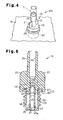
- Fig. 1 is a cross-sectional view showing a first example of a conventional flow control valve coupling structure 50 for a blowby gas returning apparatus (hereinafter a PCV valve).
- a fitting portion 62 of the PCV valve 61 is fitted axially to a coupling hole 60 that is provided in a cylinder head cover H.
- the PCV valve 61 is detachably coupled to the cylinder head cover H.
- a cylindrical grommet 63 is first fitted to the coupling hole 60.
- the fitting portion 62 of the PCV valve 61 is fitted to a mounting hole 63a of the grommet 63 thereby coupling the PCV valve 61 to the cylinder head cover H.
- the cylinder head cover H is required to undergo only machining to form the round coupling hole 60.
- the fitting allowance of the fitting portion 62 requires high accuracy so that the fitting portion 62 of the PCV valve 61 does not fall out of the grommet 63. This increases the number of steps necessary for fitting the PCV valve 61 in the grommet 63.
- Fig. 2 is a cross-sectional view showing a second example of a conventional PCV valve coupling structure 50A.
- the coupling structure 50A is disclosed in Japanese Unexamined Patent Publication No. 2000-161040.
- a female thread is formed in a coupling hole 70 of the cylinder head cover H and a male thread is formed on a fitting portion 71 of the PCV valve 72.
- the PCV valve 72 is coupled to the cylinder head cover H by screwing the fitting portion 71 into the coupling hole 70.
- the coupling structure 50A does not use a grommet, vibration of the internal combustion engine is transmitted directly to the PCV valve 72. Further, the machining of the female thread in the coupling hole 70 increases the number of steps required to couple the PCV valve 72 to the cylinder head cover H.
- the present invention provides a coupling structure for a flow control valve.
- the coupling structure includes a fitting portion having a male thread that is formed on a peripheral surface of the flow control valve.
- a coupled member has a coupling hole to receive the flow control valve.
- a cylindrical elastic sealing member is engaged with the coupling hole to seal the space between the flow control valve and the coupling hole.
- the elastic sealing member has an inner surface defining a mounting hole in which the fitting portion is fitted.
- a female thread is formed on the inner surface. The female thread is mated with the male thread of the fitting portion.
- a further aspect of the present invention is a flow control valve received in a predetermined coupling hole.
- the valve includes a fitting portion engaged with the coupling hole and having a peripheral surface.
- a male thread is formed on the peripheral surface.
- a main body is connected to the fitting portion and formed from synthetic resin.
- a further aspect of the present invention is a cylindrical elastic sealing member formed from a rubber material.
- the elastic sealing member receives a fitting body.
- the elastic sealing member includes a mounting hole for receiving the fitting body.
- a pressed portion is formed on a inner surface defining the mounting hole and pressed by the fitting body. The pressed portion radially expands the elastic sealing member when pressed by the fitting body.
- Fig. 3 is a schematic cross-sectional view showing a PCV valve coupling structure 100 according to a first embodiment of the present invention.
- the PCV valve coupling structure 100 includes a PCV valve 10 and a grommet (an elastic sealing member) 12.
- the PCV valve 10 is detachably engaged with a coupling hole 11 (shown in Fig. 3), which is formed in an engine cylinder head cover H, by means of the grommet 12.
- the head cover H serves as a coupled member to which the PCV valve 10 is coupled.
- a tubing hose T which is connected to an intake system of an intake manifold (not shown), is connected to the PCV valve 10.
- the PCV valve 10 includes a main body 13, a valve body 14, and a coil spring 15.
- the main body 13 includes a lower piece 16 and an upper piece 17, each of which is formed integrally from synthetic resin.
- the lower piece 16 includes a generally cylindrical fitting portion 18.
- a generally cylindrical valve chamber 22 is formed in the fitting portion 18.
- the valve chamber 22 is communicated with the atmosphere via a valve hole 22a, which extends through the bottom of the fitting portion 18.
- a male thread 23 is formed on the peripheral surface of the fitting portion 18.
- the upper piece 17 includes a generally cylindrical base 19, a hose connector 20, and tabs 21.
- the base 19 has a diameter larger than that of the fitting portion 18.
- the hose connector 20 is generally cylindrical and extends upward from the base 19.
- the tabs 21, which define a rotating portion, are thin plates extending from opposite sides of the hose connector 20. When the PCV valve 10 is attached to or detached from the head cover, the tabs 21 are used to rotate the PCV valve 10. When the tubing hose T is connected to the hose connector 20, the tabs 21 are used to position the tubing hose T.
- a lower communication hole 24 that communicates with the upper portion of the valve chamber 22 extends through the base 19.
- a step 25 facing the valve chamber 22 is formed in the lower communication hole 24.
- the tubing hose T is connected to the hose connector 20.
- the upper communication hole 26 is communicated with the intake system of the engine by the tubing hose T.
- the cylindrical valve body 14 is arranged in the valve chamber 22 and formed integrally from synthetic resin.
- the valve body 14 moves axially and has a predetermined stroke.
- the valve body 14 has a lower end, from which a valve flange 27 extends, and an upper end, on which a valve portion 28 is defined.
- the valve flange 27 slidably contacts the wall surface of the valve chamber 22 at three points to radially support the lower portion of the valve body 14.
- the valve flange 27 divides the valve chamber 22 into an upper portion and a lower portion, and the upper portion and the lower portion are communicated with each other through the valve flange 27.
- the valve flange 27 closes the valve hole 22a.
- the cross-sectional area of a flow passage defined between the step 25 and the valve portion 28 is maximum.
- the cross-sectional area of the flow passage becomes smaller as the valve body 14 moves upward.
- the coil spring 15 is fitted on the valve body 14 and arranged between the step 25 and the valve flange 27.
- the coil spring 15 urges the valve body 14 downward and causes the valve flange 27 to close the valve hole 22a when an upward force is not applied to the valve body 14.
- the negative pressure in the intake system of the engine is communicated to the valve chamber 22 via the lower and upper communication holes 24, 26 by the tubing hose T.
- the valve body 14 moves upward against the urging force of the coil spring 15 in accordance with the negative pressure and opens the valve hole 22a.
- the cross-sectional area of the flow passage decreases. This decreases the amount of blowby gas that flow through the valve hole 22a toward the intake system.
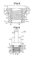
- the grommet 12 is cylindrical and formed integrally from synthetic rubber.
- a grommet flange 29 extends from the basal end (the left end as viewed in Fig. 6A) of the grommet 12.
- the outer diameter of the grommet 12 decreases from the basal end, in'which the flange is formed, to the distal end. That is, a tapered surface 30 is defined on part of the peripheral surface of the grommet 12.
- a groove 31 extends between the tapered surface 30 and the grommet flange 29.
- the maximum outer diameter of the tapered surface 30 is slightly greater than the inner diameter of the coupling hole 11. When the grommet 12 is fitted in the coupling hole 11, it deforms slightly and the diameter of the tapered surface 30 is slightly decreased.
- the groove 31 has an outer diameter that does not change when the grommet 12 is fitted in the coupling hole 11.
- the grommet 12 has a fitting hole (a female screw hole) 32, in which the fitting portion 18 of the PCV valve 10 is fitted.
- a female thread 32A which is meshed with a male thread 23 of the fitting portion 18, is formed on the surface of the female screw hole 32.
- a pressed portion 33 projects inward into an opening formed at the distal end of the grommet 12. The inner diameter of the pressed portion 33 is smaller than the root diameter of the male thread 23.
- a stopper 34 projects from the peripheral surface of the grommet 12 between the grommet flange 29 and the groove 31. The stopper 34 prevents the grommet 12 from rotating in the coupling hole 11 when the male thread 23 is meshed with the female thread 32A.
- the diameter of the coupling hole 11 is such that the groove 31 of the grommet 12 can be fitted in the coupling hole 11.
- a stopper socket (rotation restricting structure) 11a is provided in the surface of the cylinder head H adjacent to the coupling hole 11.
- the stopper (rotation restricting structure) 34 is received in the coupling hole 11 to restrict the rotation of the grommet 12 in the coupling hole 11.
- the PCV valve 10 is attached to the head cover H by fitting the grommet 12, to which the fitting portion 18 is attached, into the coupling hole 11.
- the distal end of the fitting portion 18 forces the pressed portion 33 outward (the direction indicated by arrow A). This radially expands the lower portion of the grommet 12.
- the distal end of the fitting portion 18 presses the pressed portion 33 and expands the grommet 12.
- the grommet 12 is coupled to the coupling hole 11 in a state in which its lower portion is radially expanded.
- the grommet 12 is fixed at a proper position by fitting the groove 31 in the coupling hole 11.
- the grommet 12 is pulled together with the PCV valve 10 from the coupling hole 11, the expanded lower portion of the grommet 12 prevents the grommet 12 from being removed from the coupling hole 11. Therefore, the grommet 12 is not pulled out of the coupling hole 11 with the PCV valve 10.
- the male thread 23 of the PCV valve 10 is halfway mated with the female thread 32A of the grommet 12 to engage the grommet 12 with the fitting portion 18.
- the fitting portion 18 is screwed into the female thread 32A until the distal end of the fitting portion 18 reaches a position just before the distal end applies force to the pressed portion 33 of the grommet 12 so that the lower portion (the lower portion as viewed in Fig. 7A) of the grommet 12 is not radially expanded.
- the tabs 21 are rotated to further screw the male thread 23 into the female thread 32A, as shown in the state of Fig. 3.
- the pressed portion 33 is forced outward by the distal end of the fitting portion 18. This radially expands the lower portion of the grommet 12.
- the expanded grommet 12 is fixed to the coupling hole 11, and the PCV valve 10 is coupled in the coupling hole 11 by means of the grommet 12.
- the male thread 23 of the fitting portion 18 is mated with the female thread 32A of the grommet 12.
- the distal end of the fitting portion 18 applies force to the pressed portion 33 and expands the pressed portion 33 outward.
- the PCV valve 10 is removed from the coupling hole 11 with the male thread 23 still halfway mated with the female thread 32A.
- the PCV valve 10 is removed from the coupling hole 11 with the grommet 12, as shown in the state of Fig. 7A.
- the male thread 23 may be completely disengaged from the female screw hole 32.
- the PCV valve 10 is removed from the coupling hole 11 with the grommet 12 engaged with the coupling hole 11.
- Fig. 9 is a schematic cross-sectional view showing a PCV coupling structure 200 according to a second embodiment of the present invention.
- the PCV valve coupling structure 200 includes a PCV valve 10 and a grommet 40.
- the PCV coupling structure 200 of the second embodiment differs from the coupling structure 100 of the first embodiment only in the grommet.
- the grommet 40 of the second embodiment is cylindrical and formed integrally from synthetic rubber or synthetic resin.
- a grommet flange 41 extends from the basal end (the left end in Fig. 10A) of the grommet 40.
- the diameter of the peripheral surface 40a of the grommet 40 is substantially equal to the diameter of the coupling hole 11. Therefore, when the grommet 40 is fitted in the coupling hole 11, the diameter of the peripheral surface 40a remains substantially the same.
- the grommet 40 has a mounting hole (a female screw hole) 42 in which the fitting portion 18 of the PCV valve 10 is received.
- a female thread 42A which is meshed with the male thread 23 of the fitting portion 18, is formed on the inner surface of the female screw hole (mounting hole) 42.
- Four equally spaced pressed portions 43 project radially from the inner surface at the distal end of the grommet 40.
- the diameter of a circle tangential to the distal ends of the four pressed portions 43 is smaller than the root diameter of the male thread 23.
- a stopper 44 is arranged on the peripheral surface 40a of the grommet 40 adjacent the grommet flange 41. When the male thread 23 is mated with the female thread 32A, the stopper 44 prevents the grommet 40 from rotating in the coupling hole 11.
- the PCV valve 10 is coupled to the head cover H by fitting the grommet 40, which is attached with the fitting portion 18, into the coupling hole 11.
- the distal end of the fitting portion 18 forces each of the pressed portions 43 outward (the direction indicated by arrow B) and expands the lower portion of the grommet 40 in the radial direction of the coupling hole 11.
- the enlarged grommet 40 is held in the coupling hole 11.
- the mating of the male thread 23 with the female thread 32A enlarges the distal end of the grommet 40 and fixes the PCV valve 10 in the axial direction.
- the female thread 42A is halfway mated with the male thread 23 of the PCV valve 10.
- the fitting portion 18 is screwed into the female screw hole 32 until the distal end of the fitting portion 18 reaches a position just before the distal end applies force to the pressed portions 43 of the grommet 40 so that the grommet 12 is not radially expanded.
- the grommet 40 which is attached with the fitting portion 18, is fitted in the coupling hole 11 so that an end surface of the grommet flange 41 contacts the surface of the head cover H.
- the stopper 44 is received in to the stopper socket 11a.
- the PCV valve 10 is rotated to fully mate the male thread 23 and the female thread 42A, as shown in the state of Fig. 9.
- the distal end of the fitting portion 18 applies outward force to each pressed portion 43 and radially expands the lower portion of the grommet 40.
- the expanded grommet 40 is fixed in the coupling hole 11. This, in turn, fixes the PCV valve 10, which is attached to the grommet 40, to the coupling hole 11.
- the grommet 40 may first be engaged with the coupling hole 11, and the male thread 23 of the fitting portion 18 may be mated with the female thread 42A afterward.
- the operator rotates the PCV valve 10 until the fitting portion 18 does not apply force to the pressed portions 43. This returns the grommet 40 returns to the state shown in Fig. 2 in which the lower portion is not expanded.
- the PCV valve 10 the male thread 23 of which is halfway mated with the female thread 42A, is pulled out of the coupling hole 11 together with the grommet 40. Alternatively, the male thread 23 may be fully disengaged from the female screw hole 42. In this state, the PCV valve 10 is removed from the coupling hole 11 with the grommet 40 remaining in the coupling hole 11.
- the four pressed portions 43 are equally spaced in the opening of the grommet 40, and the distal end of the fitting portion 18 applies force to the pressed portion 43 to expand the grommet 40. Accordingly, the entire circumference in the opening of the grommet 40 does not have to be enlarged. This enables the grommet 40 to be made of synthetic rubber or synthetic resin that is harder and has a longer durability.
- the male thread 23 may be formed only on the basal end of the fitting portion 18 and the female threads 32A, 42A may be formed only in part of the grommet flanges 29, 41. This facilitates the attachment of the grommet 12 to the PCV valve 10. Further, this results in forcible removal of the tubing hose T when the PCV valve 10 is coupled and removed.
- the male thread 23 of the fitting portion 18 and the female thread 32A of the grommet 12 do not have to be formed.
- the fitting portion 18 is fitted halfway in the grommet 12, to engage the grommet 12 with the fitting portion 18.
- the grommet 12 is fully fitted in the coupling hole 11 to expand the grommet 12.
- the coupling hole 11 does not necessarily have to be circular and may be, for example, elliptic or square. If the coupling hole 11 is square, the four corners may be curved.
- the pressed portions 33, 43 need not be formed in the female screw holes 32, 42 of the grommets 12, 40 so that the fitting portion 18 does not expand the grommets 12, 40.
- the tabs 21 may be replaced by, for example, a hexagonal nut.
- the main body 13 and the valve body 14 of the PCV valve 10 may be formed from metal or ceramic.
- the PCV valve may be coupled with to a coupling hole formed in a crank case.
Landscapes
- Engineering & Computer Science (AREA)
- General Engineering & Computer Science (AREA)
- Mechanical Engineering (AREA)
- Valve Housings (AREA)
- Lubrication Details And Ventilation Of Internal Combustion Engines (AREA)
- Taps Or Cocks (AREA)
- Lift Valve (AREA)
Abstract
Description
Claims (11)
- A coupling structure for a flow control valve, including a fitting portion (18) having a male thread (23) that is formed on a peripheral surface of the flow control valve, a coupled member (H) having a coupling hole (31) to receive the flow control valve, and a cylindrical elastic sealing member (12) engaged with the coupling hole to seal the space between the flow control valve and the coupling hole, the coupling structure being characterized in that the elastic sealing member has an inner surface defining a mounting hole (32) in which the fitting portion is fitted, and a female thread (32A) is formed on the inner surface, the female thread being mated with the male thread of the fitting portion.
- The coupling structure according to claim 1, characterized in that the elastic sealing member has a pressed portion (33) formed on the inner surface defining the mounting hole, and the pressed portion is pressed by the fitting portion to radially expand the elastic sealing member when the fitting portion is fitted in the mounting hole.
- The coupling structure according to claim 1 or 2, characterized in that the elastic sealing member and the coupled member hole each include a rotation restricting structure (11a, 34) that holds the elastic sealing member and prevents the elastic sealing member from rotating in the coupling hole when the male thread is mated with the female thread.
- The coupling structure according to claim 3, characterized in that the coupled member includes a front surface and a rear surface, the elastic sealing member being engaged with the coupled member from the front surface, and wherein the rotation restricting structure has a stopper socket (11a), which is arranged adjacent to the coupling hole, and a stopper (34), which projects from the elastic sealing member, the stopper being received in the stopper socket.
- The coupling structure according to any one of claims 1 to 4, characterized in that the flow control valve has a main body (13) formed from synthetic resin, and the main body has a rotating portion (21) for rotating the male thread and mating the male thread with the female thread.
- The coupling structure according to claim 5, characterized in that the main body has a hose connector (20) for connecting a hose, and the rotating portion is arranged in the hose connector.
- The coupling structure according to any one of claims 1 to 6, characterized in that the flow control valve is a blowby gas returning apparatus flow control valve incorporated in an internal combustion engine.
- A flow control valve received in a predetermined coupling hole, the valve being characterized by:a fitting portion (18) engaged with the coupling hole and having a peripheral surface, wherein a male thread (23) is formed on the peripheral surface; anda main body (13) connected to the fitting portion and formed from synthetic resin.
- The flow control valve according to claim 8, characterized in that the main body has a rotating portion (21) for rotating the fitting portion when engaging the flow control valve with the coupling hole.
- The flow control valve according to claim 8 or claim 9, characterized in that the flow control valve is a blowby gas returning apparatus flow control valve incorporated in an internal combustion engine.
- A cylindrical elastic sealing member formed from a rubber material, wherein the elastic sealing member receives a fitting body, the elastic sealing member being characterized by:a mounting hole (32) for receiving the fitting body; anda pressed portion (33) formed on a inner surface defining the mounting hole and pressed by the fitting body, wherein the pressed portion radially expands the elastic sealing member when pressed by the fitting body.
Applications Claiming Priority (2)
| Application Number | Priority Date | Filing Date | Title |
|---|---|---|---|
| JP2000351178A JP3889924B2 (en) | 2000-11-17 | 2000-11-17 | Mounting structure of flow control valve for blow-by gas reduction device |
| JP2000351178 | 2000-11-17 |
Publications (3)
| Publication Number | Publication Date |
|---|---|
| EP1207332A2 true EP1207332A2 (en) | 2002-05-22 |
| EP1207332A3 EP1207332A3 (en) | 2003-04-23 |
| EP1207332B1 EP1207332B1 (en) | 2005-08-24 |
Family
ID=18824283
Family Applications (1)
| Application Number | Title | Priority Date | Filing Date |
|---|---|---|---|
| EP01126563A Expired - Lifetime EP1207332B1 (en) | 2000-11-17 | 2001-11-15 | Flow control valve coupling structure |
Country Status (8)
| Country | Link |
|---|---|
| US (1) | US6883538B2 (en) |
| EP (1) | EP1207332B1 (en) |
| JP (1) | JP3889924B2 (en) |
| KR (1) | KR100398949B1 (en) |
| CN (1) | CN1246621C (en) |
| CA (1) | CA2363140C (en) |
| DE (2) | DE1207332T1 (en) |
| HK (1) | HK1043178A1 (en) |
Cited By (5)
| Publication number | Priority date | Publication date | Assignee | Title |
|---|---|---|---|---|
| WO2006077231A1 (en) * | 2005-01-18 | 2006-07-27 | Voss Automotive Gmbh | Connecting device for media pipes |
| WO2007112992A1 (en) | 2006-04-05 | 2007-10-11 | Rehau Ag + Co | Connecting device for a branch pipeline |
| FR2901861A1 (en) * | 2006-06-06 | 2007-12-07 | Peugeot Citroen Automobiles Sa | Low pressure chamber and decompression line connection part for motor vehicle, has elements with contact surfaces, and tapered rings permitting to choose angular position of pipette around elements assembling axis inclined at preset angle |
| EP3306168A1 (en) * | 2016-10-06 | 2018-04-11 | Watts Industries Deutschland Gesellschaft mit beschränkter Haftung | Threaded insert for a dirtributing pipe and distributing pipe |
| EP3489565A1 (en) * | 2017-11-24 | 2019-05-29 | REHAU AG + Co | Connection device |
Families Citing this family (27)
| Publication number | Priority date | Publication date | Assignee | Title |
|---|---|---|---|---|
| DE20310390U1 (en) * | 2003-07-04 | 2004-11-11 | Pt-Poly-Tec Gmbh Vertrieb Und Herstellung Von Dichtungssystemen | Connection seal with ratchet teeth |
| US7762279B2 (en) | 2005-11-05 | 2010-07-27 | Snap-Tite Technologies, Inc. | Threaded coupling with flow shutoff |
| US7575024B2 (en) | 2005-11-05 | 2009-08-18 | Snap-Tite Technologies, Inc. | Threaded coupling with flow shutoff |
| JP4695524B2 (en) * | 2006-02-20 | 2011-06-08 | 太平洋精工株式会社 | Mounting structure of flow control valve for blow-by gas reduction device |
| JP4594254B2 (en) * | 2006-02-28 | 2010-12-08 | トヨタ自動車株式会社 | PCV valve |
| WO2009126703A1 (en) * | 2008-04-09 | 2009-10-15 | Pem Management, Inc. | Plastic-metal hybrid standoff |
| JP5249634B2 (en) * | 2008-05-29 | 2013-07-31 | 株式会社不二工機 | Flow control valve |
| WO2014067352A1 (en) * | 2012-10-31 | 2014-05-08 | 李飞宇 | Quick-installation sealing connection assembly |
| JP5983350B2 (en) * | 2012-11-22 | 2016-08-31 | アイシン精機株式会社 | PCV valve mounting structure |
| US20150270640A1 (en) * | 2014-03-19 | 2015-09-24 | Donald Thomas | Trailer wiring connector |
| GB201409066D0 (en) * | 2014-05-21 | 2014-07-02 | Castrol Ltd | Fluid system |
| JP5949838B2 (en) * | 2014-06-16 | 2016-07-13 | 第一精工株式会社 | Coaxial electrical connector |
| WO2016014772A1 (en) | 2014-07-25 | 2016-01-28 | Quick Fitting, Inc. | Integrated piping conduit with adaptor device and method |
| US9923354B2 (en) | 2014-07-25 | 2018-03-20 | Quick Fitting, Inc. | Integrated piping conduit with adaptor device and method |
| GB201516854D0 (en) | 2015-09-23 | 2015-11-04 | Castrol Ltd | Fluid system |
| CN105257367B (en) * | 2015-11-30 | 2017-11-07 | 重庆小康工业集团股份有限公司 | Engine with supercharger oil and gas separating system |
| CN106050359B (en) * | 2016-08-17 | 2018-09-11 | 安徽江淮汽车集团股份有限公司 | A kind of Pcv valve |
| US10760721B1 (en) * | 2016-10-18 | 2020-09-01 | Hydro-Gear Limited Partnership | Swivel fitting adaptor and assembly |
| US10823317B1 (en) | 2016-10-18 | 2020-11-03 | Hydro-Gear Limited Partnership | Swivel fitting adaptor and assembly |
| US11280234B2 (en) * | 2017-04-25 | 2022-03-22 | Joe Mainiero | Combustion engine crankcase breather system and method |
| US11598232B2 (en) * | 2018-04-17 | 2023-03-07 | Toyota Boshoku Kabushiki Kaisha | PCV valve coupling structure |
| DE102018211450B3 (en) * | 2018-07-11 | 2019-08-22 | Bayerische Motoren Werke Aktiengesellschaft | Diagnostic connection device of a ventilation device for an internal combustion engine |
| JP7124604B2 (en) * | 2018-09-27 | 2022-08-24 | トヨタ自動車株式会社 | blow-by gas treatment equipment |
| DE102019134788A1 (en) * | 2019-12-17 | 2021-06-17 | Audi Ag | Ventilation arrangement for a vehicle assembly |
| US11434792B1 (en) * | 2021-06-17 | 2022-09-06 | Fca Us Llc | Multi-piece crankcase ventilation valve |
| CN116006808A (en) * | 2022-12-26 | 2023-04-25 | 张军 | Anti-deformation composite casting |
| CN116066649A (en) * | 2023-02-01 | 2023-05-05 | 胡志 | A sealing joint for simulated surgical approach |
Citations (1)
| Publication number | Priority date | Publication date | Assignee | Title |
|---|---|---|---|---|
| JP2000161040A (en) | 1998-11-27 | 2000-06-13 | Aisan Ind Co Ltd | Positive crankcase ventillation device for internal combustion engine |
Family Cites Families (28)
| Publication number | Priority date | Publication date | Assignee | Title |
|---|---|---|---|---|
| GB127975A (en) | 1918-06-10 | 1919-06-10 | Frank Elijah Palmer | A Process of Treating Potatoes to Obtain Potato Flakes or Potato Flour or Meal. |
| US2132636A (en) * | 1937-03-30 | 1938-10-11 | Johns Manville | Pipe assembly |
| US3212796A (en) * | 1962-07-16 | 1965-10-19 | Nenschotz Robert | Sealed threaded fitting |
| US3359960A (en) * | 1964-12-21 | 1967-12-26 | Gen Motors Corp | Crankcase ventilation |
| NL6710992A (en) * | 1967-08-09 | 1969-02-11 | ||
| US3568977A (en) * | 1969-01-29 | 1971-03-09 | Illinois Tool Works | Valve assembly |
| US3594020A (en) * | 1969-04-24 | 1971-07-20 | Stanadyne Inc | Fastening means for crankcase vent valve |
| US3642252A (en) * | 1969-12-29 | 1972-02-15 | Ethyl Corp | Combination valve and coupling |
| US3659573A (en) * | 1970-03-19 | 1972-05-02 | United Filtration Corp | Crankcase ventilating valve |
| US3661128A (en) * | 1970-05-25 | 1972-05-09 | Chrysler Corp | Crankcase ventilation |
| US3677578A (en) | 1971-02-19 | 1972-07-18 | Mueller Co | Connection fitting for a pipe |
| US3709204A (en) * | 1971-04-09 | 1973-01-09 | Gen Motors Corp | Crankcase ventilation |
| NO137794C (en) * | 1972-12-01 | 1978-04-26 | Rune Sigvard Andersson | STEERING COUPLING. |
| US3879069A (en) | 1973-09-28 | 1975-04-22 | Wavin Bv | Pipe connection |
| US3949719A (en) * | 1975-01-27 | 1976-04-13 | Kar Products Inc. | Volumetric control valve unit for crankcase ventilation system |
| US4232421A (en) * | 1979-03-16 | 1980-11-11 | Orion Industries, Inc. | Alternative diameter gasket |
| US4625703A (en) * | 1985-04-08 | 1986-12-02 | Robertshaw Controls Company | Crankcase ventilating system, flow control device therefor and method of making the same |
| JPS6415710U (en) * | 1987-07-20 | 1989-01-26 | ||
| US5029879A (en) * | 1988-08-24 | 1991-07-09 | Injection Plastics Manufacturing Company, Inc. | Seal for pipe to wall junctions |
| US4905657A (en) * | 1988-08-29 | 1990-03-06 | Chrysler Motors Corporation | Emission control valve with gas flow shut-off |
| US4886019A (en) * | 1988-11-14 | 1989-12-12 | Arrow Specialty Company | Engine breather assembly with oil drain back |
| FR2689206B1 (en) * | 1992-03-26 | 1994-06-10 | Alkan R & Cie | INSERTS FOR THE EQUIPMENT OF WATERPROOF BOXES OF COMPOSITE MATERIALS. |
| US5348048A (en) * | 1993-01-08 | 1994-09-20 | Schirado Lowell C | Quick connect coupling system |
| KR960002056U (en) * | 1994-06-17 | 1996-01-19 | Fixed V valve fixed structure of blow-by gas reducing device | |
| KR960018151U (en) * | 1994-11-18 | 1996-06-19 | Plastic valve for blow-by gas return | |
| KR970042078U (en) * | 1995-12-14 | 1997-07-29 | Grommet Mounting Structure | |
| KR980009834A (en) * | 1998-02-05 | 1998-04-30 | 성재갑 | Engine Head Cover Plastic Plastic Valve |
| JP2000220432A (en) * | 1999-02-01 | 2000-08-08 | Aisan Ind Co Ltd | Pcv valve device |
-
2000
- 2000-11-17 JP JP2000351178A patent/JP3889924B2/en not_active Expired - Lifetime
-
2001
- 2001-11-15 US US09/991,280 patent/US6883538B2/en not_active Expired - Lifetime
- 2001-11-15 EP EP01126563A patent/EP1207332B1/en not_active Expired - Lifetime
- 2001-11-15 DE DE1207332T patent/DE1207332T1/en active Pending
- 2001-11-15 DE DE60112873T patent/DE60112873T2/en not_active Expired - Lifetime
- 2001-11-16 CA CA002363140A patent/CA2363140C/en not_active Expired - Fee Related
- 2001-11-16 KR KR10-2001-0071341A patent/KR100398949B1/en not_active Expired - Fee Related
- 2001-11-16 CN CNB011349557A patent/CN1246621C/en not_active Expired - Fee Related
-
2002
- 2002-06-29 HK HK02104917.0A patent/HK1043178A1/en unknown
Patent Citations (1)
| Publication number | Priority date | Publication date | Assignee | Title |
|---|---|---|---|---|
| JP2000161040A (en) | 1998-11-27 | 2000-06-13 | Aisan Ind Co Ltd | Positive crankcase ventillation device for internal combustion engine |
Cited By (5)
| Publication number | Priority date | Publication date | Assignee | Title |
|---|---|---|---|---|
| WO2006077231A1 (en) * | 2005-01-18 | 2006-07-27 | Voss Automotive Gmbh | Connecting device for media pipes |
| WO2007112992A1 (en) | 2006-04-05 | 2007-10-11 | Rehau Ag + Co | Connecting device for a branch pipeline |
| FR2901861A1 (en) * | 2006-06-06 | 2007-12-07 | Peugeot Citroen Automobiles Sa | Low pressure chamber and decompression line connection part for motor vehicle, has elements with contact surfaces, and tapered rings permitting to choose angular position of pipette around elements assembling axis inclined at preset angle |
| EP3306168A1 (en) * | 2016-10-06 | 2018-04-11 | Watts Industries Deutschland Gesellschaft mit beschränkter Haftung | Threaded insert for a dirtributing pipe and distributing pipe |
| EP3489565A1 (en) * | 2017-11-24 | 2019-05-29 | REHAU AG + Co | Connection device |
Also Published As
| Publication number | Publication date |
|---|---|
| EP1207332B1 (en) | 2005-08-24 |
| DE60112873T2 (en) | 2006-06-08 |
| CN1354319A (en) | 2002-06-19 |
| EP1207332A3 (en) | 2003-04-23 |
| US6883538B2 (en) | 2005-04-26 |
| DE1207332T1 (en) | 2002-11-28 |
| DE60112873D1 (en) | 2005-09-29 |
| CN1246621C (en) | 2006-03-22 |
| HK1043178A1 (en) | 2002-09-06 |
| KR20020079347A (en) | 2002-10-19 |
| CA2363140C (en) | 2006-06-20 |
| JP2002155722A (en) | 2002-05-31 |
| US20020062869A1 (en) | 2002-05-30 |
| JP3889924B2 (en) | 2007-03-07 |
| KR100398949B1 (en) | 2003-09-19 |
| CA2363140A1 (en) | 2002-05-17 |
Similar Documents
| Publication | Publication Date | Title |
|---|---|---|
| EP1207332B1 (en) | Flow control valve coupling structure | |
| CA2208816C (en) | Conduit fast connection | |
| US8070848B2 (en) | Air filter mounting system and method for fabricating the same | |
| US20040194764A1 (en) | Fuel supply apparatus having resilient injector-pressing member | |
| JP2002155722A5 (en) | ||
| US20040149043A1 (en) | Self-retaining pressure sensor assembly having notched seal retention flange | |
| US5655795A (en) | Throttle body inlet duct | |
| EP3330502B1 (en) | Drain nut attachment structure for synthetic resin cover | |
| US7435345B2 (en) | Element replacement type filter | |
| JP4248054B2 (en) | PCV valve mounting structure | |
| US6092570A (en) | Drain coupling | |
| US10859194B2 (en) | Clean air duct and retaining clip and assembly thereof | |
| US5046463A (en) | Assembling device for valve actuating components of internal-combustion engines | |
| KR20040045453A (en) | Connections | |
| US20030001384A1 (en) | Seal cap and connector assembly | |
| JP2013108540A (en) | Removal preventing cover, and fuel pressure sensor unit with the same | |
| US5713318A (en) | Universal attachment extension tube with rotational locking device | |
| US5016668A (en) | Connection for extensions of inflating valves of motor vehicle tires | |
| JPH07332556A (en) | Detachment prevention fitting | |
| JP3964991B2 (en) | PCV valve mounting structure | |
| JP2001116103A (en) | Sealing device for linear drive mechanism | |
| JP4695524B2 (en) | Mounting structure of flow control valve for blow-by gas reduction device | |
| KR102569098B1 (en) | Nipple-bonded intake hose without adhesive | |
| JP2008050978A (en) | Structure for mounting plug tube on spark ignition type internal combustion engine | |
| CN114321468A (en) | Assembly structure of a centrifugal ventilation valve |
Legal Events
| Date | Code | Title | Description |
|---|---|---|---|
| PUAI | Public reference made under article 153(3) epc to a published international application that has entered the european phase |
Free format text: ORIGINAL CODE: 0009012 |
|
| AX | Request for extension of the european patent |
Free format text: AL;LT;LV;MK;RO;SI |
|
| EL | Fr: translation of claims filed | ||
| DET | De: translation of patent claims | ||
| PUAL | Search report despatched |
Free format text: ORIGINAL CODE: 0009013 |
|
| AK | Designated contracting states |
Designated state(s): AT BE CH CY DE DK ES FI FR GB GR IE IT LI LU MC NL PT SE TR |
|
| AX | Request for extension of the european patent |
Extension state: AL LT LV MK RO SI |
|
| 17P | Request for examination filed |
Effective date: 20030922 |
|
| AKX | Designation fees paid |
Designated state(s): DE FR GB |
|
| 17Q | First examination report despatched |
Effective date: 20040312 |
|
| GRAP | Despatch of communication of intention to grant a patent |
Free format text: ORIGINAL CODE: EPIDOSNIGR1 |
|
| GRAS | Grant fee paid |
Free format text: ORIGINAL CODE: EPIDOSNIGR3 |
|
| GRAA | (expected) grant |
Free format text: ORIGINAL CODE: 0009210 |
|
| AK | Designated contracting states |
Kind code of ref document: B1 Designated state(s): DE FR GB |
|
| REG | Reference to a national code |
Ref country code: GB Ref legal event code: FG4D |
|
| REF | Corresponds to: |
Ref document number: 60112873 Country of ref document: DE Date of ref document: 20050929 Kind code of ref document: P |
|
| ET | Fr: translation filed | ||
| PLBE | No opposition filed within time limit |
Free format text: ORIGINAL CODE: 0009261 |
|
| STAA | Information on the status of an ep patent application or granted ep patent |
Free format text: STATUS: NO OPPOSITION FILED WITHIN TIME LIMIT |
|
| 26N | No opposition filed |
Effective date: 20060526 |
|
| REG | Reference to a national code |
Ref country code: HK Ref legal event code: WD Ref document number: 1043178 Country of ref document: HK |
|
| REG | Reference to a national code |
Ref country code: GB Ref legal event code: 732E Free format text: REGISTERED BETWEEN 20090903 AND 20090909 |
|
| REG | Reference to a national code |
Ref country code: FR Ref legal event code: TP |
|
| PGFP | Annual fee paid to national office [announced via postgrant information from national office to epo] |
Ref country code: FR Payment date: 20141110 Year of fee payment: 14 Ref country code: GB Payment date: 20141112 Year of fee payment: 14 |
|
| GBPC | Gb: european patent ceased through non-payment of renewal fee |
Effective date: 20151115 |
|
| REG | Reference to a national code |
Ref country code: FR Ref legal event code: ST Effective date: 20160729 |
|
| PG25 | Lapsed in a contracting state [announced via postgrant information from national office to epo] |
Ref country code: GB Free format text: LAPSE BECAUSE OF NON-PAYMENT OF DUE FEES Effective date: 20151115 |
|
| PG25 | Lapsed in a contracting state [announced via postgrant information from national office to epo] |
Ref country code: FR Free format text: LAPSE BECAUSE OF NON-PAYMENT OF DUE FEES Effective date: 20151130 |
|
| PGFP | Annual fee paid to national office [announced via postgrant information from national office to epo] |
Ref country code: DE Payment date: 20161108 Year of fee payment: 16 |
|
| REG | Reference to a national code |
Ref country code: DE Ref legal event code: R119 Ref document number: 60112873 Country of ref document: DE |
|
| PG25 | Lapsed in a contracting state [announced via postgrant information from national office to epo] |
Ref country code: DE Free format text: LAPSE BECAUSE OF NON-PAYMENT OF DUE FEES Effective date: 20180602 |