EP1207247A2 - Clamp for placing straight-flight stairs - Google Patents
Clamp for placing straight-flight stairs Download PDFInfo
- Publication number
- EP1207247A2 EP1207247A2 EP01500271A EP01500271A EP1207247A2 EP 1207247 A2 EP1207247 A2 EP 1207247A2 EP 01500271 A EP01500271 A EP 01500271A EP 01500271 A EP01500271 A EP 01500271A EP 1207247 A2 EP1207247 A2 EP 1207247A2
- Authority
- EP
- European Patent Office
- Prior art keywords
- bracket
- clamp
- vertical
- horizontal
- stairs
- Prior art date
- Legal status (The legal status is an assumption and is not a legal conclusion. Google has not performed a legal analysis and makes no representation as to the accuracy of the status listed.)
- Granted
Links
Images
Classifications
-
- E—FIXED CONSTRUCTIONS
- E04—BUILDING
- E04F—FINISHING WORK ON BUILDINGS, e.g. STAIRS, FLOORS
- E04F21/00—Implements for finishing work on buildings
- E04F21/26—Implements for finishing work on buildings for mounting staircases, e.g. tools for marking steps
Definitions
- the present invention relates to a clamp for placing straight-flight stairs.
- Each step comprises a vertical wall and a top horizontal wall, as well as a filling with a matrix such as concrete, which requires a certain time to set.
- Clamps are known for placing stairs having steps with an overhang, which comprise a horizontal segment that rests on the horizontal wall of the step below it, a tightening element attached to the jut of said lower step and a vertical segment meant to support the vertical wall of the adjacent step above it.
- the purpose of the present invention is to solve the aforementioned drawbacks, providing a number of advantages described hereunder.
- the clamp for placing straight-flight stairs object of this invention comprises a support element and a bracket, such that this support comprises in turn a horizontal segment and a vertical segment which allow, respectively, the displacement of the horizontal segment of a bracket and the vertical segment of the bracket of the step immediately below.
- each bracket may be inserted to a greater or lesser extent in the segments of the support segment, depending on the width and height of the steps. Therefore, this type of clamp can be adapted to different step sizes in straight-flight stairs.
- each bracket is joined by one end to the support beneath it and by its other end to the upper adjacent support, a number of clamps are provided joined by pairs along the entire length of the staircase. This structural arrangement provides homogeneity and stability of the steps during the placing process for the stairs.
- the clamp comprises two screws for adjusting the corresponding two sectors of the bracket according to the size of the steps.
- the clamps can be attached after they have been placed and adapted to the size of the steps.
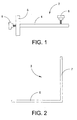
- Figure 1 shows an elevation view of the support
- Figure 2 shows a side view of the bracket
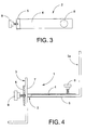
- Figure 3 shows a plan view of the support
- Figure 4 shows a support coupled to two brackets
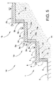
- Figure 5 shows a straight-flight stair with several connected clamps in a working position.
- the clamp (1) is seen to comprise a support (2) and a bracket (3).
- the support (2) comprises a horizontal segment (4) and a vertical segment (5) that respectively allow to displace the horizontal segment (6) of a bracket (3a) and the vertical segment (7) of the bracket (3) corresponding to the step immediately below.
- each step (11) comprises a horizontal wall (12), a vertical wall (13) and a filler with a matrix (14).
- the first step (11) is placed by attaching the first bracket (3) to the floor by a matrix or by any other means. Then the vertical wall (13) of said first step (11) is placed against the vertical wall (7) of said bracket.
- the matrix (14) is poured and the horizontal wall (12) of the first step (11) is placed.
- the first support element (2) is attached to the first bracket (3), introducing and sliding its vertical segment (7) in the vertical segment (5) of the first support element (2).
- the support element (2) will rest against the horizontal wall (12) of the first step (11).
- the vertical segment (5) meets the end of the horizontal wall (12), acting as a stop.
- a screw (9) is used to adjust the vertical wall (7) of the first bracket (3) to the vertical wall (5) of the support element (2).
- the horizontal segment (6a) of the second bracket (3a) is adjusted to the horizontal segment (4) of the support element (2) by means of a screw (8).
- the second step (11a) is set by inserting the horizontal segment (6a) of a second bracket (3a) in the horizontal segment (4) of the first support element (2). After this the vertical wall (13a) of said second step 811a) is placed and a similar process is followed as when placing the first step (11).
- This provides a staircase with a given number of steps and with the corresponding clamps suitably placed for their support, with each clamp attached to the upper adjacent clamp.
- clamps are attached to each other by pairs facilitates their instalment and ensures the correct positioning and securing of the walls of the steps.
- brackets allow adapting the support elements to the size of the steps, as the segments of these brackets may slide into the support elements and the final position can be set by the screws.
Landscapes
- Engineering & Computer Science (AREA)
- Architecture (AREA)
- Civil Engineering (AREA)
- Structural Engineering (AREA)
- Handcart (AREA)
- Steps, Ramps, And Handrails (AREA)
- Forms Removed On Construction Sites Or Auxiliary Members Thereof (AREA)
- Ladders (AREA)
- Table Devices Or Equipment (AREA)
- Cash Registers Or Receiving Machines (AREA)
Abstract
Description
Claims (2)
- Clamp for placing straight-flight stairs, characterized in that it comprises a support element and a bracket, with the support element consisting of a horizontal segment and a vertical segment which respectively allow the displacement of the horizontal wall of a bracket and the vertical wall of the bracket corresponding to the step immediately below.
- Clamp for placing straight-flight stairs, as claimed in claim 1, characterized in that it includes two screws for respectively adjusting the two segments of the bracket according to the size of the step.
Applications Claiming Priority (2)
| Application Number | Priority Date | Filing Date | Title |
|---|---|---|---|
| ES200002798U | 2000-11-17 | ||
| ES200002798U ES1047591Y (en) | 2000-11-17 | 2000-11-17 | SARGENT FOR THE PLACEMENT OF STRAIGHT STAIRCASE. |
Publications (3)
| Publication Number | Publication Date |
|---|---|
| EP1207247A2 true EP1207247A2 (en) | 2002-05-22 |
| EP1207247A3 EP1207247A3 (en) | 2003-04-02 |
| EP1207247B1 EP1207247B1 (en) | 2006-12-27 |
Family
ID=8495723
Family Applications (1)
| Application Number | Title | Priority Date | Filing Date |
|---|---|---|---|
| EP01500271A Expired - Lifetime EP1207247B1 (en) | 2000-11-17 | 2001-11-16 | Clamp for placing straight-flight stairs |
Country Status (5)
| Country | Link |
|---|---|
| EP (1) | EP1207247B1 (en) |
| AT (1) | ATE349588T1 (en) |
| DE (1) | DE60125495T2 (en) |
| ES (1) | ES1047591Y (en) |
| PT (1) | PT1207247E (en) |
Cited By (2)
| Publication number | Priority date | Publication date | Assignee | Title |
|---|---|---|---|---|
| ITPR20120043A1 (en) * | 2012-07-04 | 2014-01-05 | Longo Costruzioni S R L | METHOD FOR LAYING UP TWO PROFILES THAT IDENTIFY A CORNER BETWEEN THEM |
| IT202300008031A1 (en) * | 2023-04-24 | 2024-10-24 | Giuseppe Sambrotta | MODULAR STRUCTURE FOR COVERING A STEP SURFACE |
Families Citing this family (1)
| Publication number | Priority date | Publication date | Assignee | Title |
|---|---|---|---|---|
| CN109610822B (en) * | 2018-12-17 | 2021-07-09 | 中国十七冶集团有限公司 | Cast-in-place stair step formwork installation device and method |
Family Cites Families (2)
| Publication number | Priority date | Publication date | Assignee | Title |
|---|---|---|---|---|
| NL79121C (en) * | 1900-01-01 | |||
| DE1253441B (en) * | 1959-07-31 | 1967-11-02 | Karl Voss | Angled formwork rail for concreting stairs |
-
2000
- 2000-11-17 ES ES200002798U patent/ES1047591Y/en not_active Expired - Fee Related
-
2001
- 2001-11-16 EP EP01500271A patent/EP1207247B1/en not_active Expired - Lifetime
- 2001-11-16 AT AT01500271T patent/ATE349588T1/en not_active IP Right Cessation
- 2001-11-16 PT PT01500271T patent/PT1207247E/en unknown
- 2001-11-16 DE DE60125495T patent/DE60125495T2/en not_active Expired - Fee Related
Cited By (2)
| Publication number | Priority date | Publication date | Assignee | Title |
|---|---|---|---|---|
| ITPR20120043A1 (en) * | 2012-07-04 | 2014-01-05 | Longo Costruzioni S R L | METHOD FOR LAYING UP TWO PROFILES THAT IDENTIFY A CORNER BETWEEN THEM |
| IT202300008031A1 (en) * | 2023-04-24 | 2024-10-24 | Giuseppe Sambrotta | MODULAR STRUCTURE FOR COVERING A STEP SURFACE |
Also Published As
| Publication number | Publication date |
|---|---|
| ATE349588T1 (en) | 2007-01-15 |
| EP1207247A3 (en) | 2003-04-02 |
| DE60125495T2 (en) | 2007-10-04 |
| DE60125495D1 (en) | 2007-02-08 |
| PT1207247E (en) | 2007-03-30 |
| ES1047591Y (en) | 2001-09-01 |
| EP1207247B1 (en) | 2006-12-27 |
| ES1047591U (en) | 2001-04-16 |
Similar Documents
| Publication | Publication Date | Title |
|---|---|---|
| EP3749816B1 (en) | Formwork system | |
| US5156753A (en) | Concrete curb form device | |
| US1941404A (en) | Tile setting machine | |
| CN109025312A (en) | A kind of multi-functional floor leveling unit and construction method | |
| US11346105B2 (en) | Concrete dowel slip tube assembly | |
| US8496398B2 (en) | Rebar sleeve unit | |
| US4666333A (en) | Manhole casting positioning apparatus | |
| EP1207247B1 (en) | Clamp for placing straight-flight stairs | |
| US7775499B2 (en) | Foundation footing form and wall form support apparatus | |
| US4892439A (en) | Screed rail system | |
| CZ294093B6 (en) | Adjusting device for positioning wall elements on a building | |
| US2535956A (en) | Method of forming screw jacks with concrete bases | |
| US20060283137A1 (en) | Side-attached anchor bolt holding bracket | |
| KR100320153B1 (en) | A Constructing Method for a Public Stadium with Precast Seat Blocks | |
| US10640947B1 (en) | In-ground swimming pool form system including support members and related methods | |
| JP2725119B2 (en) | Fixing the bathtub or waterproof pan | |
| US2543939A (en) | Process for molding building slabs in position | |
| JP3761464B2 (en) | Packing material and underfloor ventilation structure construction method | |
| JP2511635Y2 (en) | Basic top end setting jig | |
| JPH0633119Y2 (en) | Floating formwork support | |
| AU735297B2 (en) | Bar chair | |
| EP1746220A1 (en) | A modular box mould support for concrete casting | |
| AU739907B2 (en) | Tile leveling device | |
| JPH0725389Y2 (en) | Formwork for manhole | |
| AU2015101948A4 (en) | Monolithic Slab |
Legal Events
| Date | Code | Title | Description |
|---|---|---|---|
| PUAI | Public reference made under article 153(3) epc to a published international application that has entered the european phase |
Free format text: ORIGINAL CODE: 0009012 |
|
| AX | Request for extension of the european patent |
Free format text: AL;LT;LV;MK;RO;SI |
|
| PUAL | Search report despatched |
Free format text: ORIGINAL CODE: 0009013 |
|
| AK | Designated contracting states |
Designated state(s): AT BE CH CY DE DK ES FI FR GB GR IE IT LI LU MC NL PT SE TR Kind code of ref document: A3 Designated state(s): AT BE CH CY DE DK ES FI FR GB GR IE IT LI LU MC NL PT SE TR |
|
| AX | Request for extension of the european patent |
Extension state: AL LT LV MK RO SI |
|
| 17P | Request for examination filed |
Effective date: 20030522 |
|
| AKX | Designation fees paid |
Designated state(s): AT BE CH CY DE DK ES FI FR GB GR IE IT LI LU MC NL PT SE TR |
|
| GRAP | Despatch of communication of intention to grant a patent |
Free format text: ORIGINAL CODE: EPIDOSNIGR1 |
|
| GRAS | Grant fee paid |
Free format text: ORIGINAL CODE: EPIDOSNIGR3 |
|
| GRAA | (expected) grant |
Free format text: ORIGINAL CODE: 0009210 |
|
| AK | Designated contracting states |
Kind code of ref document: B1 Designated state(s): AT BE CH CY DE DK ES FI FR GB GR IE IT LI LU MC NL PT SE TR |
|
| PG25 | Lapsed in a contracting state [announced via postgrant information from national office to epo] |
Ref country code: CH Free format text: LAPSE BECAUSE OF FAILURE TO SUBMIT A TRANSLATION OF THE DESCRIPTION OR TO PAY THE FEE WITHIN THE PRESCRIBED TIME-LIMIT Effective date: 20061227 Ref country code: DK Free format text: LAPSE BECAUSE OF FAILURE TO SUBMIT A TRANSLATION OF THE DESCRIPTION OR TO PAY THE FEE WITHIN THE PRESCRIBED TIME-LIMIT Effective date: 20061227 Ref country code: LI Free format text: LAPSE BECAUSE OF FAILURE TO SUBMIT A TRANSLATION OF THE DESCRIPTION OR TO PAY THE FEE WITHIN THE PRESCRIBED TIME-LIMIT Effective date: 20061227 |
|
| REG | Reference to a national code |
Ref country code: GB Ref legal event code: FG4D |
|
| REG | Reference to a national code |
Ref country code: IE Ref legal event code: FG4D |
|
| REF | Corresponds to: |
Ref document number: 60125495 Country of ref document: DE Date of ref document: 20070208 Kind code of ref document: P |
|
| REG | Reference to a national code |
Ref country code: PT Ref legal event code: SC4A Free format text: AVAILABILITY OF NATIONAL TRANSLATION Effective date: 20070301 |
|
| REG | Reference to a national code |
Ref country code: SE Ref legal event code: TRGR |
|
| PG25 | Lapsed in a contracting state [announced via postgrant information from national office to epo] |
Ref country code: ES Free format text: LAPSE BECAUSE OF FAILURE TO SUBMIT A TRANSLATION OF THE DESCRIPTION OR TO PAY THE FEE WITHIN THE PRESCRIBED TIME-LIMIT Effective date: 20070407 |
|
| REG | Reference to a national code |
Ref country code: GR Ref legal event code: EP Ref document number: 20070400984 Country of ref document: GR |
|
| REG | Reference to a national code |
Ref country code: CH Ref legal event code: PL |
|
| ET | Fr: translation filed | ||
| PGFP | Annual fee paid to national office [announced via postgrant information from national office to epo] |
Ref country code: IE Payment date: 20070910 Year of fee payment: 7 |
|
| PLBE | No opposition filed within time limit |
Free format text: ORIGINAL CODE: 0009261 |
|
| STAA | Information on the status of an ep patent application or granted ep patent |
Free format text: STATUS: NO OPPOSITION FILED WITHIN TIME LIMIT |
|
| 26N | No opposition filed |
Effective date: 20070928 |
|
| PGFP | Annual fee paid to national office [announced via postgrant information from national office to epo] |
Ref country code: BE Payment date: 20070907 Year of fee payment: 7 Ref country code: NL Payment date: 20071130 Year of fee payment: 7 |
|
| PGFP | Annual fee paid to national office [announced via postgrant information from national office to epo] |
Ref country code: AT Payment date: 20071024 Year of fee payment: 7 Ref country code: FI Payment date: 20071012 Year of fee payment: 7 |
|
| PGFP | Annual fee paid to national office [announced via postgrant information from national office to epo] |
Ref country code: SE Payment date: 20071116 Year of fee payment: 7 |
|
| PGFP | Annual fee paid to national office [announced via postgrant information from national office to epo] |
Ref country code: FR Payment date: 20070927 Year of fee payment: 7 Ref country code: GB Payment date: 20071022 Year of fee payment: 7 |
|
| PGFP | Annual fee paid to national office [announced via postgrant information from national office to epo] |
Ref country code: DE Payment date: 20080129 Year of fee payment: 7 Ref country code: GR Payment date: 20070910 Year of fee payment: 7 |
|
| PG25 | Lapsed in a contracting state [announced via postgrant information from national office to epo] |
Ref country code: MC Free format text: LAPSE BECAUSE OF NON-PAYMENT OF DUE FEES Effective date: 20071130 |
|
| PGFP | Annual fee paid to national office [announced via postgrant information from national office to epo] |
Ref country code: TR Payment date: 20071116 Year of fee payment: 7 |
|
| PGFP | Annual fee paid to national office [announced via postgrant information from national office to epo] |
Ref country code: IT Payment date: 20071127 Year of fee payment: 7 |
|
| REG | Reference to a national code |
Ref country code: PT Ref legal event code: MM4A Free format text: LAPSE DUE TO NON-PAYMENT OF FEES Effective date: 20090518 |
|
| BERE | Be: lapsed |
Owner name: PINTO DOMINGUEZ, JOSE Effective date: 20081130 |
|
| EUG | Se: european patent has lapsed | ||
| GBPC | Gb: european patent ceased through non-payment of renewal fee |
Effective date: 20081116 |
|
| PG25 | Lapsed in a contracting state [announced via postgrant information from national office to epo] |
Ref country code: NL Free format text: LAPSE BECAUSE OF NON-PAYMENT OF DUE FEES Effective date: 20090601 Ref country code: FI Free format text: LAPSE BECAUSE OF NON-PAYMENT OF DUE FEES Effective date: 20081116 |
|
| NLV4 | Nl: lapsed or anulled due to non-payment of the annual fee |
Effective date: 20090601 |
|
| PG25 | Lapsed in a contracting state [announced via postgrant information from national office to epo] |
Ref country code: IT Free format text: LAPSE BECAUSE OF NON-PAYMENT OF DUE FEES Effective date: 20081116 Ref country code: AT Free format text: LAPSE BECAUSE OF NON-PAYMENT OF DUE FEES Effective date: 20081116 Ref country code: PT Free format text: LAPSE BECAUSE OF NON-PAYMENT OF DUE FEES Effective date: 20090518 Ref country code: CY Free format text: LAPSE BECAUSE OF FAILURE TO SUBMIT A TRANSLATION OF THE DESCRIPTION OR TO PAY THE FEE WITHIN THE PRESCRIBED TIME-LIMIT Effective date: 20061227 Ref country code: LU Free format text: LAPSE BECAUSE OF NON-PAYMENT OF DUE FEES Effective date: 20071116 |
|
| REG | Reference to a national code |
Ref country code: FR Ref legal event code: ST Effective date: 20090731 |
|
| PG25 | Lapsed in a contracting state [announced via postgrant information from national office to epo] |
Ref country code: BE Free format text: LAPSE BECAUSE OF NON-PAYMENT OF DUE FEES Effective date: 20081130 |
|
| PG25 | Lapsed in a contracting state [announced via postgrant information from national office to epo] |
Ref country code: IE Free format text: LAPSE BECAUSE OF NON-PAYMENT OF DUE FEES Effective date: 20081117 Ref country code: DE Free format text: LAPSE BECAUSE OF NON-PAYMENT OF DUE FEES Effective date: 20090603 |
|
| PG25 | Lapsed in a contracting state [announced via postgrant information from national office to epo] |
Ref country code: GR Free format text: LAPSE BECAUSE OF NON-PAYMENT OF DUE FEES Effective date: 20090603 Ref country code: GB Free format text: LAPSE BECAUSE OF NON-PAYMENT OF DUE FEES Effective date: 20081116 |
|
| PGFP | Annual fee paid to national office [announced via postgrant information from national office to epo] |
Ref country code: PT Payment date: 20070910 Year of fee payment: 7 |
|
| PG25 | Lapsed in a contracting state [announced via postgrant information from national office to epo] |
Ref country code: SE Free format text: LAPSE BECAUSE OF NON-PAYMENT OF DUE FEES Effective date: 20081117 |
|
| PG25 | Lapsed in a contracting state [announced via postgrant information from national office to epo] |
Ref country code: FR Free format text: LAPSE BECAUSE OF NON-PAYMENT OF DUE FEES Effective date: 20081130 Ref country code: TR Free format text: LAPSE BECAUSE OF NON-PAYMENT OF DUE FEES Effective date: 20100928 |
|
| PG25 | Lapsed in a contracting state [announced via postgrant information from national office to epo] |
Ref country code: TR Free format text: LAPSE BECAUSE OF NON-PAYMENT OF DUE FEES Effective date: 20081116 |