EP1207108A1 - Nozzle for filling operations with two liquid and/or gas products for filler machines - Google Patents
Nozzle for filling operations with two liquid and/or gas products for filler machines Download PDFInfo
- Publication number
- EP1207108A1 EP1207108A1 EP01204303A EP01204303A EP1207108A1 EP 1207108 A1 EP1207108 A1 EP 1207108A1 EP 01204303 A EP01204303 A EP 01204303A EP 01204303 A EP01204303 A EP 01204303A EP 1207108 A1 EP1207108 A1 EP 1207108A1
- Authority
- EP
- European Patent Office
- Prior art keywords
- opening
- hollow body
- shutter element
- container
- shutter
- Prior art date
- Legal status (The legal status is an assumption and is not a legal conclusion. Google has not performed a legal analysis and makes no representation as to the accuracy of the status listed.)
- Withdrawn
Links
Images


Classifications
-
- B—PERFORMING OPERATIONS; TRANSPORTING
- B67—OPENING, CLOSING OR CLEANING BOTTLES, JARS OR SIMILAR CONTAINERS; LIQUID HANDLING
- B67C—CLEANING, FILLING WITH LIQUIDS OR SEMILIQUIDS, OR EMPTYING, OF BOTTLES, JARS, CANS, CASKS, BARRELS, OR SIMILAR CONTAINERS, NOT OTHERWISE PROVIDED FOR; FUNNELS
- B67C3/00—Bottling liquids or semiliquids; Filling jars or cans with liquids or semiliquids using bottling or like apparatus; Filling casks or barrels with liquids or semiliquids
- B67C3/02—Bottling liquids or semiliquids; Filling jars or cans with liquids or semiliquids using bottling or like apparatus
- B67C3/22—Details
- B67C3/28—Flow-control devices, e.g. using valves
-
- B—PERFORMING OPERATIONS; TRANSPORTING
- B65—CONVEYING; PACKING; STORING; HANDLING THIN OR FILAMENTARY MATERIAL
- B65B—MACHINES, APPARATUS OR DEVICES FOR, OR METHODS OF, PACKAGING ARTICLES OR MATERIALS; UNPACKING
- B65B39/00—Nozzles, funnels or guides for introducing articles or materials into containers or wrappers
- B65B39/001—Nozzles, funnels or guides for introducing articles or materials into containers or wrappers with flow cut-off means, e.g. valves
- B65B39/004—Nozzles, funnels or guides for introducing articles or materials into containers or wrappers with flow cut-off means, e.g. valves moving linearly
-
- B—PERFORMING OPERATIONS; TRANSPORTING
- B67—OPENING, CLOSING OR CLEANING BOTTLES, JARS OR SIMILAR CONTAINERS; LIQUID HANDLING
- B67C—CLEANING, FILLING WITH LIQUIDS OR SEMILIQUIDS, OR EMPTYING, OF BOTTLES, JARS, CANS, CASKS, BARRELS, OR SIMILAR CONTAINERS, NOT OTHERWISE PROVIDED FOR; FUNNELS
- B67C3/00—Bottling liquids or semiliquids; Filling jars or cans with liquids or semiliquids using bottling or like apparatus; Filling casks or barrels with liquids or semiliquids
- B67C3/02—Bottling liquids or semiliquids; Filling jars or cans with liquids or semiliquids using bottling or like apparatus
- B67C3/023—Filling multiple liquids in a container
- B67C3/026—Filling the liquids simultaneously
Definitions
- the present invention refers to a nozzle for filling operations with two liquid and/or gas products for filler machines, in particular both static and rotary filler machines.
- the plugging shutter as it moves away from the outlet, frees the passage and can allow the liquid to escape at a greater flow rate the further the pin is from the outlet.
- This arrangement of parts has the great limitation that it only allows one single product to be dispensed, for example a liquid, at any one time. In such a way if two liquids or a liquid and a gas or other need to be dispensed inside a container, one has to foresee two successive stations for the successive and separate feeding of them in the same container.
- a purpose of the present invention is that of realising a nozzle for filling operations with two liquid and/or gas products for filler machines which solves all of the technical problems outlined previously.
- Another purpose is that of simplifying down to the minimum the apparatus and the devices connected to the interception and the control of the nozzle for filling a single container with liquid and/or gas products.
- Yet another purpose is that of easing, improving and making as fast as possible the operations connected to the filling of a container with two liquid and/or gas products.
- a nozzle for filling operations with two liquid and/or gas products for filler machines is shown, indicated as a whole with 10, and is associated with a first 12 and with a second 11 system for feeding identical or different products, in the form of a liquid and/or a gas.
- the nozzle 10 either alone or acting together with many similar units can be arranged on a filler machine of the fixed or rotary swivel type.
- the feeding systems 12 and 11 are arranged with one above and one along the side of a support structure 13 for carrying the nozzle 10.
- a base opening 14 of the first feeding system 12 is aligned with a mouth 15, of the tubular type, formed in the support structure 13 and facing downwards so as to insert into a hollow body 16 or short duct which constitutes the most outer part of the nozzle 10.
- the hollow body 16 also has a tubular form and is suitable for at least partially surrounding the mouth 15 to form a seal through a gasket 17, attached to the outside of the mouth 15 and capable of sliding on the hollow body 16.
- the presence of the gasket guarantees the seal against the leaking of the liquid and/or gas, also in the case in which the machine's first feeding system 12 is pressurised.
- the hollow body 16 has a first opening or mouth 18 for the outlet or discharge of the first liquid which can receive additional systems for conveying and slowing the fluid, such as nets or other which are not shown in the figures, for example screwed or locked in another way on the hollow body 16.
- An end portion 16a which can be connected with the junction 16b which allows the size of the opening 18 to be varied, forms part of the body 16.
- a first shutter element 21 or outer shutter, for example ogive-shaped, is fixedly connected with the mouth 15 or with the support structure 13, supported by a. spoke 20 radially turned towards the inside of the mouth 15.
- a spoke 20 for example, is likely to be one of three fins arranged at 120° and supporting the first shutter element 21.
- a passage 22 which can be used for feeding a second filling product, that being a liquid and/or gas, in an axial hollow chamber 19 of the first shutter element 21 and then in the container (not shown).
- the hollow body 16 can be moved between at least one engagement position, wherein the first opening 18 is engaged and closed by the first shutter element 21, and a disengagement position wherein the first product flows from such an opening 18, of variable size, into the aforementioned container, which is not shown.
- cylindrical ends 25 of a pair of arms (only partially shown for example in figure 1) of a control fork 27 are put on pivoting means or supports, not shown.
- the control fork 27 is centrally pivoted at 28 to a downwards extension 29 of the support structure 13 and on the other side extends as a second fork end 30, which is partially shown.
- This second end 30 is bound to the other end through a pin 31 to an end eyelet 32 of an actuator group or element, wholly indicated with 33.
- the actuator element 33 is bound at its other end through a further pin 34 to the support structure 13.
- the actuator element 33 in the example, comprises a pair of pneumatic cylinders 35 and 36 whose stroke, individual or combined, allows up to three different degrees of opening of the nozzle to be realised. In such a way it is possible to realise the mass rough filling of the container, through the two cylinders 35 and 36 actuated simultaneously, and the finishing off of the filling, through cylinder 36 alone.
- such an actuator element 33 can consist of an electric group with a brushless motor, a stepper motor, a proportional pneumatic cylinder or another device. In such a way it is possible to obtain an opening of the nozzle which can be predetermined as one wishes between totally closed and completely open, instead of only the three levels which can be obtained with the two pneumatic cylinders indicated.
- a safety spring 37 which has the function of closing the nozzle when there is no compressed air, has been foreseen. In such an eventuality the spring 37 overcomes the pressure of the liquid, the weight of the devices and the friction forces, making the nozzle close.
- a screwable regulator device with a nut and counternut, indicated with 40, arranged between the two cylinders 35 and 36 capable of allowing the stroke of the cylinder 36 to be partially reduced is foreseen.
- the first shutter element 21 comprises the axial hollow chamber 19 inside of it which, at its end facing towards the first opening 18, is also equipped with a second opening 38, coaxial with the first opening 18 and of a smaller size.
- a rod 39 which foresees at its end a second shutter element 41, also ogive-shaped, capable of closing the second opening 38, can be moved in the axial hollow chamber 19.
- annular passages for the two outlet liquid and/or gas products are defined.
- the rod 39 has a smaller diameter so as not to clog up the inside of the hollow chamber 19 and to allow the second product, coming from the second product reservoir 11, to pass.
- the rod 39 extends for an upper portion 39a thereof which is arranged in a tubular body 42 in which it slides guided and sealed thanks to the presence of gaskets 43.
- the rod 39 and 39a is connected to a piston 44 arranged in a cylinder 45 which extends upwards from the body of the first shutter element so as to define a channel 46 through the inside of it and between the tubular mouth 15 and the hollow body 16 for the passage of the first product coming from the first reservoir 12.
- a spring 50 is also foreseen.
- This elastic element 50 reacting between the piston 44 and the upper inner surface of the cylinder 45, usually keeps the piston 44, the rod 39a and 39 and thus the second shutter element 41 in the closed position for the second opening 38.
- this double-feeding arrangement 47, 48 of the cylinder 45 with an inner spring 50 allows an opening of the nozzle feeding the second product which can be predetermined as one wishes between totally closed and totally open, instead of a fixed number of only two or three levels, known up to now.
- a nozzle for filling operations with two liquid and/or gas products for filler machines is realised in a single position for filling the container according to steps which are predetermined by the user.
- a nozzle according to the invention which can be defined as a double concentric valve, or rather a double concentric shutter nozzle.
- a first product, such as a liquid, contained in the reservoir 12 must first be fed in a quantity A to occupy a considerable portion of the container, for example 80%.
- the actuator element 33 is actuated starting from a completely closed position illustrated in figure 1.
- the second product arriving from the reservoir 11 and passing through the passage 22 and through the piping 22a, flows into the hollow chamber 19 of the first shutter element 21 and from there into the underlying container.
- the dispensing takes place in both cases according to the axial direction of the nozzle with a saving of space and of costs, avoiding the use of two nozzles, one for each product.
- the quantity and the filling times of both the liquid or gas products can be chosen as desired. All of these advantages can also be used not just in a fixed position, but also, in the case of rotation, in a filler of the rotary type.
- the outlet opening 18 of the first liquid is not fixed, but moves with respect to the feeding system 12 and to the container to be filled (not shown) by an amount which is greater the bigger the size of the opening which is left open by the nozzle's shutter.
- Figure 4 shows how the second shutter element 41 can have a pointed form extending from the rod 39 thanks to the fact that the first shutter element 21 has an extremely pointed form with a restricted outlet opening 38. Such an extension leads to a lower dispensing of the second product. It is possible to have a combination as desired of the diameters of the openings 18 and 38, replacing the end elements 16a, 21 and 41.
- the presence of the gaskets 17 and 43 interposed between the fixed inner mouth 15 and the mobile outer part 16 as well as between the extension of the rod 39a and the fixed tubular body 42 inside the mouth 15 is such as to guarantee the seal against the leaking of liquids and/or gases, also in the case in which the feeding systems of the machine are pressurised.
- this nozzle allows there to be, as well as a feeding of two products, also a feeding without foam due the differing liquid levels and possibly a sucking in through the opening 18, transforming the feeding system 12 into a sucking system.
- nozzle of the present invention is susceptible to numerous modifications and variants, all covered by the same invention.
- the materials used, as well as their sizes and the components, can be whatever according to the technical requirements.
Landscapes
- Engineering & Computer Science (AREA)
- Mechanical Engineering (AREA)
- Supply Of Fluid Materials To The Packaging Location (AREA)
- Filling Of Jars Or Cans And Processes For Cleaning And Sealing Jars (AREA)
- Basic Packing Technique (AREA)
- Feeding, Discharge, Calcimining, Fusing, And Gas-Generation Devices (AREA)
- Vacuum Packaging (AREA)
Abstract
A nozzle for filling operations with two liquid and/or
gas products for filler machines which can be aligned
with a mouth of a container to be filled comprising a
first fixed shutter element (21) and a first outlet
opening (18) in a moveable hollow body (16, 16a),
wherein the hollow body (16, 16a) is associated at the
top with a first feeding system (12) for a first
product to be dispensed into the container and the
hollow body (16, 16a) can be moved between at least one
engagement position, in which the first opening (18) is
closed by the first shutter element (21), and a
disengagement position, in which such a first opening
(18) is opened and the first product flows into the
container, moreover said first shutter element (21)
being at least partially hollow (19) so as to be
equipped on one side with a second outlet opening (38),
coaxial with said first opening (18) in said hollow
body (16, 16a), and on the other side with a second
feeding system (11) for a second product to dispense
into the container, wherein a second shutter element
(41) is foreseen coaxial with said first hollow shutter
element (21) which can be moved between at least one
engagement position, wherein it closes the second
outlet opening (38), and a disengagement position
wherein it opens such a second opening (38) and the
second product flows into the container, being foreseen
control elements (33, 44) which are independent both
for the movement of the hollow body (16, 16a) and of
the second shutter (41) depending upon the type of
filling of the container which is selected.
Description
- The present invention refers to a nozzle for filling operations with two liquid and/or gas products for filler machines, in particular both static and rotary filler machines.
- It is well known that in the field of machines for filling containers with liquids, of the static, rotary or swivel type, in the filler head or in each filler head, in particular in the filling nozzle, devices capable of stopping or intercepting the flow of liquid when the measuring head is not filling anything up or has finished its work, have been realised. Moreover, devices which allow the flow of liquid to be regulated during the filling of the container have been devised.
- To the best of the Applicant's knowledge, these functions are usually obtained through the provision of a plugging shutter capable of translating backwards and forwards which, inserting into the nozzle's outlet, blocks the flow of liquid.
- Moreover, the plugging shutter, as it moves away from the outlet, frees the passage and can allow the liquid to escape at a greater flow rate the further the pin is from the outlet.
- Accordingly, it can be seen how in nozzles thus realised there is a fixed outer part, in general with respect to the machine's feeding system, which has the outlet for the liquid and a plugging shutter which is mobile, through an opening, which regulates and intercepts the flow by inserting into the outlet for the liquid towards the container to be filled.
- This arrangement of parts has the great limitation that it only allows one single product to be dispensed, for example a liquid, at any one time. In such a way if two liquids or a liquid and a gas or other need to be dispensed inside a container, one has to foresee two successive stations for the successive and separate feeding of them in the same container.
- There is, therefore, a double arrangement of a pair of nozzles, each of which is only dedicated to a single product of the two to be fed inside the container.
- All this carries high installation costs for the double presence of dispensing groups and of as many control groups, as well as the need for transportation between the first and the second nozzle for supplying the two products to the container.
- Moreover, the very fitting of two nozzles in succession requires long filling times for placing the two products in the single container.
- A purpose of the present invention is that of realising a nozzle for filling operations with two liquid and/or gas products for filler machines which solves all of the technical problems outlined previously.
- Another purpose is that of simplifying down to the minimum the apparatus and the devices connected to the interception and the control of the nozzle for filling a single container with liquid and/or gas products.
- Yet another purpose is that of easing, improving and making as fast as possible the operations connected to the filling of a container with two liquid and/or gas products.
- These and other purposes according to the present invention are achieved be realising a nozzle for filling with two liquid and/or gas products for filler machines according to claim 1.
- The characteristics and the advantages of a nozzle for filling operations with two liquid and/or gas products for filler machines according to the present invention will become clearer from the following description, given as an example and not for limiting purposes, referring to the attached schematic drawings wherein:
- figure 1 is a partial section view of a nozzle for filling operations with two liquid and/or gas products for filler machines in a completely closed position,
- figure 2 is a section view which is the same as that of figure 1 with the nozzle in an intermediate opening position,
- figure 3 is a section view which is the same as that of figure 1 with the nozzle in a maximum opening position,
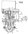
- figure 4 is a section view of the only end part of a different embodiment of the nozzle's shutter,
- With reference to the figures, a nozzle for filling operations with two liquid and/or gas products for filler machines is shown, indicated as a whole with 10, and is associated with a first 12 and with a second 11 system for feeding identical or different products, in the form of a liquid and/or a gas. The
nozzle 10 either alone or acting together with many similar units can be arranged on a filler machine of the fixed or rotary swivel type. - The
feeding systems support structure 13 for carrying thenozzle 10. A base opening 14 of thefirst feeding system 12 is aligned with amouth 15, of the tubular type, formed in thesupport structure 13 and facing downwards so as to insert into ahollow body 16 or short duct which constitutes the most outer part of thenozzle 10. - The
hollow body 16 also has a tubular form and is suitable for at least partially surrounding themouth 15 to form a seal through agasket 17, attached to the outside of themouth 15 and capable of sliding on thehollow body 16. The presence of the gasket guarantees the seal against the leaking of the liquid and/or gas, also in the case in which the machine'sfirst feeding system 12 is pressurised. - The
hollow body 16 has a first opening ormouth 18 for the outlet or discharge of the first liquid which can receive additional systems for conveying and slowing the fluid, such as nets or other which are not shown in the figures, for example screwed or locked in another way on thehollow body 16. Anend portion 16a, which can be connected with thejunction 16b which allows the size of theopening 18 to be varied, forms part of thebody 16. - A
first shutter element 21 or outer shutter, for example ogive-shaped, is fixedly connected with themouth 15 or with thesupport structure 13, supported by a. spoke 20 radially turned towards the inside of themouth 15. Such aspoke 20, for example, is likely to be one of three fins arranged at 120° and supporting thefirst shutter element 21. - In such a
spoke 20 is formed apassage 22 which can be used for feeding a second filling product, that being a liquid and/or gas, in an axialhollow chamber 19 of thefirst shutter element 21 and then in the container (not shown). - Such a
passage 22, towards the outside in the form ofpiping 22a, passes into aslot 23, formed vertically on the side surface of thehollow body 16, before being connected to a second system for feeding the second product, liquid or gas, arranged for example in the reservoir, schematised at 11. - It must, moreover, be highlighted that the
hollow body 16 can be moved between at least one engagement position, wherein thefirst opening 18 is engaged and closed by thefirst shutter element 21, and a disengagement position wherein the first product flows from such an opening 18, of variable size, into the aforementioned container, which is not shown. - For such a movement, outside of the
hollow body 16,cylindrical ends 25 of a pair of arms (only partially shown for example in figure 1) of acontrol fork 27 are put on pivoting means or supports, not shown. - The
control fork 27 is centrally pivoted at 28 to adownwards extension 29 of thesupport structure 13 and on the other side extends as asecond fork end 30, which is partially shown. Thissecond end 30 is bound to the other end through apin 31 to anend eyelet 32 of an actuator group or element, wholly indicated with 33. - The
actuator element 33 is bound at its other end through afurther pin 34 to thesupport structure 13. Theactuator element 33, in the example, comprises a pair ofpneumatic cylinders cylinders cylinder 36 alone. - In the same way, however, such an
actuator element 33 can consist of an electric group with a brushless motor, a stepper motor, a proportional pneumatic cylinder or another device. In such a way it is possible to obtain an opening of the nozzle which can be predetermined as one wishes between totally closed and completely open, instead of only the three levels which can be obtained with the two pneumatic cylinders indicated. - In the example shown with pneumatic actuators, a
safety spring 37, which has the function of closing the nozzle when there is no compressed air, has been foreseen. In such an eventuality thespring 37 overcomes the pressure of the liquid, the weight of the devices and the friction forces, making the nozzle close. On the other hand, during normal filling the force of thecylinders safety spring 37. A screwable regulator device with a nut and counternut, indicated with 40, arranged between the twocylinders cylinder 36 to be partially reduced is foreseen. - Using electric actuators the closing of the nozzle must be obtained in the case where there is no electric current: for such a purpose capacitors or batteries which supply sufficient energy to carry out the operation are used.
- According to the present invention, as already previously stated, the
first shutter element 21 comprises the axialhollow chamber 19 inside of it which, at its end facing towards the first opening 18, is also equipped with asecond opening 38, coaxial with the first opening 18 and of a smaller size. Moreover, arod 39 which foresees at its end asecond shutter element 41, also ogive-shaped, capable of closing thesecond opening 38, can be moved in the axialhollow chamber 19. In such a way, for example with both theopenings shutter elements - The
rod 39 has a smaller diameter so as not to clog up the inside of thehollow chamber 19 and to allow the second product, coming from thesecond product reservoir 11, to pass. Therod 39 extends for anupper portion 39a thereof which is arranged in atubular body 42 in which it slides guided and sealed thanks to the presence ofgaskets 43. Therod piston 44 arranged in acylinder 45 which extends upwards from the body of the first shutter element so as to define achannel 46 through the inside of it and between thetubular mouth 15 and thehollow body 16 for the passage of the first product coming from thefirst reservoir 12. - In the
cylinder 45, for example with a dual-effect and fed from a pair ofducts spring 50 is also foreseen. Thiselastic element 50, reacting between thepiston 44 and the upper inner surface of thecylinder 45, usually keeps thepiston 44, therod second shutter element 41 in the closed position for thesecond opening 38. - Also this double-
feeding arrangement cylinder 45 with aninner spring 50 allows an opening of the nozzle feeding the second product which can be predetermined as one wishes between totally closed and totally open, instead of a fixed number of only two or three levels, known up to now. - In such a way according to the present invention a nozzle for filling operations with two liquid and/or gas products for filler machines is realised in a single position for filling the container according to steps which are predetermined by the user.
- Therefore, hereafter we can give examples of some different types of filling operations which can be carried out with a nozzle according to the invention, which can be defined as a double concentric valve, or rather a double concentric shutter nozzle.
- For example a first product, such as a liquid, contained in the
reservoir 12 must first be fed in a quantity A to occupy a considerable portion of the container, for example 80%. - For such a purpose, the
actuator element 33 is actuated starting from a completely closed position illustrated in figure 1. - In such a way, in the position shown in figure 1, in which the nozzle is closed by the
shutter elements cylinders second shutter element 41 is kept in a position closing off theopening 38, whereas thehollow body 16 is moved downwards to disengage from thefirst shutter element 21 allowing a dispensing of the first liquid from the annular passage which has been created. - The abstraction of a cylinder, the one indicated with 35, allows there to be a limited passage which allows a finishing off filling of the container with the first liquid. The return of the two
cylinders - Then one must move on to the total filling of the remaining part of the container with the quantity B of 20% of the second product, such as a liquid. For such a purpose steps are taken to actuate the displacement of the
piston 44 in thecylinder 45, for example by introducing air. The air introduced by theduct 47 raises the piston, compressing thespring 50, and thus raises therod second shutter element 41 with it which frees thesecond opening 38. - The second product, arriving from the
reservoir 11 and passing through thepassage 22 and through thepiping 22a, flows into thehollow chamber 19 of thefirst shutter element 21 and from there into the underlying container. - This operation continues until the container is filled with the necessary quantity, after which by inserting air through the
duct 48, also thanks to the help of thespring 50, thesecond opening 38 is closed again by thesecond shutter element 41. Thisshutter 41 is, indeed, moved into engagement by the downward movement of thepiston 44, of the upper portion of therod 39a and of therod 39, together forming a single piece. Also in this case, by appropriately acting upon thepneumatic control circuit 49 there can be an immediate or else progressive opening. In such a case the closing can also be as one wishes, either progressive or in one of two ways quoted above. - It is clear that this is one of the many examples of use of the nozzle of the invention. Indeed, a simultaneous feeding of the two products can be realised, acting upon both of the
actuator elements - It should thus be noted how in the nozzle of the present invention the opening and the closing of the flow of the two liquids or gases is realised in the same position, i.e. in a single nozzle, as opposed to that which takes place in prior art nozzles.
- The dispensing takes place in both cases according to the axial direction of the nozzle with a saving of space and of costs, avoiding the use of two nozzles, one for each product.
- Moreover, the quantity and the filling times of both the liquid or gas products can be chosen as desired. All of these advantages can also be used not just in a fixed position, but also, in the case of rotation, in a filler of the rotary type.
- It must be specified that during the opening of the nozzle and the dispensing of the first product which arrives from the upper reservoir, the outlet opening 18 of the first liquid is not fixed, but moves with respect to the
feeding system 12 and to the container to be filled (not shown) by an amount which is greater the bigger the size of the opening which is left open by the nozzle's shutter. - Figure 4 shows how the
second shutter element 41 can have a pointed form extending from therod 39 thanks to the fact that thefirst shutter element 21 has an extremely pointed form with a restrictedoutlet opening 38. Such an extension leads to a lower dispensing of the second product. It is possible to have a combination as desired of the diameters of theopenings end elements - The presence of the
gaskets inner mouth 15 and the mobileouter part 16 as well as between the extension of therod 39a and the fixedtubular body 42 inside themouth 15 is such as to guarantee the seal against the leaking of liquids and/or gases, also in the case in which the feeding systems of the machine are pressurised. - The conception of this nozzle allows there to be, as well as a feeding of two products, also a feeding without foam due the differing liquid levels and possibly a sucking in through the
opening 18, transforming thefeeding system 12 into a sucking system. - The advantages of a nozzle according to the present invention are therefore clear.
- The nozzle of the present invention, thus conceived, is susceptible to numerous modifications and variants, all covered by the same invention.
- Moreover, in its embodiment the materials used, as well as their sizes and the components, can be whatever according to the technical requirements.
Claims (10)
- Nozzle for filling operations with two liquid and/or gas products for filler machines which can be aligned with a mouth of a container to be filled with two products, liquids and/or gases, characterised in that it comprises a first fixed shutter element (21) and a first outlet opening (18) in a hollow body (16, 16a), wherein the hollow body (16, 16a) is associated at the top with a first feeding system (12) for a first product to be dispensed into the container and the hollow body (16, 16a) can be moved between at least one engagement position, in which the first opening (18) is closed by the first shutter element (21), and a disengagement position, in which such a first opening (18) is opened and the first product flows into the container, moreover said first shutter element (21) being at least partially hollow (19) so as to be equipped on one side with a second outlet opening (38), coaxial with said first opening (18) in said hollow body (16, 16a), and on the other side with a second feeding system (11) for a second product to dispense into the container, inside and coaxial with said first hollow shutter element (21) wherein is provided a second shutter element (41) which can be moved between at least one engagement position, in which it closes the second outlet opening (38), and a disengagement position in which it opens such a second opening (38) and the second product flows into the container, being foreseen control elements (33, 44) which are independent both for the movement of the hollow body (16, 16a) and of the second shutter (41) depending upon the type of filling of the container which is selected.
- Filling nozzle according to claim 1, characterised in that said two shutter elements (21, 41) are coaxial and slide one (41) in respect to the other (21) to define said second annular opening (38) for the dispensing of said second liquid or gas.
- Filling nozzle according to claim 1, characterised in that said hollow body (16) is carried through pins from the control fork (27) centrally pivoted (at 28) to said support structure (13) and hinged (at 31) to the other end of said control elements (33).
- Filling nozzle according to claim 1 or 3, characterised in that said control elements (33) comprise a pair of pneumatic cylinders (35, 36) whose stroke, individually or combined, allows up to three different degrees of opening of said first opening (18) of said nozzle to be realised.
- Filling nozzle according to claim 4, characterised in that it foresees a screwable regulator device with a nut and counternut (40), arranged between said two cylinders (35, 36) capable of allowing the stroke of the cylinder (36) to be partially reduced.
- Filling nozzle according to claim 4, characterised in that between said two cylinders (35, 36) is interposed a safety spring (37) which in rest state determines the displacement of said hollow body (16) on said first shutter element (21).
- Filling nozzle according to claim 1 or 3, characterised in that said control elements (33) comprise an electric group with a brushless motor, stepper motor or proportional pneumatic motor such as to obtain an annular opening with a movement of said hollow body (16) with respect to said first shutter element (21) in any position which can be predetermined between completely closed and completely open.
- Filling nozzle according to claim 1, characterised in that said first shutter element (21) has a hollow chamber (19) which extends in a passage (22) and in a piping (22a) which is arranged in a slot (23) formed on the side of said hollow body (16).
- Filling nozzle according to claim 1, characterised in that said second shutter element (41) is carried by a rod (39, 39a) driven by a piston (44) of a cylinder (45), which is arranged above said first shutter element (21) in a fixed mouth (15) arranged in said hollow body (16) and can be moved at least between said two positions.
- Filling nozzle according to claim 9, characterised in that said cylinder (45) is of the dual-effect type with an elastic element (50) which usually keeps said second shutter element (41) in a position to close off said second opening (38).
Applications Claiming Priority (2)
| Application Number | Priority Date | Filing Date | Title |
|---|---|---|---|
| ITMI002482 | 2000-11-17 | ||
| IT2000MI002482A IT1320083B1 (en) | 2000-11-17 | 2000-11-17 | NOZZLE FOR FILLING TWO LIQUID AND / OR GASEOUS PRODUCTS FOR FILLING MACHINES. |
Publications (1)
| Publication Number | Publication Date |
|---|---|
| EP1207108A1 true EP1207108A1 (en) | 2002-05-22 |
Family
ID=11446122
Family Applications (1)
| Application Number | Title | Priority Date | Filing Date |
|---|---|---|---|
| EP01204303A Withdrawn EP1207108A1 (en) | 2000-11-17 | 2001-11-12 | Nozzle for filling operations with two liquid and/or gas products for filler machines |
Country Status (6)
| Country | Link |
|---|---|
| US (1) | US6546970B2 (en) |
| EP (1) | EP1207108A1 (en) |
| CN (1) | CN1358574A (en) |
| BR (1) | BR0105232A (en) |
| CA (1) | CA2363327A1 (en) |
| IT (1) | IT1320083B1 (en) |
Cited By (11)
| Publication number | Priority date | Publication date | Assignee | Title |
|---|---|---|---|---|
| EP1310454B1 (en) * | 2001-11-09 | 2005-12-28 | Sig Simonazzi S.P.A. | Valve unit for filling machines |
| WO2006091159A1 (en) * | 2005-02-23 | 2006-08-31 | Norden Machinery Ab | Filling nozzle |
| EP1731478A1 (en) * | 2005-06-08 | 2006-12-13 | AZIONARIA COSTRUZIONI MACCHINE AUTOMATICHE-A.C.M.A.-S.p.A. | Machine for filling containers with liquid or powder products |
| WO2007039074A1 (en) * | 2005-09-20 | 2007-04-12 | Weightpack S.P.A. | Machine for filling containers |
| WO2009013523A1 (en) * | 2007-07-24 | 2009-01-29 | Jens Termansen | Fluid control arrangement |
| WO2009129937A1 (en) * | 2008-04-22 | 2009-10-29 | Khs Ag | Method and filling system for filling bottles or similar containers with a liquid filling material and filling material dispensed into containers |
| WO2010017888A1 (en) * | 2008-08-12 | 2010-02-18 | Khs Ag | Method for bottling a fill material consisting of at least one first and one second component |
| DE102009037780A1 (en) * | 2009-08-18 | 2011-03-03 | Khs Gmbh | Filling element for controlled filling of e.g. bottle with juice of orange, has delivery opening provided at lower side of element, where components are controlled independent of each other and associated to product valves |
| WO2011092188A1 (en) * | 2010-01-27 | 2011-08-04 | Elopak Systems Ag | Dosing device and dosing method for liquids |
| US8020590B2 (en) | 2004-11-25 | 2011-09-20 | Tgm Tecnomachines S.R.L. | Nozzle for filling a container with at least two viscous materials |
| EP2650253A1 (en) * | 2012-04-11 | 2013-10-16 | Krones AG | Multi-component filling machine for filling containers with liquids |
Families Citing this family (7)
| Publication number | Priority date | Publication date | Assignee | Title |
|---|---|---|---|---|
| US7011117B1 (en) * | 2004-11-15 | 2006-03-14 | Gerald Albert Carpino | Filling valve |
| DE102008010078A1 (en) * | 2008-02-19 | 2009-09-17 | Khs Ag | A method for filling containers with a consisting of at least two components filling, filling and filling machine for performing the method |
| DE102009032795A1 (en) | 2009-07-10 | 2011-01-13 | Krones Ag | Filling device for filling containers |
| US9126223B2 (en) | 2013-10-31 | 2015-09-08 | Nordson Corporation | Dispensing module and method for dispensing an adhesive |
| JP6120027B2 (en) * | 2015-10-01 | 2017-04-26 | 東洋製罐株式会社 | Filling equipment |
| EP3165500A1 (en) * | 2015-11-06 | 2017-05-10 | Sidel Participations | A flow control valve for a filling machine |
| US11047504B2 (en) | 2018-06-06 | 2021-06-29 | Federal Mfg. Llc | Filling machine including two-stage actuator for filling valve |
Citations (2)
| Publication number | Priority date | Publication date | Assignee | Title |
|---|---|---|---|---|
| DE2209772A1 (en) * | 1972-03-01 | 1973-09-13 | Josef Kestermann Fa | DOSING VALVE |
| WO2000020327A1 (en) * | 1998-10-02 | 2000-04-13 | Tetra Laval Holdings & Finance, S.A. | Dual-stream filling valve |
Family Cites Families (17)
| Publication number | Priority date | Publication date | Assignee | Title |
|---|---|---|---|---|
| US2750077A (en) * | 1954-01-11 | 1956-06-12 | Joe Lowe Corp | Filling nozzle attachment |
| US3267971A (en) * | 1963-07-22 | 1966-08-23 | Seymour C Graham | Packaging apparatus and process |
| US3415294A (en) * | 1967-05-01 | 1968-12-10 | Haskon Inc | Method and apparatus for antifoam filling a container |
| IT974494B (en) * | 1972-12-06 | 1974-06-20 | Colgate Palmolive Co | APPARATUS AND PROCEDURE FOR FILLING CONTAINERS WITH DETACHABLE WALLS WITH A PLURALITY OF FLUENT MATERIALS, FOR EXAMPLE TOOTHPASTES |
| US4117955A (en) * | 1977-04-13 | 1978-10-03 | Beloit Corporation | Multi-port valved nozzle for co-injection molding |
| AT390758B (en) * | 1988-09-19 | 1990-06-25 | Engel Gmbh Maschbau | INJECTION MOLDING NOZZLE FOR AN INJECTION MOLDING MACHINE |
| JPH03272821A (en) * | 1990-02-05 | 1991-12-04 | Japan Steel Works Ltd:The | Injection head |
| IT1242592B (en) * | 1990-10-12 | 1994-05-16 | Azionaria Costruzioni Acma Spa | DOSER-DISPENSER DEVICE FOR FILLING MACHINES. |
| US5097993A (en) * | 1990-11-27 | 1992-03-24 | W.A. Lane, Inc. | Pouch packaging machine fill tube and plunger rod assembly |
| US5167896A (en) * | 1991-01-16 | 1992-12-01 | Kyowa Electric & Chemical Co., Ltd. | Method of manufacturing a front cabinet for use with a display |
| US5220946A (en) * | 1991-07-01 | 1993-06-22 | Mitsubishi Jukogyo Kabushiki Kaisha | Counterpressure type container filling apparatus |
| US5292068A (en) * | 1992-08-17 | 1994-03-08 | Nordson Corporation | One-piece, zero cavity nozzle for swirl spray of adhesive |
| DE69320663T2 (en) * | 1993-12-22 | 1999-05-12 | Commer Spa | METHOD AND DEVICE FOR INJECTION MOLDING OF OBJECTS WITH A COMPLICATED SHAPE |
| US5573048A (en) * | 1994-12-05 | 1996-11-12 | Abco Automation, Inc. | Liquid filling device and method |
| US6983227B1 (en) * | 1995-01-17 | 2006-01-03 | Intertech Ventures, Ltd. | Virtual models of complex systems |
| IT1293462B1 (en) * | 1997-07-18 | 1999-03-01 | Techpack Srl | FLUID CONTAINER VALVE FOR VISCOUS LIQUIDS. |
| DE29918785U1 (en) * | 1999-10-25 | 2000-01-13 | Ipe Engineering Gmbh | Device for cleaning a dispensing head arrangement for removing beverages under gas pressure |
-
2000
- 2000-11-17 IT IT2000MI002482A patent/IT1320083B1/en active
-
2001
- 2001-11-07 US US10/040,285 patent/US6546970B2/en not_active Expired - Fee Related
- 2001-11-12 EP EP01204303A patent/EP1207108A1/en not_active Withdrawn
- 2001-11-14 BR BR0105232-2A patent/BR0105232A/en not_active Application Discontinuation
- 2001-11-15 CA CA002363327A patent/CA2363327A1/en not_active Abandoned
- 2001-11-16 CN CN01137691A patent/CN1358574A/en active Pending
Patent Citations (2)
| Publication number | Priority date | Publication date | Assignee | Title |
|---|---|---|---|---|
| DE2209772A1 (en) * | 1972-03-01 | 1973-09-13 | Josef Kestermann Fa | DOSING VALVE |
| WO2000020327A1 (en) * | 1998-10-02 | 2000-04-13 | Tetra Laval Holdings & Finance, S.A. | Dual-stream filling valve |
Cited By (21)
| Publication number | Priority date | Publication date | Assignee | Title |
|---|---|---|---|---|
| EP1310454B1 (en) * | 2001-11-09 | 2005-12-28 | Sig Simonazzi S.P.A. | Valve unit for filling machines |
| US8020590B2 (en) | 2004-11-25 | 2011-09-20 | Tgm Tecnomachines S.R.L. | Nozzle for filling a container with at least two viscous materials |
| WO2006091159A1 (en) * | 2005-02-23 | 2006-08-31 | Norden Machinery Ab | Filling nozzle |
| EP1851112A1 (en) * | 2005-02-23 | 2007-11-07 | Norden Machinery Ab | Filling nozzle |
| JP2008531404A (en) * | 2005-02-23 | 2008-08-14 | ノーデン マシーナリー エービー | Filling nozzle |
| EP1851112A4 (en) * | 2005-02-23 | 2012-03-21 | Norden Machinery Ab | Filling nozzle |
| CN100546878C (en) * | 2005-02-23 | 2009-10-07 | 诺登机械公司 | Applying nozzle |
| EP1731478A1 (en) * | 2005-06-08 | 2006-12-13 | AZIONARIA COSTRUZIONI MACCHINE AUTOMATICHE-A.C.M.A.-S.p.A. | Machine for filling containers with liquid or powder products |
| WO2007039074A1 (en) * | 2005-09-20 | 2007-04-12 | Weightpack S.P.A. | Machine for filling containers |
| WO2009013523A1 (en) * | 2007-07-24 | 2009-01-29 | Jens Termansen | Fluid control arrangement |
| US8667981B2 (en) | 2007-07-24 | 2014-03-11 | Krones Ag | Method of manufacturing a liquid discharge head |
| WO2009129937A1 (en) * | 2008-04-22 | 2009-10-29 | Khs Ag | Method and filling system for filling bottles or similar containers with a liquid filling material and filling material dispensed into containers |
| US8590581B2 (en) | 2008-04-22 | 2013-11-26 | Khs Gmbh | Method and filling system for filling bottles or similar containers with a liquid filling material and filling material dispensed into containers |
| WO2010017888A1 (en) * | 2008-08-12 | 2010-02-18 | Khs Ag | Method for bottling a fill material consisting of at least one first and one second component |
| DE102009037780A1 (en) * | 2009-08-18 | 2011-03-03 | Khs Gmbh | Filling element for controlled filling of e.g. bottle with juice of orange, has delivery opening provided at lower side of element, where components are controlled independent of each other and associated to product valves |
| CN102791612A (en) * | 2010-01-27 | 2012-11-21 | 爱洛帕克系统股份公司 | Dosing device and dosing method for liquids |
| WO2011092188A1 (en) * | 2010-01-27 | 2011-08-04 | Elopak Systems Ag | Dosing device and dosing method for liquids |
| CN102791612B (en) * | 2010-01-27 | 2014-05-07 | 爱洛帕克系统股份公司 | Dosing device and dosing method for liquids |
| RU2541293C2 (en) * | 2010-01-27 | 2015-02-10 | Элопак Зистемс Аг | Batcher and method of batching |
| US10472218B2 (en) | 2010-01-27 | 2019-11-12 | Elopak Systems Ag | Dosing device and dosing method for liquids |
| EP2650253A1 (en) * | 2012-04-11 | 2013-10-16 | Krones AG | Multi-component filling machine for filling containers with liquids |
Also Published As
| Publication number | Publication date |
|---|---|
| CN1358574A (en) | 2002-07-17 |
| ITMI20002482A1 (en) | 2002-05-17 |
| US6546970B2 (en) | 2003-04-15 |
| BR0105232A (en) | 2002-06-25 |
| US20020108676A1 (en) | 2002-08-15 |
| CA2363327A1 (en) | 2002-05-17 |
| IT1320083B1 (en) | 2003-11-18 |
Similar Documents
| Publication | Publication Date | Title |
|---|---|---|
| US6546970B2 (en) | Nozzle for filling operations with two liquid and/or gas products for filler machines | |
| CN101443243B (en) | Two-way valve | |
| JP4762307B2 (en) | Fluid discharge nozzle | |
| JP4891350B2 (en) | Adjustable flow valve for filling machine | |
| US2606696A (en) | Dispensing device | |
| KR100886335B1 (en) | Foam forming unit | |
| US5450877A (en) | Magnetically-controlled valve | |
| CN101184557A (en) | Dispensing unit | |
| EP0850838A1 (en) | Valve with controlled-action obturator for the metered delivery of fluids in automatic machines for filling containers and the like | |
| CN103090086A (en) | Pneumatically actuated liquid dispensing valve and method | |
| CA1054109A (en) | Filling unit with air-operated spool valve system | |
| EP3359483A1 (en) | Low splash fluid shutoff valve assembly | |
| WO2009051501A1 (en) | A dispenser and a method of filling a liquid additive container | |
| EP1129949B1 (en) | Filling nozzle with interception of supply liquids for filling machines | |
| CN109279170B (en) | Device for dispensing a plurality of fluid products | |
| EP1731478A1 (en) | Machine for filling containers with liquid or powder products | |
| KR101383919B1 (en) | Cosmetics container of different kind of fluid | |
| US7299947B2 (en) | Metering device for flowable products | |
| ES423475A1 (en) | Construction of valves for bottling machines | |
| US3334668A (en) | Filler for charging containers | |
| US3685554A (en) | Metering device | |
| EP2354081B1 (en) | A device for dispensing a product in a filling machine | |
| EP0234102B1 (en) | Liquid-flow control apparatus | |
| CN2877888Y (en) | Construction of glue coating apparatus | |
| EP0155736B1 (en) | Liquid filling nozzle |
Legal Events
| Date | Code | Title | Description |
|---|---|---|---|
| PUAI | Public reference made under article 153(3) epc to a published international application that has entered the european phase |
Free format text: ORIGINAL CODE: 0009012 |
|
| AX | Request for extension of the european patent |
Free format text: AL;LT;LV;MK;RO;SI |
|
| 17P | Request for examination filed |
Effective date: 20021118 |
|
| AKX | Designation fees paid |
Designated state(s): AT BE CH CY DE DK ES FI FR GB GR IE IT LI LU MC NL PT SE TR |
|
| STAA | Information on the status of an ep patent application or granted ep patent |
Free format text: STATUS: THE APPLICATION IS DEEMED TO BE WITHDRAWN |
|
| 18D | Application deemed to be withdrawn |
Effective date: 20060411 |